EP1128495A2 - Fassung für Keilsockellampe - Google Patents
Fassung für Keilsockellampe Download PDFInfo
- Publication number
- EP1128495A2 EP1128495A2 EP01104387A EP01104387A EP1128495A2 EP 1128495 A2 EP1128495 A2 EP 1128495A2 EP 01104387 A EP01104387 A EP 01104387A EP 01104387 A EP01104387 A EP 01104387A EP 1128495 A2 EP1128495 A2 EP 1128495A2
- Authority
- EP
- European Patent Office
- Prior art keywords
- wedge
- base lamp
- lamp
- socket
- rear end
- Prior art date
- Legal status (The legal status is an assumption and is not a legal conclusion. Google has not performed a legal analysis and makes no representation as to the accuracy of the status listed.)
- Granted
Links
Images


Classifications
-
- H—ELECTRICITY
- H01—ELECTRIC ELEMENTS
- H01R—ELECTRICALLY-CONDUCTIVE CONNECTIONS; STRUCTURAL ASSOCIATIONS OF A PLURALITY OF MUTUALLY-INSULATED ELECTRICAL CONNECTING ELEMENTS; COUPLING DEVICES; CURRENT COLLECTORS
- H01R33/00—Coupling devices specially adapted for supporting apparatus and having one part acting as a holder providing support and electrical connection via a counterpart which is structurally associated with the apparatus, e.g. lamp holders; Separate parts thereof
- H01R33/05—Two-pole devices
- H01R33/06—Two-pole devices with two current-carrying pins, blades or analogous contacts, having their axes parallel to each other
- H01R33/09—Two-pole devices with two current-carrying pins, blades or analogous contacts, having their axes parallel to each other for baseless lamp bulb
-
- H—ELECTRICITY
- H01—ELECTRIC ELEMENTS
- H01K—ELECTRIC INCANDESCENT LAMPS
- H01K1/00—Details
- H01K1/42—Means forming part of the lamp for the purpose of providing electrical connection, or support for, the lamp
- H01K1/44—Means forming part of the lamp for the purpose of providing electrical connection, or support for, the lamp directly applied to, or forming part of, the vessel
-
- H—ELECTRICITY
- H01—ELECTRIC ELEMENTS
- H01K—ELECTRIC INCANDESCENT LAMPS
- H01K1/00—Details
- H01K1/42—Means forming part of the lamp for the purpose of providing electrical connection, or support for, the lamp
- H01K1/46—Means forming part of the lamp for the purpose of providing electrical connection, or support for, the lamp supported by a separate part, e.g. base, cap
Definitions
- the present invention relates to a socket structure for fitting a lamp having no base, referred to as a wedge-base lamp.
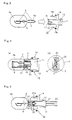
- the wedge-base lamp 1 is made of glass and is composed of a bulb portion 2a and a fixed portion 2b, as shown in FIG. 8.
- a filament 5 formed of tungsten or the like is provided in a prescribed location inside the cylindrical bulb portion 2a, and is connected to the tip end of lead wires 4.
- the lead wires 4 are fixed with a stem 6 in the bulb portion 2a, sealed by the fixed part 2b, and guided to outside from the bottom end thereof.
- the lead wires 4 guided outside are respectively folded to the surface side and the backside of the fixed portion 2b.
- a plurality of protrusions 3 are integrally provided in predetermined positions, and the wedge-base lamp does not have a base as seen in normal incandescent lamps.
- the outer diameter dimension of the fixed portion is not changed, so that a socket of a common dimension can correspond to lamps having a plurality of bulb diameters.
- FIG. 8 to FIG. 10 show a conventional connection structure of a wedge-base lamp and a socket.
- the socket 90 is to secure a wedge-base lamp 1 and to feed power thereto, and comprises an opening 90a for receiving the wedge-base lamp, an outer peripheral portion 90b and a rear end portion 90c.
- wedge-base lamp terminals 80 for feeding power to the wedge-base lamp are inserted from the opening 90a side, and terminal feet 81 are disposed on the rear end portion 90c side, through a compartment portion 90d.
- the wedge-base lamp terminal 80 comprises the terminal foot 81 and a terminal portion 82, and is formed by pressing a metal plate made of, for example, copper alloy having a thickness of 0.3mm by a die, and folding it.
- the terminal portion 82 comprises feed pawls 82a that clamp the fixed part 2b of the wedge-base lamp 1 therebetween and are brought into contact with the lead wire 4, and the tips thereof are folded inwardly three-dimensionally so as to face each other .
- the terminal foot 81 is connected to an external connection code via a connector (not shown) that is inserted from the rear end portion 90c side.
- the feed pawls 82a clamp the fixed portion 2b of the wedge-base lamp 1 from the opposite sides as well as being brought into contact with the lead wire 4 to feed power to the lamp.
- Fixation and feeding are performed by inserting and fitting the wedge-base lamp to the socket, however, terminal feet 81 (i.e., feed terminal) extending downward have to be provided for feeding, in the lower part of the socket. Accordingly, an installation space for connection with a separate connector is required, and hence the size of the rear end portion 90c should be made large. In addition, a relatively large space is required for the fixation, causing a problem in that the depth dimension becomes large.
- a wedge-base lamp fitting structure having a wedge-base lamp comprising a bulb portion, a fixed portion having no base and a lead wire at the fixed portion, a socket comprising an insertion portion for receiving and fitting the fixed portion therein, and a connector inserted and fitted into a rear end portion of the socket, wherein the socket comprises an insertion portion having a rectangular cylindrical opening with substantially the same length as that of the fixed portion in an oblong rectangular shape, and a rear end portion provided on the back side of the insertion portion, with the insertion portion and the rear end portion being provided with the continuous opening; the insertion portion having a side slit formed on the narrow side, with the opening having a plurality of pushing pieces and positioning protrusions provided therein; when the fixed portion of the wedge-base lamp is inserted into the opening in the insertion portion, the pushing pieces and positioning protrusions abut against the fixed portion of the wedge-base lamp,
- the wedge-base lamp is fixed by the socket, and secured more firmly by attaching the connector to the socket. Moreover, the feed terminal of the connector is connected to the lead wire of the wedge-base lamp. As a result, fitting becomes easier, and the depth dimension can be made smaller.
- the wedge-base lamp fitting structure according to the first aspect, wherein the insertion portion and the rear end portion are integrally formed, both using a resin material having elasticity;
- the wedge-base lamp fitting structure according to the second aspect wherein the depth of the side slit is to be substantially two thirds of the height of the fixed portion;
- the wedge-base lamp fitting structure according to any one of the first to the third aspects, wherein the pushing pieces are provided in each long side of the insertion portion, the positioning protrusions are provided in at least three prescribed locations at positions on the rear end portion side than the pushing pieces, and a protrusion quantity of the positioning protrusion into the opening is smaller than a protrusion quantity of the pushing pieces; and
- the wedge-base lamp fitting structure according to any one of the first to the fourth aspects, wherein the opening is made such that the sectional area in the rear end portion side is larger than that in the insertion portion.
- the wedge-base lamp fitting structure can be formed by integral forming, thereby enabling low cost.
- the socket secures the wedge-base lamp with an adequate spring property, to thereby make the fitting workability with the connector easier.
- the pushing pieces clamp the fixed portion from opposite sides at a position where the lead wire is provided in a prescribed location on the bulb side of the wedge-base lamp, and the fixed portion is also secured by the positioning protrusions provided on the tip side of the fixed portion, play of the fixed portion can be reduced.
- the opening on the rear end portion side is made large, thereby enabling easy execution of the connection operation with the connector.
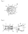
- FIG. 1 shows a construction of one embodiment of a wedge-base lamp fitting structure according to the present invention.
- reference numeral 10 denotes a socket, and the socket 10 comprises an insertion portion 12 for receiving and fitting a wedge-base lamp, a rear end portion 13 and an outer peripheral portion 14.
- the insertion portion 12 is formed in a rectangular cylindrical shape by arranging a raising wall 15 in an oblong rectangular shape in a standing condition from the outer peripheral portion 14. It is formed of a material having elasticity, such as PET (polyethylene terephthalate), PPS (polyphenylene sulfide), and PBT (polybutylene terephthalate) resin.
- a side slit 17 is formed in the narrow side of the raising wall 15, and pushing piece slits 16a, pushing pieces 16 and bottom positioning protrusions 18 are formed in the long side thereof. Since the raising wall 15 is formed of an elastic material, formation of these slits gives it a proper spring property.
- an opening 11 is provided from the insertion portion 12 up to the rear end portion 13.
- FIGs. 2, 3, 4(a) and 4(b) are illustrations for explaining the fitting structure of the wedge-base lamp 1 and the socket 10.
- the peripheral portion 14 is integrally formed with the insertion portion 12 and the rear end portion 13, and fixed to a housing of, for example, a vehicle lamp fitting.
- a fixation piece 14a having a hook structure and a sealing rubber 14b are provided, to thereby fix the peripheral portion 14 to a housing or the like (not shown).
- the rear end portion 13 is hollow inside, and an opening 11 continuous from the insertion portion 12 is formed therein.
- the opening provided in the rear end portion 13 be equal to or larger than the opening in the insertion portion 12. This is because it becomes easy to form the pushing piece 16 having a hook structure by a mold from which the molded article can be released from the rear end portion 13 side, with regard to the opening 11, as a mold for molding the socket 10 from a resin, thereby enabling reduction in the molding cost.
- the socket 10 is constructed as described above, and the wedge-base lamp is inserted and fitted into the opening 11 from the insertion portion 12 side and secured.
- wedge-base lamp 1 since it has basically the same construction as described above in the section of prior art, the same reference numerals are given to the same parts, and detailed description thereof is omitted. However, an example using a wedge-base lamp of a so-called double filament type having two filaments 5 provided therein is shown here.
- the bottom face of the fixed portion 2b abuts against the bottom positioning protrusions 18 at two positions disposed at diagonal corners inside the opening on the rear end portion side of the insertion portion 12.
- the raising wall 15 is formed in a dimension having a slightly smaller opening 11 compared to the dimension in the width direction of the insertion portion 12.
- the pushing pieces 16 formed on the raising wall 15 have pushing piece slits 16a on the opposite sides thereof, protrusions 3 in a substantially triangular shape in section formed in the fixed portion 2b of the wedge-base lamp 1 can be easily inserted into the opening 11, to thereby effect positioning and fixation by means of a hook disposed at the tip of the pushing piece 16.
- the slit size of the side slits 17 and the pushing piece slits 16a are to be an optimum size, in view of a used material, a force for inserting the wedge-base lamp, a clamping force and the like.
- the depth is at least 1/2 or more, more preferably approximately two thirds of the height of the fixed portion 2a of the wedge-base lamp, molding becomes easy and preferable.
- the slits are formed in a depth of 8mm, with the width of 0.4 to 0.8mm.
- the wedge-base lamp 1 is fixed to the socket 10 in this manner. Since the opening 11 of the socket 10 is provided continuously up to the rear end portion 13, the fixed portion 2b of the wedge-base lamp 1 can be directly observed, as shown in FIG. 4(b), seen from the rear end portion 13 in the inserted condition. Moreover, the lead wire 4 and the inner surface of the opening 11 in the rear end portion 13 are fixed so as to have a gap 20 therebetween, and a feed terminal 22 of the connector 21 is electrically connected to the lead wire 4 to thereby perform feeding.
- FIG. 5 is an illustration for explaining the construction of the fitting state of the wedge-base lamp 1 fixed in the socket 10 and the connector 21.
- the connector 21 is attached detachably by inserting the connector into the opening 11 provided in the rear end portion 13 of the socket 10.
- the shape of the tip portion 21a is substantially the same shape as that of the gap 20, and the tip portion 21a has a feed terminal 22. Therefore, insertion of the connector 21 effects direct connection of the feed terminal 22 and the lead wire 4 of the wedge-base lamp 1.
- the reference numeral 23 denotes an electric wire.
- the fitting structure of the present invention is as described above, and does not have a feed terminal in the socket. That is to say, the socket 10 performs positioning and fixation of the wedge-base lamp 1, and the connector 21 fitted into the socket performs feeding and further fixation. Therefore, an electrode terminal for the wedge base that becomes a joint for connection as in the conventional case is not required, thereby enabling reduction in the depth dimension.
- a strong fixation structure can be provided wherein further stronger fitting becomes possible by fitting the connector, compared to the fixed state at the time of fitting the wedge-base lamp into the socket, and the fitting operation can be easily performed.
- FIG. 6 and FIG. 7 are a plan view and a sectional view, respectively, showing the insertion portion side of the socket according to another embodiment of the present invention, wherein reference numeral 30 denotes a socket.
- the socket 30 of the present embodiment comprises an insertion portion 32 for fitting the wedge-base lamp, a rear end portion 33 and an outer peripheral portion 34, as in the socket 10 in the former embodiment, and an opening 31 is formed from the insertion portion 32 up to the rear end portion 33.
- the insertion portion 32 is so formed that a raising wall 35 in an oblong rectangular shape, with the insertion side (the upper side in FIG. 7) of the wedge-base lamp being enlarged, is integrally formed with an outer peripheral portion 34.
- pushing pieces 36 at two positions on the lamp insertion side and bottom positioning protrusions 38 disposed at four corners on the rear end 33 side are provided in a prescribed location of the respective long sides of the raising wall 35.
- side slits 37 are formed on the narrow sides of the raising wall 35.
- the pushing pieces 36 and the bottom positioning protrusions 38 are provided in a prescribed location alternately so as not to align linearly with respect to the lamp insertion direction, thereby enabling easy molding without performing complicated processing or the like to the mold for molding the socket.
- the peripheral portion 34 and the rear end portion 33 are formed of PET resin integrally with the insertion portion 32, and the opening 31 is to have an opening 31a of a dimension fitted with the fixed portion of the wedge-base lamp on the insertion portion 32 side, and an opening 31b having a larger sectional area than that of the opening 31a, at the rear end portion 33.
- an identification mark 39 consisting of two protrusions for identifying that the lamp to be fitted is, for example, a double-filament type wedge-base lamp.
- an unillustrated connector is inserted from the opening 31b side where the inner area on the rear end portion 33 side is made large, to thereby electrically connect the feed terminal of the connector and the lead wire in a gap between the side face of the opening 31a and the lead wire of the inserted lamp fixed portion.
- a terminal for feeding power to the socket 30 is not provided, and the socket 30 performs positioning and fixation of the wedge-base lamp, and the connector fitted into the socket performs feeding and further fixation. Therefore, an electrode terminal for the wedge base that becomes a joint for connection as in the conventional case is not required, thereby enabling reduction in the depth dimension.
- a strong fixation structure can be provided wherein further stronger fitting becomes possible by fitting the connector, compared to the fixed state at the time of fitting the wedge-base lamp into the socket, and the fitting operation can be easily performed.
- the above-described embodiments are preferable specific examples of the present invention, and various limitations technically preferable are added.
- the scope of the present invention is not limited to these aspects .
- the wedge-base lamp is fixed by the socket, and the connector is inserted and fitted into the socket from the rear end side to thereby effect direct electrical connection between the wedge-base lamp and the feed terminal disposed in the connector and further fixation, the space disposed on the rear side of the fixed portion of the wedge-base lamp can be made small, and as a result, a fitting structure having a small depth dimension can be provided.
- the wedge-base lamp is not provided with a base, and the difference in the type, such as whether the wedge-base lamp is a double-filament type or a single-filament type is determined by the difference in the protrusion shape of the fixed portion.
- the fixed portion is integrally formed of glass, there may be a case where the different point is wrongly recognized, causing a problem in that wrong fitting operation may be performed.
- an identification mark such as characters, colors or the like for recognizing the type for being fitted to the socket, enabling prevention of wrong assembly.
- the fixed portion of the wedge-base lamp one having the identical shape as the shape conventionally used can be used, thereby enabling fitting without subjecting the lamp to additional machining.
- socket 10 can also be called an adaptor.
Landscapes
- Fastening Of Light Sources Or Lamp Holders (AREA)
- Connecting Device With Holders (AREA)
Applications Claiming Priority (2)
| Application Number | Priority Date | Filing Date | Title |
|---|---|---|---|
| JP2000048491 | 2000-02-25 | ||
| JP2000048491A JP3380512B2 (ja) | 2000-02-25 | 2000-02-25 | ウエッジベース電球取付け構造 |
Publications (3)
| Publication Number | Publication Date |
|---|---|
| EP1128495A2 true EP1128495A2 (de) | 2001-08-29 |
| EP1128495A3 EP1128495A3 (de) | 2003-12-10 |
| EP1128495B1 EP1128495B1 (de) | 2006-07-19 |
Family
ID=18570571
Family Applications (1)
| Application Number | Title | Priority Date | Filing Date |
|---|---|---|---|
| EP01104387A Expired - Lifetime EP1128495B1 (de) | 2000-02-25 | 2001-02-23 | Fassung für Keilsockellampe |
Country Status (4)
| Country | Link |
|---|---|
| US (1) | US6464539B2 (de) |
| EP (1) | EP1128495B1 (de) |
| JP (1) | JP3380512B2 (de) |
| DE (1) | DE60121488T2 (de) |
Cited By (1)
| Publication number | Priority date | Publication date | Assignee | Title |
|---|---|---|---|---|
| CN103733443A (zh) * | 2011-08-10 | 2014-04-16 | 矢崎总业株式会社 | 插座 |
Families Citing this family (6)
| Publication number | Priority date | Publication date | Assignee | Title |
|---|---|---|---|---|
| US7029160B2 (en) * | 2001-04-16 | 2006-04-18 | His-Yu Huang | Lamp wedge base |
| JP4254296B2 (ja) | 2003-03-25 | 2009-04-15 | ニプロ株式会社 | 自動車用電球 |
| US7052301B2 (en) * | 2003-06-17 | 2006-05-30 | Christiana Industries, Inc. | Lamp socket |
| US6974354B2 (en) * | 2004-04-28 | 2005-12-13 | Hsin-Wei Wu | Bulb assembly |
| US7479044B1 (en) | 2007-12-07 | 2009-01-20 | St. Clair Technologies, Inc. | Lamp socket |
| US9450364B2 (en) * | 2013-12-20 | 2016-09-20 | Qtran, Inc. | Tape light electrical connector |
Family Cites Families (7)
| Publication number | Priority date | Publication date | Assignee | Title |
|---|---|---|---|---|
| DE1098623B (de) * | 1956-09-04 | 1961-02-02 | Hermann Kiefner | Fassung fuer sockellose kleine Entladungsroehren mit biegsamen Durchfuehrungsdraehten |
| DE2905872C3 (de) * | 1979-02-16 | 1981-11-19 | Rafi Gmbh & Co Elektrotechnische Spezialfabrik, 7981 Berg | Adapter zur Halterung von Leuchtdioden o.dgl. |
| US4647132A (en) * | 1984-12-17 | 1987-03-03 | Ford Motor Company | Retaining mechanism for securing a lamp base within a socket |
| US4592615A (en) * | 1985-07-03 | 1986-06-03 | Chrysler Corporation | Folded redundant terminal |
| JPH0619171A (ja) | 1992-06-30 | 1994-01-28 | Kyocera Corp | アモルファスシリコンドラムの製造方法 |
| JPH0631667A (ja) | 1992-07-21 | 1994-02-08 | Hitachi Ltd | 産業用ロボット |
| EP0708995A4 (de) * | 1993-07-13 | 1997-03-19 | Chrysler Corp | Verbindungsanordnung für lampen |
-
2000
- 2000-02-25 JP JP2000048491A patent/JP3380512B2/ja not_active Expired - Fee Related
-
2001
- 2001-02-21 US US09/788,665 patent/US6464539B2/en not_active Expired - Lifetime
- 2001-02-23 DE DE60121488T patent/DE60121488T2/de not_active Expired - Lifetime
- 2001-02-23 EP EP01104387A patent/EP1128495B1/de not_active Expired - Lifetime
Cited By (2)
| Publication number | Priority date | Publication date | Assignee | Title |
|---|---|---|---|---|
| CN103733443A (zh) * | 2011-08-10 | 2014-04-16 | 矢崎总业株式会社 | 插座 |
| US9142929B2 (en) | 2011-08-10 | 2015-09-22 | Yazaki Corporation | Socket |
Also Published As
| Publication number | Publication date |
|---|---|
| EP1128495B1 (de) | 2006-07-19 |
| DE60121488T2 (de) | 2007-02-22 |
| US6464539B2 (en) | 2002-10-15 |
| JP3380512B2 (ja) | 2003-02-24 |
| DE60121488D1 (de) | 2006-08-31 |
| US20010051462A1 (en) | 2001-12-13 |
| EP1128495A3 (de) | 2003-12-10 |
| JP2001237035A (ja) | 2001-08-31 |
Similar Documents
| Publication | Publication Date | Title |
|---|---|---|
| JPS5974687A (ja) | 発光ダイオ−ドランプ | |
| US6726496B1 (en) | Adapter for a discharge lamp | |
| EP1128495B1 (de) | Fassung für Keilsockellampe | |
| US6607293B2 (en) | Rear combination lamp | |
| US6083012A (en) | Rear combination lamp | |
| JPH11111414A (ja) | バルブソケットおよびその製造方法 | |
| JPH10208622A (ja) | コンパクト形低圧放電ランプ | |
| EP1026722B1 (de) | Leuchtstofflampe | |
| JP4221095B2 (ja) | コンパクトな低圧放電灯 | |
| JP3958399B2 (ja) | ウエッジベース電球用ソケット | |
| CN101142722A (zh) | 用于灯的灯座 | |
| US8177410B2 (en) | Lamp base and lamp | |
| JP3467355B2 (ja) | 無口金電球用ソケットおよび無口金電球装置ならびにこれを用いた照明装置 | |
| JP4216938B2 (ja) | 車両用灯具の配線部 | |
| JPH08102350A (ja) | ランプ装置および照明装置 | |
| JP3467357B2 (ja) | 無口金電球用ソケットおよび無口金電球装置ならびにこれを用いた照明装置 | |
| JPH0637591Y2 (ja) | ウエッジベース電球のソケット | |
| JPS6111904Y2 (de) | ||
| JPH064555Y2 (ja) | 無口金ランプ用ソケット装置 | |
| KR200231507Y1 (ko) | 4점 접촉부를 갖은 터미널 | |
| KR200304818Y1 (ko) | 형광등기구용 소켓 | |
| JPH0339906Y2 (de) | ||
| KR0137990Y1 (ko) | 자동차용 웨지베이스램프 소켓조립체 | |
| JP2024026670A (ja) | 光源ユニットおよび車両用灯具 | |
| JP2006147385A (ja) | 口金付電球 |
Legal Events
| Date | Code | Title | Description |
|---|---|---|---|
| PUAI | Public reference made under article 153(3) epc to a published international application that has entered the european phase |
Free format text: ORIGINAL CODE: 0009012 |
|
| AK | Designated contracting states |
Kind code of ref document: A2 Designated state(s): AT BE CH CY DE DK ES FI FR GB GR IE IT LI LU MC NL PT SE TR |
|
| AX | Request for extension of the european patent |
Free format text: AL;LT;LV;MK;RO;SI |
|
| PUAL | Search report despatched |
Free format text: ORIGINAL CODE: 0009013 |
|
| AK | Designated contracting states |
Kind code of ref document: A3 Designated state(s): AT BE CH CY DE DK ES FI FR GB GR IE IT LI LU MC NL PT SE TR |
|
| AX | Request for extension of the european patent |
Extension state: AL LT LV MK RO SI |
|
| RIC1 | Information provided on ipc code assigned before grant |
Ipc: 7H 01R 33/09 A |
|
| 17P | Request for examination filed |
Effective date: 20040601 |
|
| AKX | Designation fees paid |
Designated state(s): DE FR GB |
|
| 17Q | First examination report despatched |
Effective date: 20040812 |
|
| GRAP | Despatch of communication of intention to grant a patent |
Free format text: ORIGINAL CODE: EPIDOSNIGR1 |
|
| GRAS | Grant fee paid |
Free format text: ORIGINAL CODE: EPIDOSNIGR3 |
|
| GRAA | (expected) grant |
Free format text: ORIGINAL CODE: 0009210 |
|
| AK | Designated contracting states |
Kind code of ref document: B1 Designated state(s): DE FR GB |
|
| REG | Reference to a national code |
Ref country code: GB Ref legal event code: FG4D |
|
| REF | Corresponds to: |
Ref document number: 60121488 Country of ref document: DE Date of ref document: 20060831 Kind code of ref document: P |
|
| EN | Fr: translation not filed | ||
| PLBE | No opposition filed within time limit |
Free format text: ORIGINAL CODE: 0009261 |
|
| STAA | Information on the status of an ep patent application or granted ep patent |
Free format text: STATUS: NO OPPOSITION FILED WITHIN TIME LIMIT |
|
| 26N | No opposition filed |
Effective date: 20070420 |
|
| GBPC | Gb: european patent ceased through non-payment of renewal fee |
Effective date: 20070223 |
|
| PG25 | Lapsed in a contracting state [announced via postgrant information from national office to epo] |
Ref country code: GB Free format text: LAPSE BECAUSE OF NON-PAYMENT OF DUE FEES Effective date: 20070223 Ref country code: FR Free format text: LAPSE BECAUSE OF FAILURE TO SUBMIT A TRANSLATION OF THE DESCRIPTION OR TO PAY THE FEE WITHIN THE PRESCRIBED TIME-LIMIT Effective date: 20070511 |
|
| PG25 | Lapsed in a contracting state [announced via postgrant information from national office to epo] |
Ref country code: FR Free format text: LAPSE BECAUSE OF FAILURE TO SUBMIT A TRANSLATION OF THE DESCRIPTION OR TO PAY THE FEE WITHIN THE PRESCRIBED TIME-LIMIT Effective date: 20060719 |
|
| PGFP | Annual fee paid to national office [announced via postgrant information from national office to epo] |
Ref country code: DE Payment date: 20150218 Year of fee payment: 15 |
|
| REG | Reference to a national code |
Ref country code: DE Ref legal event code: R119 Ref document number: 60121488 Country of ref document: DE |
|
| PG25 | Lapsed in a contracting state [announced via postgrant information from national office to epo] |
Ref country code: DE Free format text: LAPSE BECAUSE OF NON-PAYMENT OF DUE FEES Effective date: 20160901 |