EP1128587A2 - Méthode et système de combinaison des signaux reçus - Google Patents
Méthode et système de combinaison des signaux reçus Download PDFInfo
- Publication number
- EP1128587A2 EP1128587A2 EP01301480A EP01301480A EP1128587A2 EP 1128587 A2 EP1128587 A2 EP 1128587A2 EP 01301480 A EP01301480 A EP 01301480A EP 01301480 A EP01301480 A EP 01301480A EP 1128587 A2 EP1128587 A2 EP 1128587A2
- Authority
- EP
- European Patent Office
- Prior art keywords
- error
- receiving station
- radio
- receiving
- signal
- Prior art date
- Legal status (The legal status is an assumption and is not a legal conclusion. Google has not performed a legal analysis and makes no representation as to the accuracy of the status listed.)
- Granted
Links
Images


Classifications
-
- H—ELECTRICITY
- H04—ELECTRIC COMMUNICATION TECHNIQUE
- H04B—TRANSMISSION
- H04B7/00—Radio transmission systems, i.e. using radiation field
- H04B7/02—Diversity systems; Multi-antenna system, i.e. transmission or reception using multiple antennas
- H04B7/022—Site diversity; Macro-diversity
-
- H—ELECTRICITY
- H04—ELECTRIC COMMUNICATION TECHNIQUE
- H04B—TRANSMISSION
- H04B7/00—Radio transmission systems, i.e. using radiation field
- H04B7/02—Diversity systems; Multi-antenna system, i.e. transmission or reception using multiple antennas
- H04B7/04—Diversity systems; Multi-antenna system, i.e. transmission or reception using multiple antennas using two or more spaced independent antennas
- H04B7/08—Diversity systems; Multi-antenna system, i.e. transmission or reception using multiple antennas using two or more spaced independent antennas at the receiving station
- H04B7/0868—Hybrid systems, i.e. switching and combining
- H04B7/0871—Hybrid systems, i.e. switching and combining using different reception schemes, at least one of them being a diversity reception scheme
-
- H—ELECTRICITY
- H04—ELECTRIC COMMUNICATION TECHNIQUE
- H04L—TRANSMISSION OF DIGITAL INFORMATION, e.g. TELEGRAPHIC COMMUNICATION
- H04L1/00—Arrangements for detecting or preventing errors in the information received
- H04L1/004—Arrangements for detecting or preventing errors in the information received by using forward error control
- H04L1/0056—Systems characterized by the type of code used
- H04L1/0064—Concatenated codes
- H04L1/0066—Parallel concatenated codes
-
- H—ELECTRICITY
- H04—ELECTRIC COMMUNICATION TECHNIQUE
- H04L—TRANSMISSION OF DIGITAL INFORMATION, e.g. TELEGRAPHIC COMMUNICATION
- H04L1/00—Arrangements for detecting or preventing errors in the information received
- H04L1/02—Arrangements for detecting or preventing errors in the information received by diversity reception
- H04L1/06—Arrangements for detecting or preventing errors in the information received by diversity reception using space diversity
Definitions
- the present invention relates to a received-signal combining method and system, and, in particular, to a received-signal combining method and system for receiving signals provided from a radio-transmitting station by a plurality of radio-receiving stations, and generating a reception signal based on the signals provided by the plurality of radio-receiving stations.
- the present invention relates to a radio-receiving station and receiving station used in such a received-signal generating method.
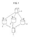
- a radio-transmitting system such as a mobile communication system rendering uplink site diversity includes, as shown in FIG. 1, a plurality of radio-receiving stations 2 (for example, base stations) are connected to a receiving station 3 (for example, control station), and, a radio-transmitting station 1 (for exmaple, a mobile set) is connected with the plurality of radio-receiving stations 2 via radio transmission paths, and renders communication therewith.
- each radio-receiving station 2 receives, from the radio-transmitting station 1, radio waves transmitted after having undergone respective processes such as error-correction coding, modulation and so forth, and, then, demodulates it and renders error-correction decoding thereon, and, then, transmits the result thereof to the receiving station 3. Then, the receiving station 3 generates a reception signal by rendering selection combining on the error-correction decoding results provided from the respective radio-receiving stations 2.
- a first object of the present invention is to provide a received-signal combing method and system by which it is possible to reduce the amount of information transmitted between each radio-receiving station (2) and receiving station (3), and, also, to obtain the reception signal having a high quality in the receiving station.
- a second object of the present invention is to provide a radio-receiving station (2) which can be used in such a received-signal combing method.
- a third object of the present invention is to provide a receiving station (3) which can be used in such a received-signal combing method.
- a received-signal combining method of transmitting signals, based on a signal having undergone error-correction coding and transmitted from a radio-transmitting station, to a receiving station from a plurality of radio-receiving stations, and generating a reception-information sequence based on the thus-transmitted signals, by the receiving station comprises the steps of:
- the error-correction-decoding results are transmitted to the receiving station from the radio-receiving stations. Then, the thus-received error-correction-decoding results are combined according to the first algorithm, and thus, the reception-information sequence is generated.
- a process rendered when an error is detected in each radio-receiving station is not particularly limited.
- a radio-receiving station at which an error is detected may transmit no signal to the receiving station.
- a standpoint of further improving the quality of the reception-information sequence obtained in the receiving station when an error is detected in each of the radio-receiving stations may transmit no signal to the receiving station.
- a received-signal combining method of transmitting signals, based on a signal having undergone error-correction coding and transmitted from a radio-transmitting station, to a receiving station from a plurality of radio-receiving stations, and generating a reception-information sequence based on the thus-transmitted signals, by the receiving station comprises the steps of:
- each radio-receiving station reports either the first information or second information to the receiving station according to the error detection result. Then, when receiving the first information from any radio-receiving station, the receiving station transmits the first signal transmitting instructions to the radio-receiving stations which transmitted the first information. When receiving the first signal transmitting instructions from the receiving station, each radio-receiving station transmits the error-correction-decoding result to the receiving station. Then, when receiving the error-correction-decoding results from the radio-receiving stations, the receiving station combines the thus-received results according to a first algorithm so as to generate the reception-information sequence,
- the receiving station When receiving the above-mentioned second information from all the radio-receiving stations, the receiving station transmits the second signal transmitting instructions to all the radio-receiving stations.
- each radio-receiving station transmits the signal before undergoing the error-correction decoding processing to the receiving station. Then, when receiving the signals before undergoing the error-correction decoding from all the radio-receiving stations, the receiving station combines the thus-received signals according to a second algorithm and then renders error-correction decoding processing so as to generate the reception-information sequence.
- the above-mentioned first and second information is not particularly limited as long as the information indicates degrees of error (degree of reliability).
- the first information indicates that no error is detected (high reliability)
- the second information indicates that an error is detected (low reliability).
- a coding algorithm in the above-mentioned systematic coding is not particularly limited, and, for exmaple, a turbo coding may be used therefor. Further, the error-correction decoding corresponds to the above-mentioned systematic coding, processing is rendered iteratively, and the error-correction-decoding result is output each time the processing is finished.
- this error-correction decoding is turbo decoding.
- each radio-receiving station when transmitting a signal obtained through the quantization of an output of a demodulator to the receiving station as the signal before undergoing the error-correction decoding processing, each radio-receiving station may produce a quantization table corresponding to two-dimensional information comprising an I-channel output signal and a Q-channel output signal of the demodulator, and render the quantization of the output of the demodulator referring to the quantization table.
- each radio-receiving station may produce a quantization table corresponding to information comprising successive I-channel output signals and Q-channel output signals of the demodulator, and render the quantization of the output of the demodulator referring to the quantization table.
- each radio-receiving station may produce a quantization table successively by using average and dispersion calculated from the output signal of the demodulator, and render the quantization of the output of the demodulator referring to the quantization table.
- each radio-receiving station may determine the number of quantization bits based on a reception SIR predicted from the signal before undergoing the error-correction decoding processing, and render quantization of the signal before undergoing the error-correction decoding processing by using the thus-determined number of quantization bits.
- each radio-receiving station may produce quantization tables different for respective ones of a system part and a redundancy part of the signal before undergoing the error-correction decoding processing, and render quantization of the system part and redundancy part of the signal before undergoing the error-correction decoding processing referring to the respective ones of the thus-produced quantization tables.
- each radio-receiving station may determine the number of quantization bits according to a state of an amount of information transmitted between the receiving station and the radio-receiving station, and render quantization of the signal before undergoing the error-correction decoding processing by using the thus-determined number of quantization bits.
- each radio-receiving station may determine the number of quantization bits according to a communication quality requested by the receiving station, and render quantization of the signal before undergoing the error-correction decoding processing by using the thus-determined number of quantization bits.
- a received-signal combining system for transmitting signals, based on a signal having undergone error-correction coding and transmitted from a radio-transmitting station, to a receiving station from a plurality of radio-receiving stations, and generating a reception-information sequence based on the thus-transmitted signals, by the receiving station,
- a received-signal combining system for transmitting signals, based on a signal having undergone error-correction coding and transmitted from a radio-transmitting station, to a receiving station from a plurality of radio-receiving stations, and generating a reception-information sequence based on the thus-transmitted signals, by the receiving station,
- the error-correction-decoding results having relatively small amounts of information are transmitted from the radio-receiving stations to the receiving station, which then combines the thus-received error-correction-decoding results, and generates the reception-information sequence. Accordingly, it is possible to obtain the reception signal having a higher quality with keeping the amount of information transmitted between each radio-receiving station and receiving station as small as possible.
- a radio-receiving station used in a received-signal combining method of transmitting signals, based on a signal having undergone error-correction coding and transmitted from a radio-transmitting station, to a receiving station from the plurality of radio-receiving stations, and generating a reception-information sequence based on the thus-transmitted signals, by the receiving station comprises:
- a radio-receiving station used in a received-signal combining method of transmitting signals, based on a signal having undergone error-correction coding and transmitted from a radio-transmitting station, to a receiving station from the plurality of radio-receiving stations, and generating a reception-information sequence based on the thus-transmitted signals, by the receiving station comprises:
- a receiving station used in a received-signal combining method of transmitting signals, based on a signal having undergone error-correction coding and transmitted from a radio-transmitting station, to the receiving station from a plurality of radio-receiving stations, and generating a reception-information sequence based on the thus-transmitted signals, by the receiving station comprises:
- a receiving station used in a received-signal combining method of transmitting signals, based on a signal having undergone error-correction coding and transmitted from a radio-transmitting station, to a receiving station from a plurality of radio-receiving stations, and generating a reception-information sequence based on the thus-transmitted signals, by the receiving station comprises:
- FIG. 2 shows a basic configuration of a radio-transmitting system in one embodiment of the present invention.
- the radio-transmitting system is achieved as a mobile communication system by which uplink site diversity can be rendered.
- a mobile set (or mobile station, corresponding to a radio-transmitting station) 10 communicates with a plurality of base stations (corresponding to radio-receiving stations) 20(1), 20(2) and 20(3) via radio-transmission paths, respectively.
- Each base stations 20(1), 20(2), 20(3) is connected to a control station (corresponding to a receiving station, and referred to as an RNC) 30 via wire.
- the RNC 30 is then connected to a network 100, and communicates with another communication unit via the network.
- the mobile set 10 has a transmitting part such as that shown in FIG. 3, for example.
- the transmitting part of the mobile set 10 includes a CRC-coding circuit 11, a turbo-coding circuit 12, a modulator 13 and a transmitter 14.
- the CRC-coding circuit 11 renders CRC coding on a transmitting information sequence which represents information to be transmitted.
- the turbo-coding circuit 12 renders turbo coding, as error-correction coding, on the information sequence having undergone the CRC coding.
- the information sequence obtained from the CRC coding and turbo coding being rendered on the transmitting information sequence is modulated by the modulator 13, and is transmitted through the transmitter 14.
- the receiving part of the base station 20(i) includes a receiver 21, a demodulator 22, a turbo-decoding circuit 23, a CRC-error-detecting circuit 24 and a switch circuit 25.
- the signal from the above-mentioned mobile set 10 is received by the receiver 21, and is demodulated by the demodulator 22.
- the turbo-decoding circuit 23 renders turbo decoding (error-correction decoding) according to an algorithm corresponding to the above-mentioned turbo coding (error-correction coding) on the demodulated output of the demodulator 22.
- the CRC-error-detecting circuit 24 renders CRC error detection on the information sequence obtained from the turbo-decoding circuit 23, according to an algorithm corresponding to the above-mentioned CRC coding.
- the output of the CRC-error-detecting circuit 24 is provided to the RNC 30 as an error detection result.
- the switch circuit 25 selects either the demodulated output from the demodulator 22 or the error-correction-decoded output from the turbo-decoding circuit 23, according to the error detection result from the CRC-error-detecting circuit 24.
- the switch circuit 25 selects the error-correction-decoded output from the turbo-decoding circuit 23.
- the switch circuit 25 selects the demodulated output from the demodulator 22. The signal thus selected by the switch circuit 25 is provided to the RNC 30.
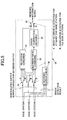
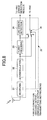
- the RNC 30 is configured as shown in FIG. 5, for exmaple.
- the RNC 30 includes a selection-combining circuit 31, a maximum-ratio-combining circuit 32, an error-correction decoding circuit 33, a first switch circuit 34, a second switch circuit 35 and an error checking circuit 36.
- the signal from each base station 20(i) is provided to either the selection-combining circuit 31 or the maximum-ratio-combining circuit 32 via the first switch circuit 34.
- the error checking circuit 36 determines whether or not a decoding error exists in each base station 20(i), based on the error detection result from the base station 20(i).
- the first switch circuit 34 includes a switching unit for each base station 20(i), and each switching unit has a port A connected to the selection-combining circuit 31 and a port B connected to the maximum-ratio-combining circuit 32.
- the switching unit corresponding to each base station 20(i) for which the error check result of the error checking circuit 36 is that 'no error exists' selects the port A, and the signal (error-correction-decoded output) from this base station 20(i) is provided to the selection-combining circuit 31.
- the switching unit corresponding to each base station 20(j) for which the error check result of the error checking circuit 36 is that 'an error exists' selects the port B, and the signal (demodulated output) from this base station (i) is provided to the maximum-ratio-combining circuit 32.
- the error-correction-decoding circuit 33 renders error-correction decoding on a combined signal output from the maximum-ratio-combining circuit 32, according to an algorithm similar to that of the above-described turbo decoding.
- the second switch circuit 35 selects, as a reception-information sequence (reception signal) either the output (port A) of the selection-combining circuit 31 or the output (port B) of the error-correction-decoding circuit 33, based on the error check result of the error checking circuit 36. Specifically, when the check result that 'no error exists' is obtained for at least one base station 20(i), the second switch circuit 35 selects, as the reception-information sequence, the output (port A) of the selection-combining circuit 31. However, when the check result that 'an error exists' for each of all the base stations, the second switch circuit 35 selects, as the reception-information sequence, the output (port B) of the error-correction-decoding circuit 33.
- a reception-information sequence thus generated by the RNC 30 is transmitted to a terminal, with which communication is made, via the network 100.
- each base station 20(1), 20(2), 20(3) is expressed as a radio-receiving station
- the RNC 30 is expressed as a receiving station (also similar in FIGS. 7A, 7B, 10A, 10B, 10C, 11A, 11B, 11C, 12, 13A, 13B, 14A, 14B and 14C).
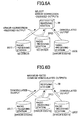
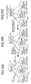
- the error-correction-decoded outputs from the turbo-decoding circuits 23 are provided to the RNC 30 from the base stations (for example, 20(1) and 20(2)) at each of which no error is detected, as shown in FIG. 6A.
- the demodulated output from the demodulator 22 is provided to the RNC 30.
- the thus-provided error-correction-decoded outputs are combined by the selection-combining circuit 31, and the thus-obtained combined signal is selected as the reception-information sequence there.
- the demodulated outputs of the demodulators 22 are provided to the RNC 30 from all of the base stations 20(1), 20(2) and 20(3), as shown in FIG. 6B.
- the demodulated outputs provided by all of the base stations 20(1), 20(2) and 20(3) are combined in a maximum-ratio combining manner by the maximum-ratio-combing circuit 22, and the thus-obtained combined signal is decoded in an error-correction decoding manner by the error-correction decoding circuit 33.
- the thus-obtained error-correction-decoded output is output from the RNC 30 as the reception-information sequence.
- the demodulated output of the demodulator 22 having a large amount of information is not needed to be transmitted to the RNC 30, but merely the error-correction-decoded output having a relatively small amount of information is needed to be transmitted to the RNC 30. Accordingly, it is possible to reduced the amount of information to be transmitted between each base station 20(1), 20(2), 20(3) which is a radio-receiving station and the RNC 30 which is a receiving station.
- the error-correction-decoded outputs from the base stations at each of which no error is detected undergo selection-combining processing in the RNC 30. Accordingly, it is possible to generate the reception-information sequence having a relatively high quality.
- the demodulate outputs signals before undergoing error-correction decoding
- the maximum-ratio-combining manner and then are decoded in the error-correction decoding manner in the RNC 30, it is possible to generate the reception-information sequence having a relatively high quality, also in this case.
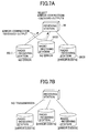
- site-diversity reception shown in FIGS. 7A and 7B can also be rendered, for example.
- the error-correction-decoded outputs of the turbo-decoding circuits 23 are provided to the RNC 30, as shown in FIG. 7A, which then renders selection combining on the thus-provided error-correction-decoded outputs.
- the base station at which the signal from the mobile set 10 is not normally received and an error is detected no signal is transmitted to the RNC 30.
- the RNC 30 when an error is detected in each of all the base stations 20(1), 20(2) and 20(3), the RNC 30 does not receive any signal from each base station, as shown in FIG. 7B. In this case, the RNC 30 treats the part of information not transmitted as a transmission error.
- each base station 20(1), 20(2), 20(3) and the RNC 30 in the radio-transmitting system such as that shown in FIG. 2 as those shown in FIGS. 8 and 9.
- the base station 20(i) includes, similar to that described above, the receiver 21, demodulator 22, turbo-decoding circuit 23 and CRC-error-detecting circuit 24. Further, the base station 20(i) includes a switch circuit 26 which performs switching operation according to a transmitting-instruction signal given from the RNC 30. When the transmitting-instruction signal for the error-correction-decoded output is input, the switch circuit 26 selects the error-correction-decoded output (port A) from the turbo-decoding circuit 23. When the transmitting-instruction signal for the demodulated output is input, the switch circuit 26 selects the demodulated output (port B) from the demodulator 22. Then, the signal thus selected by the switch circuit 26 is provided to the RNC 30 together with the error detection signal from the CRC-error-detecting circuit 24.
- the RNC 30 includes, similar to that described above, the selection-combining circuit 31, maximum-ratio-combining circuit 32, error-correction-decoding circuit 33, first switch circuit 34, second switch circuit 35 and error checking circuit 36.
- This RNC 30 further includes a first transmitting-instruction generating circuit 37 which generates the transmitting-instruction signal for the error-correction-decoded output, a second transmitting-instruction generating circuit 38 which generates the transmitting-instruction signal for the demodulated output, and a switch circuit 39.
- This switch circuit 39 selects either the transmitting-instruction signal for the error-correction-decoded output from the first transmitting-instruction generating circuit 37 (port A) or the transmitting-instruction signal for the demodulated signal (port B) based on the check result of error detection from the error checking circuit 36.
- the switch circuit 39 selects the transmitting-instruction signal for the error-correction-decoded output from the first transmitting-instruction generating circuit 37.
- the switch circuit 39 selects the transmitting-instruction signal for the demodulated signal from the second transmitting-instruction generating circuit 38.
- the transmitting-instruction signal thus selected by the switch circuit 39 is provided to the switch circuit 26 (see FIG. 8) of the base station for which error checking is rendered, as described above.
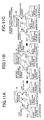
- Site-diversity reception such as that shown in FIGS. 10A, 10B, 10C, 11A, 11B and 11C is rendered in the radio-transmitting system having the base stations 20(1), 20(2) and 20(3) and RNC 30 configured as described above.
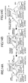
- FIGS. 10A, 10B and 10C show a case where at least one base station receives a signal from the mobile set 10 normally and no error is detected there.
- FIGS. 11A, 11B and 11C show a case where no base station can receive a signal from the mobile set 10 normally and an error is detected in each base station.
- the base stations (20(1) and 20(2)) each of which receives the signal from the mobile set 10 normally and in each of which no error is detected by the CRC-error-detecting circuit 24 transmit signals of 'high reliability' only, as the error detection result to the RNC 30 (see FIG. 10A).
- the RNC 30, having received the signals of 'high reliability' and the signal of 'low reliability', selects the above-mentioned first transmitting-instruction generating circuit 37 (see FIG. 9) and transmits the transmitting-instruction signal for the error-correction-decoded output to the base stations which have transmitted the signals of 'high reliability', but transmits no signal to the base station which has transmitted the signal of 'low reliability' (see FIG. 10B).
- each base station which has received the transmitting-instruction signal for the error-correction-decoded output selects the port A (see FIG. 8) by the switch circuit 26 based on this transmitting-instruction signal, and as a result, the error-correction-decoded output of the turbo-decoding circuit 23 is transmitted to the RNC 30 therefrom.
- the base station which transmitted the signal of 'low reliability' to the RNC 30 as the error detection result does not have any response thereto from the RNC 30, and transmits no signal to the RNC 30 (see FIG. 10C).
- the RNC 30, having received the error-correction-decoded output transmitted from each base station which obtained the error detection result of 'high reliability', renders selection combining on the thus-received error-correction-decoded outputs, and thus generates the reception-information sequence.
- each base station 20(1), 20(2), 20(3) transmits the signal of 'low reliability' only, to the RNC 30 as the error detection result (see FIG. 11A).
- the RNC 30, having received the signals of 'low reliability' from all the base stations, selects the above-mentioned second transmitting-instruction generating circuit 37 (see FIG. 9) and transmits the transmitting-instruction signal for the demodulated output to each of all the base stations (see FIG. 11B).
- the switch circuit 26 selects the port B based on the transmitting-instruction signal (see FIG. 8), and, as a result, the demodulated output of the demodulator 22 is transmitted to the RNC 30 therefrom.
- the RNC 30, having received the demodulated outputs from all the base stations at each of which the error detection result of 'low reliability' was obtained, combines these demodulated outputs in the maximum-ratio-combining manner, and, then, renders the process of error-correction-decoding on the thus-obtained signal, and, thus, generates the reception-information sequence.
- the RNC 30 transmits the transmitting instructions for the error-correction-decoded output to the base station which has transmitted that signal.
- the RNC 30 transmits the transmitting instructions for the demodulated output to all the base stations.
- each base station after transmitting the above-mentioned information indicating the error detection result to the RNC 30, transmits to the RNC 30 the error-correction-decoded output according to the transmitting instructions when receiving the transmitting instructions for the error-correction-decoded output, but transmits to the RNC 30 the demodulated output according to the transmitting instructions when receiving the transmitting instructions for the demodulated output.
- a reception SIR Signal-to-Interference Ratio
- the RNC 30 having received the reception SIR together with the error detection results, generates the reception-information sequence by rendering selection combining on the error-correction-decoded outputs from the base stations for which the reception SIR is maximum.
- the base station for which the reception SIR is maximum can receive a signal from the mobile set 10 more positively (the probability of error detection is very low). Accordingly, even if error detection occurs in the base station for which the reception SIR is low, it is possible to prevent degradation in quality of the reception-information sequence obtained in the RNC 30.
- turbo coding is used as error-correction coding in the mobile set 10 and turbo decoding is used as error-correction decoding in each base station 20(1), 20(2), 20(3) as described above
- iterative processing is rendered in the turbo decoding processing in each base station 20(1), 20(2), 20(3).
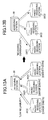
- each base station renders CRC-error detection on the error-correction-decoded output of the thus-rendered processing, and reports the error detection result of the CRC-error detection to the RNC 30. Then, in a condition in which each of all of the error detection results reported by the respective base stations is of 'low reliability' as shown in FIG.
- the RNC 30 sends instructions of 'decoding continuation' to each base station 20(1), 20(2), 20(3) as shown in FIG. 13B.
- Each base station 20(1), 20(2), 20(3) having received the instructions of 'decoding continuation' then continues the iterative processing by the turbo-decoding circuit 23.
- the RNC 30 transmits the transmitting instructions for the error-correction-decoded output to the base station (20(1)) which has transmitted the error detection result of 'high reliability', and, also, transmits decoding termination instructions to the other base stations (20(2) and 20(3)) as shown in FIG. 14B.
- the base station having received the transmitting instructions for the error-correction-decoded output transmits the error-correction-decoded output of the turbo-decoding circuit 23 to the RNC 30, as shown in FIG. 14C.
- the RNC 30 having thus received the error-correction-decoded output renders selection combining on the thus-received error-correction-decoded output, and, thus, generates the reception-information sequence.
- Each base station having received the above-mentioned decoding termination instructions terminates the iterative processing by the turbo-decoding circuit 23 whatever the result of error detection on the error-correction-decoded output at that time is.
- the mobile set 10 has a transmitting part having a convolutional-coding circuit 121 instead of the turbo-coding circuit 12. Accordingly, after CRC coding is rendered on transmitting information sequence, convolutional coding is rendered on the information sequence as error-correction coding. Then, modulation is rendered on the signal series thus obtained through the convolutional-coding circuit 121, and the thus-obtained signal is transmitted.
- each base station 20(1), 20(2), 20(3) has a receiving part having a Viterbi decoding circuit 231 configured to correspond to the above-mentioned convolutional-coding circuit 121 of the mobile set 10, instead of the turbo-decoding circuit 23. Accordingly, Viterbi decoding is rendered after reception and demodulation of a signal from the mobile set 10, and CRC error detection is rendered on the thus-obtained Viterbi-decoded output. Then, when no error is detected as a result of the CRC error detection, the Viterbi decoded output is transmitted to the RNC 30 as the error-correction-decoded output.
- each base station 20(i) has a quantization circuit 27 which quantizes the demodulated output of the demodulator 22, and runlength compressing circuit 28 which compresses the quantized output, output from the quantizing circuit 27, in a runlength-compressing manner. Accordingly, when an error is detected as a result of the CRC error detection, the demodulated output (input signal to the Viterbi decoding circuit 231) is quantized, and coded in a runlength-coding manner. Then, the thus-obtained signal is transmitted to the RNC 30.
- the above-mentioned quantization circuit 27 in each base station 20(i) can be configured as shown in FIG. 17, for example.
- the quantization circuit 27 includes a quantizer 271, a correlation detector 272, and a quantization-table producing circuit 273.
- the demodulator 22 which demodulates a received signal obtained through the receiver 21 has an I-channel and a Q-channel.
- the signals from the I-channel and Q-channel of the demodulator 22 obtained through the demodulation are input to the correlation detector 272.
- the correlation detector 272 measures a correlation between the signals of I-channel and Q-channel. Then, based on the measurement result of the correlation detector 272, the quantization-table producing circuit 273 produces a quantization table.
- the quantizer 271 quantizes the demodulated output given from the demodulator 22.
- the above-mentioned quantization circuit 27 can also be configured as shown in FIG. 18.
- the quantization circuit 27 includes the quantizer 271, correlation detector 272 and quantization-table producing circuit 273. Further, in this quantization circuit 27, the signals of the I-channel and Q-channel from the demodulator 22 are directly input to the correlation detector 272, and, also, are input to the correlation detector 272 via delay devices 274 and 275, respectively.
- the correlation detector 272 measures a correlation between the respective signals based on the signals of I-channel and Q-channel, and the signals delayed therefrom by the delay devices 274 and 275, respectively. Then, it is possible to reduce the number of quantization bits for the signals (for exmaple, the signal of the Q-channel and both delayed signals) other than a certain signal (for example, the signal of the I-channel), and, thereby, it is possible to produce the quantization table of high efficiency.
- the quantizer 271 quantizes the demodulated output from the demodulator 22.
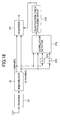
- demodulator 22 and quantization circuit 27 can be configured as shown in FIG. 19, for example. This example is applied to a radio-transmitting system in a W-CDMA (Wide-Band Code Division Multiple Access) method.
- W-CDMA Wide-Band Code Division Multiple Access
- the demodulator 22 includes a RAKE combiner 221, an average calculating part 222, a dispersion calculating part 223, a reception SIR detecting part 224 and a TPC command generating part 225.
- a dispersed received signal is reverse-dispersed, the thus-obtained signal is then combined in a RAKE combining manner, and, then, in order to generate a power control (TPC) command of the mobile set, the average and dispersion of the output signal from the RAKE combiner 221 are calculated by the average calculating part 222 and dispersion calculating part 223, respectively, successively.
- TPC power control
- the quantization-table producing circuit 273 updates a quantization table successively. Then, by referring to the thus-updated quantization table, the demodulated output (RAKE-combined output) is quantized, and, thereby, it is possible to render efficient quantization of the demodulated output.
- quantization circuit 27 can also be configured as shown in FIG. 20.
- This example is applied to a radio-transmitting system in the W-CDMA method similar to the above-mentioned exmaple.
- the demodulator 22 includes, similar to the example shown in FIG. 19, the RAKE combiner 221, average calculating part 222, dispersion calculating part 223, reception SIR detector 224 and TPC command generating part 225.
- the quantization circuit 27 includes a quantizer 271 and a quantization-bit-number determining circuit 276.
- the quantization-bit-number determining circuit 276 varies the number of quantization bits adaptively according to the reception SIR calculated for issuing the TPC command.
- the demodulated output (RAKE-combined output) is quantized by the quantizer 271.
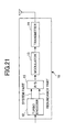
- the transmitting part of the mobile set 10 and receiving part of each base station 20(i) can also be configured as shown in FIGS. 21 and 22.
- the transmitting part of the mobile set 10 includes the turbo-coding circuit 12, a parallel-to-series converter 15, the modulator 13 and transmitter 14.
- a system part and a redundancy part of a signal coded in the turbo-coding manner output from the turbo-coding circuit 12 are multiplexed by the parallel-to-serial converter 15.
- the signal thus obtained from the multiplexing is modulated by the modulator 13, and, the thus-obtained modulated signal is transmitted from the transmitter 14.
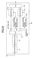
- each base station 20(i) has the demodulator 22, and, also, a series-to-parallel converter 277 which divides the signal obtained from the multiplexing performed by the transmitting part of the above-mentioned mobile set 10 into the system part and redundancy part.
- This receiving part of the base station 20(i) further includes a first quantization-table producing circuit 273a producing a quantization table for the system part of the signal, and a first quantizer 271a which quantizes the system part by referring to the quantization table produced by the first quantization-table producing circuit 273a; and a second quantization-table producing circuit 273b producing a quantization table for the redundancy part of the signal, and a second quantizer 271b which quantizes the redundancy part by referring to the quantization table produced by the second quantization-table producing circuit 273b.
- the quantized outputs of the system part and redundancy part from the first and second quantizers 271a and 271b are multiplexed by a parallel-to-series converter 278, and, thus, the reception-information sequence is generated.
- the quantization tables are produced for the system part and redundancy part of the signal individually.
- the signal of system part is more important than the signal of redundancy part. Accordingly, by producing these quantization tables such that the quantization noise is smaller for the system part of the signal than for the redundancy part of the signal, it is possible to render efficient quantization.
- each base station 20(i) can also be configured as shown in FIG. 23.
- each base station 20(i) includes the receiver 21, demodulator 22, quantizer 271 and quantization-bit-number determining circuit 276.
- the quantization-bit-number determining circuit 276 determines the number of quantization bits adaptively based on either one or both of required quality information, given from the RNC 30 which acts as a control station ranked higher than each base station 20(i), and line-capacity information between the base station and RNC 30. Then, the quantizer 172 quantizes the demodulated output by using the thus-determined number of quantization bits.
- each base station 20(i) communication having a quality required by a user, or communication having a higher quality according to a state of the amount of information transmitted between base station and RNC 30 can be rendered.
- each radio-transmitting system in each of which the mobile set 10 acts as a radio-transmitting station, the base stations 20(1), 20(2) and 20(3) act as a plurality of radio-receiving stations, and the control station RNC 30 acts as a receiving station have been described.
- the present invention is not necessary to be limited to such a configuration, and can be applied to a radio-transmitting system other than a mobile communication system.
- each radio-receiving station (base station) and receiving station (RNC) may be connected either by a wired transmission path or a radio (wireless) transmission path.
Landscapes
- Engineering & Computer Science (AREA)
- Computer Networks & Wireless Communication (AREA)
- Signal Processing (AREA)
- Detection And Prevention Of Errors In Transmission (AREA)
- Mobile Radio Communication Systems (AREA)
- Error Detection And Correction (AREA)
- Radio Transmission System (AREA)
Applications Claiming Priority (2)
| Application Number | Priority Date | Filing Date | Title |
|---|---|---|---|
| JP2000046625A JP3852736B2 (ja) | 2000-02-23 | 2000-02-23 | 受信信号合成方法、システム、無線受信局及び受信局 |
| JP2000046625 | 2000-02-23 |
Publications (3)
| Publication Number | Publication Date |
|---|---|
| EP1128587A2 true EP1128587A2 (fr) | 2001-08-29 |
| EP1128587A3 EP1128587A3 (fr) | 2003-11-26 |
| EP1128587B1 EP1128587B1 (fr) | 2008-06-11 |
Family
ID=18569005
Family Applications (1)
| Application Number | Title | Priority Date | Filing Date |
|---|---|---|---|
| EP01301480A Expired - Lifetime EP1128587B1 (fr) | 2000-02-23 | 2001-02-20 | Méthode et système de combinaison des signaux reçus |
Country Status (5)
| Country | Link |
|---|---|
| US (1) | US6915465B2 (fr) |
| EP (1) | EP1128587B1 (fr) |
| JP (1) | JP3852736B2 (fr) |
| CN (1) | CN1276669C (fr) |
| DE (1) | DE60134355D1 (fr) |
Cited By (5)
| Publication number | Priority date | Publication date | Assignee | Title |
|---|---|---|---|---|
| EP1830506A1 (fr) | 2006-03-02 | 2007-09-05 | Dibcom | Procédé de réception d'un signal sur des canaux multiples et dispositif correspondant |
| EP1936832A3 (fr) * | 2006-12-18 | 2012-03-21 | NEC Corporation | Système de communication mobile, station de base et procédé de commande pour la combinaison de signaux |
| WO2011090713A3 (fr) * | 2009-12-28 | 2013-03-14 | Qualcomm Incorporated | Réseau d'antennes virtuel pour dispositifs sans fil |
| CN109597705A (zh) * | 2018-12-05 | 2019-04-09 | 中国人民解放军国防科技大学 | 抗单粒子翻转和单粒子瞬态的高速串行接口数据编解码方法 |
| US20230208553A1 (en) * | 2020-05-26 | 2023-06-29 | Orange | Method and device for quantizing data representative of a radio signal received by a radio antenna of a mobile network |
Families Citing this family (17)
| Publication number | Priority date | Publication date | Assignee | Title |
|---|---|---|---|---|
| JP3683497B2 (ja) | 2000-11-30 | 2005-08-17 | 松下電器産業株式会社 | 復号装置および復号方法 |
| WO2003049484A1 (fr) * | 2001-11-30 | 2003-06-12 | Fujitsu Limited | Procede et appareil de commande de renvoi de donnees en paquet |
| US7287206B2 (en) * | 2002-02-13 | 2007-10-23 | Interdigital Technology Corporation | Transport block set transmission using hybrid automatic repeat request |
| JP3927082B2 (ja) * | 2002-06-13 | 2007-06-06 | 沖電気工業株式会社 | 無線データ通信における誤り訂正装置および方法 |
| JP3577307B2 (ja) * | 2002-11-26 | 2004-10-13 | 沖電気工業株式会社 | 受信装置 |
| WO2005022798A1 (fr) * | 2003-08-25 | 2005-03-10 | Interdigital Technology Corporation | Operation de liaison montante amelioree lors d'un transfert en douceur |
| US7046648B2 (en) | 2003-11-05 | 2006-05-16 | Interdigital Technology Corporation | Wireless communication method and apparatus for coordinating Node-B's and supporting enhanced uplink transmissions during handover |
| US7395079B2 (en) * | 2004-05-04 | 2008-07-01 | Telefonaktiebolaget L M Ericsson (Publ) | Methods and apparatus for selectively processing information replicas |
| FR2909241B1 (fr) * | 2006-11-27 | 2009-06-05 | Canon Kk | Procedes et dispositifs de gestion dynamique des erreurs de transmission par des points d'interconnexion de reseaux. |
| JP2009071581A (ja) * | 2007-09-13 | 2009-04-02 | Advanced Telecommunication Research Institute International | 無線装置およびそれを用いた無線ネットワーク |
| EP2202904B1 (fr) * | 2008-12-23 | 2013-10-02 | Ntt Docomo, Inc. | Station de relais et décodeur |
| EP2202894B1 (fr) | 2008-12-23 | 2011-11-02 | Ntt Docomo, Inc. | Station de relais pour système de communication mobile |
| CN102460989B (zh) * | 2009-04-28 | 2015-01-21 | 瑞典爱立信有限公司 | 协作信号通信中的量化适配技术 |
| WO2012050368A2 (fr) * | 2010-10-12 | 2012-04-19 | Samsung Electronics Co., Ltd. | Procédé et appareil pour communiquer des données de communication concernant le type de machine par l'intermédiaire d'une interface iu dans un système de communication mobile universel |
| JP6859610B2 (ja) * | 2016-05-30 | 2021-04-14 | ソニー株式会社 | 通信装置、情報処理装置、通信方法及び情報処理方法 |
| WO2019039096A1 (fr) * | 2017-08-21 | 2019-02-28 | ソニー株式会社 | Dispositif de traitement d'informations, station de base, dispositif terminal et procédé de traitement d'informations |
| JP2023086382A (ja) * | 2021-12-10 | 2023-06-22 | 株式会社東芝 | 無線統合処理装置および無線通信システム |
Family Cites Families (7)
| Publication number | Priority date | Publication date | Assignee | Title |
|---|---|---|---|---|
| US5561673A (en) * | 1993-04-16 | 1996-10-01 | Matsushita Electric Industrial Co., Ltd. | Antenna switched diversity reciever |
| US5493584A (en) * | 1993-12-27 | 1996-02-20 | Emeott; Stephen P. | Method for determining a channel quality metric in a receiver |
| US5742646A (en) * | 1995-05-05 | 1998-04-21 | Harris Corporation | Method of selecting and switching signal paths in a digital communication system |
| US5809090A (en) * | 1996-03-04 | 1998-09-15 | Glenayre Electronics, Inc. | Digital diversity receiver system |
| JP3712812B2 (ja) | 1997-03-05 | 2005-11-02 | 富士通株式会社 | 移動通信システムにおけるサイトダイバシティ受信方法、サイトダイバシティ受信方式を採用する移動通信システムにおける基地局上位装置 |
| US6272119B1 (en) * | 1997-03-26 | 2001-08-07 | Yrp Mobile Telecommunications Key Technology Research Laboratories Co., Ltd. | Method of CDMA radio wave communication with transmission quality detection and controlling and a CDMA base and mobile stations with quality detection and controlling |
| JP3094957B2 (ja) | 1997-06-30 | 2000-10-03 | 日本電気株式会社 | 移動通信システムの上り選択サイトダイバーシチにおける無線基地局受信データ伝送システム |
-
2000
- 2000-02-23 JP JP2000046625A patent/JP3852736B2/ja not_active Expired - Lifetime
-
2001
- 2001-02-20 DE DE60134355T patent/DE60134355D1/de not_active Expired - Lifetime
- 2001-02-20 EP EP01301480A patent/EP1128587B1/fr not_active Expired - Lifetime
- 2001-02-22 US US09/789,541 patent/US6915465B2/en not_active Expired - Fee Related
- 2001-02-23 CN CN01104920.0A patent/CN1276669C/zh not_active Expired - Fee Related
Cited By (9)
| Publication number | Priority date | Publication date | Assignee | Title |
|---|---|---|---|---|
| EP1830506A1 (fr) | 2006-03-02 | 2007-09-05 | Dibcom | Procédé de réception d'un signal sur des canaux multiples et dispositif correspondant |
| EP1936832A3 (fr) * | 2006-12-18 | 2012-03-21 | NEC Corporation | Système de communication mobile, station de base et procédé de commande pour la combinaison de signaux |
| US8369855B2 (en) | 2006-12-18 | 2013-02-05 | Nec Corporation | Mobile communications system and control method thereof |
| WO2011090713A3 (fr) * | 2009-12-28 | 2013-03-14 | Qualcomm Incorporated | Réseau d'antennes virtuel pour dispositifs sans fil |
| KR101434979B1 (ko) * | 2009-12-28 | 2014-08-27 | 퀄컴 인코포레이티드 | 무선 디바이스들에 대한 가상 안테나 어레이 |
| CN109597705A (zh) * | 2018-12-05 | 2019-04-09 | 中国人民解放军国防科技大学 | 抗单粒子翻转和单粒子瞬态的高速串行接口数据编解码方法 |
| CN109597705B (zh) * | 2018-12-05 | 2022-02-08 | 中国人民解放军国防科技大学 | 抗单粒子翻转和单粒子瞬态的高速串行接口数据编解码方法 |
| US20230208553A1 (en) * | 2020-05-26 | 2023-06-29 | Orange | Method and device for quantizing data representative of a radio signal received by a radio antenna of a mobile network |
| US12432010B2 (en) * | 2020-05-26 | 2025-09-30 | Orange | Method and device for quantizing data representative of a radio signal received by a radio antenna of a mobile network |
Also Published As
| Publication number | Publication date |
|---|---|
| EP1128587A3 (fr) | 2003-11-26 |
| JP2001237753A (ja) | 2001-08-31 |
| US6915465B2 (en) | 2005-07-05 |
| JP3852736B2 (ja) | 2006-12-06 |
| CN1276669C (zh) | 2006-09-20 |
| US20010020285A1 (en) | 2001-09-06 |
| DE60134355D1 (de) | 2008-07-24 |
| EP1128587B1 (fr) | 2008-06-11 |
| CN1310555A (zh) | 2001-08-29 |
Similar Documents
| Publication | Publication Date | Title |
|---|---|---|
| EP1128587B1 (fr) | Méthode et système de combinaison des signaux reçus | |
| US7769081B2 (en) | Transmission power control method for a wireless communication system | |
| KR100551001B1 (ko) | 복수의코드율을갖는셀룰러통신시스템에서송신성능을개선하기위한방법및시스템 | |
| US5729557A (en) | Cellular communication system with multiple code rates | |
| JP2877248B2 (ja) | Cdmaシステムにおける送信電力制御方法および装置 | |
| EP1172959A2 (fr) | Système et procédé hybride à demande automatique de répétition | |
| WO1997011535A9 (fr) | Systeme de communication cellulaire a debit multiple | |
| JP2009516485A (ja) | デコーディングのための方法およびシステム | |
| EP2012445A2 (fr) | Appareil et procédé de communication pour commander une réception en diversité | |
| JP2001523918A (ja) | シンボル累算を用いた時間的効率性のある再送信の方法及び装置 | |
| US20020021673A1 (en) | Method of taking account of traffic processing capacity, for traffic load control in a mobile radio network | |
| JP2004248275A (ja) | 無線送受信システム及びその方法 | |
| CN1326333C (zh) | 无线系统中的数据发送/接收装置和方法 | |
| US7289474B2 (en) | Apparatus and method for communication | |
| US20090041097A1 (en) | Apparatus and method for network-coding | |
| JP3948367B2 (ja) | 無線通信機の無線通信方法、無線通信システムの無線通信方法、無線通信システム及び無線通信機 | |
| HK1016763B (en) | Cellular communication system with multiple code rates | |
| HK1074955A (en) | Burst detector |
Legal Events
| Date | Code | Title | Description |
|---|---|---|---|
| PUAI | Public reference made under article 153(3) epc to a published international application that has entered the european phase |
Free format text: ORIGINAL CODE: 0009012 |
|
| 17P | Request for examination filed |
Effective date: 20010301 |
|
| AK | Designated contracting states |
Kind code of ref document: A2 Designated state(s): AT BE CH CY DE DK ES FI FR GB GR IE IT LI LU MC NL PT SE TR |
|
| AX | Request for extension of the european patent |
Free format text: AL;LT;LV;MK;RO;SI |
|
| PUAL | Search report despatched |
Free format text: ORIGINAL CODE: 0009013 |
|
| AK | Designated contracting states |
Kind code of ref document: A3 Designated state(s): AT BE CH CY DE DK ES FI FR GB GR IE IT LI LU MC NL PT SE TR |
|
| AX | Request for extension of the european patent |
Extension state: AL LT LV MK RO SI |
|
| AKX | Designation fees paid |
Designated state(s): DE GB |
|
| GRAP | Despatch of communication of intention to grant a patent |
Free format text: ORIGINAL CODE: EPIDOSNIGR1 |
|
| GRAS | Grant fee paid |
Free format text: ORIGINAL CODE: EPIDOSNIGR3 |
|
| GRAA | (expected) grant |
Free format text: ORIGINAL CODE: 0009210 |
|
| AK | Designated contracting states |
Kind code of ref document: B1 Designated state(s): DE GB |
|
| REG | Reference to a national code |
Ref country code: GB Ref legal event code: FG4D |
|
| REF | Corresponds to: |
Ref document number: 60134355 Country of ref document: DE Date of ref document: 20080724 Kind code of ref document: P |
|
| PLBE | No opposition filed within time limit |
Free format text: ORIGINAL CODE: 0009261 |
|
| STAA | Information on the status of an ep patent application or granted ep patent |
Free format text: STATUS: NO OPPOSITION FILED WITHIN TIME LIMIT |
|
| 26N | No opposition filed |
Effective date: 20090312 |
|
| PGFP | Annual fee paid to national office [announced via postgrant information from national office to epo] |
Ref country code: DE Payment date: 20120215 Year of fee payment: 12 |
|
| PGFP | Annual fee paid to national office [announced via postgrant information from national office to epo] |
Ref country code: GB Payment date: 20120215 Year of fee payment: 12 |
|
| GBPC | Gb: european patent ceased through non-payment of renewal fee |
Effective date: 20130220 |
|
| REG | Reference to a national code |
Ref country code: DE Ref legal event code: R119 Ref document number: 60134355 Country of ref document: DE Effective date: 20130903 |
|
| PG25 | Lapsed in a contracting state [announced via postgrant information from national office to epo] |
Ref country code: DE Free format text: LAPSE BECAUSE OF NON-PAYMENT OF DUE FEES Effective date: 20130903 Ref country code: GB Free format text: LAPSE BECAUSE OF NON-PAYMENT OF DUE FEES Effective date: 20130220 |