EP1129775A1 - Verfahren und vorrichtung zur behandlung von abgas mit fluor-verbindungen - Google Patents
Verfahren und vorrichtung zur behandlung von abgas mit fluor-verbindungen Download PDFInfo
- Publication number
- EP1129775A1 EP1129775A1 EP99936987A EP99936987A EP1129775A1 EP 1129775 A1 EP1129775 A1 EP 1129775A1 EP 99936987 A EP99936987 A EP 99936987A EP 99936987 A EP99936987 A EP 99936987A EP 1129775 A1 EP1129775 A1 EP 1129775A1
- Authority
- EP
- European Patent Office
- Prior art keywords
- fluorine
- containing compound
- gas
- exhaust gas
- aluminum oxide
- Prior art date
- Legal status (The legal status is an assumption and is not a legal conclusion. Google has not performed a legal analysis and makes no representation as to the accuracy of the status listed.)
- Ceased
Links
Images

Classifications
-
- B—PERFORMING OPERATIONS; TRANSPORTING
- B01—PHYSICAL OR CHEMICAL PROCESSES OR APPARATUS IN GENERAL
- B01D—SEPARATION
- B01D53/00—Separation of gases or vapours; Recovering vapours of volatile solvents from gases; Chemical or biological purification of waste gases, e.g. engine exhaust gases, smoke, fumes, flue gases, aerosols
- B01D53/34—Chemical or biological purification of waste gases
- B01D53/46—Removing components of defined structure
- B01D53/68—Halogens or halogen compounds
-
- B—PERFORMING OPERATIONS; TRANSPORTING
- B01—PHYSICAL OR CHEMICAL PROCESSES OR APPARATUS IN GENERAL
- B01J—CHEMICAL OR PHYSICAL PROCESSES, e.g. CATALYSIS OR COLLOID CHEMISTRY; THEIR RELEVANT APPARATUS
- B01J21/00—Catalysts comprising the elements, oxides, or hydroxides of magnesium, boron, aluminium, carbon, silicon, titanium, zirconium, or hafnium
- B01J21/02—Boron or aluminium; Oxides or hydroxides thereof
- B01J21/04—Alumina
-
- B—PERFORMING OPERATIONS; TRANSPORTING
- B01—PHYSICAL OR CHEMICAL PROCESSES OR APPARATUS IN GENERAL
- B01D—SEPARATION
- B01D53/00—Separation of gases or vapours; Recovering vapours of volatile solvents from gases; Chemical or biological purification of waste gases, e.g. engine exhaust gases, smoke, fumes, flue gases, aerosols
- B01D53/34—Chemical or biological purification of waste gases
- B01D53/74—General processes for purification of waste gases; Apparatus or devices specially adapted therefor
- B01D53/86—Catalytic processes
- B01D53/8659—Removing halogens or halogen compounds
-
- Y—GENERAL TAGGING OF NEW TECHNOLOGICAL DEVELOPMENTS; GENERAL TAGGING OF CROSS-SECTIONAL TECHNOLOGIES SPANNING OVER SEVERAL SECTIONS OF THE IPC; TECHNICAL SUBJECTS COVERED BY FORMER USPC CROSS-REFERENCE ART COLLECTIONS [XRACs] AND DIGESTS
- Y02—TECHNOLOGIES OR APPLICATIONS FOR MITIGATION OR ADAPTATION AGAINST CLIMATE CHANGE
- Y02C—CAPTURE, STORAGE, SEQUESTRATION OR DISPOSAL OF GREENHOUSE GASES [GHG]
- Y02C20/00—Capture or disposal of greenhouse gases
- Y02C20/30—Capture or disposal of greenhouse gases of perfluorocarbons [PFC], hydrofluorocarbons [HFC] or sulfur hexafluoride [SF6]
Definitions
- the present invention relates to a method and an apparatus for treating an exhaust gas containing a fluorine-containing compound. More particularly, the invention relates to a treatment method and a treatment apparatus for efficiently decomposing C 2 F 6 , C 3 F 8 , CF 4 , CHF 3 , SF 6 or NF 3 which is discharged in the step of dry cleaning the internal surface, etc. of a chamber or the like of semiconductor manufacturing equipment with the use of C 2 F 6 , C 3 F 8 , CF 4 , CHF 3 , SF 6 or NF 3 in the semiconductor industry, or during etching of various films on a semiconductor device.
- C 2 F 6 contained in an exhaust gas from a chemical vapor deposition (CVD) step and an etching step, acts as a global warming gas, and the establishment of a system for its removal is considered to be an urgent task.
- fluorinated hydrocarbons such as CF 4 , CHF 3 , and C 2 F 6
- fluorinated hydrocarbons such as CF 4 , CHF 3 , and C 2 F 6
- an exhaust gas from the etching apparatus fluorinated hydrocarbons, such as CF 4 , CHF 3 , and C 2 F 6 , are contained.
- An exhaust gas containing a fluorine-containing compound may be discharged during cleaning of a manufacturing apparatus for a semiconductor device.
- a chemical vapor deposition apparatus is used as a semiconductor device manufacturing apparatus.
- an exhaust gas including various fluorine-containing gases is discharged from the chemical vapor deposition apparatus.
- the method of catalytic thermal decomposition comprises decomposing C 2 F 6 by passing it through a heated catalyst.
- drawbacks such as a low decomposition rate, a short life of the treating agent, and occurrence of carbon monoxide (CO) as a by-product which is difficult to treat.
- the present invention aims to solve the above-described problems with the earlier technologies, and provide a method and an apparatus for treating an exhaust gas containing a fluorine-containing compound, the method and apparatus having a high decomposition rate, being effective for long periods, and involving minimal occurrence of carbon monoxide (CO).
- CO carbon monoxide
- a method for decomposing a fluorine-containing compound in an exhaust gas by contacting the exhaust gas containing the fluorine-containing compound with aluminum oxide at a high temperature enough to decompose the fluorine-containing compound.
- the above contacting step is preferably performed in the presence of a hydrogen gas (H 2 ) in a molar amount in excess of the amount required to convert the fluorine atoms in the fluorine-containing compound to HF. More preferably, the contacting step is performed in the presence of 1.5 or more times as many as the molar amount of a hydrogen gas (H 2 ) required to convert the fluorine atoms in the fluorine-containing compound to HF.
- a hydrogen gas (H 2 ) in a molar amount in excess of the amount required to convert the fluorine atoms in the fluorine-containing compound to HF.
- the contacting step is performed in the presence of an oxygen gas whose amount is not less than the number of moles of the hydrogen gas.
- the fluorine-containing compound contains a carbon atom, a sulfur atom, or a nitrogen atom
- the contacting step is performed in the presence of an oxygen gas (O 2 ) in a molar amount in excess of the amount required to convert the carbon atom to CO 2 , the sulfur atom to SO 2 , or the nitrogen atom to NO 2 .
- O 2 oxygen gas
- the aluminum oxide preferably includes ⁇ -alumina.
- the aluminum oxide is particulate.
- the high temperature is preferably in the temperature range of about 800°C to about 900°C.
- the fluorine-containing compound preferably includes C 2 F 6 , C 3 F 8 , CF 4 , CHF 3 , SF 6 or NF 3 .
- the exhaust gas preferably has been discharged from a semiconductor device manufacturing apparatus.
- the step of removing an acidic gas is present after the contacting step. Further preferably, the acidic gas is removed using water.
- an apparatus for treating an exhaust gas containing a fluorine-containing compound which includes a vessel for accommodating aluminum oxide, and a passage for passing the exhaust gas containing the fluorine-containing compound into the vessel.
- a heater capable of heating the aluminum oxide to a high temperature enough to decompose the fluorine-containing compound.
- a feeder for feeding a hydrogen gas (H 2 ) in a molar amount in excess of the amount required to convert the fluorine atoms in the fluorine-containing compound to HF.
- a feeder for feeding an oxidizing agent is further included.
- the fluorine-containing compound contains a carbon atom, a sulfur atom, or a nitrogen atom, and there is further included a feeder for feeding O 2 in a molar amount in excess of the amount required to convert the carbon atom to CO 2 , the sulfur atom to SO 2 , or the nitrogen atom to NO 2 .
- the aluminum oxide preferably includes ⁇ -alumina. More preferably, the aluminum oxide is particulate.
- the passage is preferably connected to an outlet of a semiconductor device manufacturing apparatus.
- the vessel is preferably a packed column.
- a pretreatment apparatus for removing a catalytic poison to the aluminum oxide from the exhaust gas is further present upstream from the vessel.
- a pretreatment apparatus for removing SiF 4 from the exhaust gas is further present upstream from the vessel.
- a posttreatment apparatus for removing an acidic gas is further placed downstream from the vessel.
- the posttreatment apparatus preferably removes the acidic gas by use of water.
- a method for producing a semiconductor device including the steps of:
- the contacting step is performed in the presence of a hydrogen gas (H 2 ) in a molar amount in excess of the amount required to convert the fluorine atoms in the fluorine-containing compound to HF.
- H 2 hydrogen gas
- a method for producing a semiconductor device including the steps of:
- the contacting step is performed in the presence of a hydrogen gas (H 2 ) in a molar amount in excess of the amount required to convert the fluorine atoms in the fluorine-containing compound to HF.
- H 2 hydrogen gas
- a fluorine-containing compound is decomposed at a high temperature with the use of aluminum oxide, e.g., ⁇ -alumina, as a catalyst.
- aluminum oxide e.g., ⁇ -alumina
- a perfluorocarbon such as C 2 F 6 , C 3 F 8 or CF 4
- an organic fluorine compound such as CHF 3
- an inorganic fluorine compound such as SF 6 or NF 3
- the fluorine-containing compound includes a chlorofluorocarbon such as C 2 Cl 3 F 3 , C 2 Cl 2 F 4 , or C 2 ClF 5 . Such a chlorofluorocarbon can also be decomposed.
- the fluorine-containing compound is preferably free from a chlorine atom, and is more preferably free from any of a chlorine atom, a bromine atom, and an iodine atom.
- the decomposition efficiency for the fluorine-containing compound is increased markedly by adding an H 2 gas, particularly an H 2 gas and an O 2 gas, into the exhaust gas.
- an H 2 gas By using an H 2 gas, the fluorine-containing compound can be decomposed into HF.
- a fluorine-containing compound is brought into contact with aluminum oxide in the presence of a hydrogen gas (H 2 ) in a molar amount in excess of the amount required to convert the fluorine atoms in the fluorine-containing compound to HF.
- a hydrogen gas H 2
- the hydrogen gas may be added such that the total number of the hydrogen atom in the fluorine-containing compound and the hydrogen atoms in the hydrogen gas added (H 2 ) is not less than the number of moles of the fluorine atoms in the fluorine-containing compound.
- the contacting step is performed in the presence of 1.5 or more times as many as the molar amount of a hydrogen gas (H 2 ) required to convert the fluorine atoms in the fluorine-containing compound to HF.
- decomposition is performed in the presence of O 2 in a molar amount in excess of the amount required to convert the carbon atom in the fluorine-containing compound to CO 2 , the sulfur atom in the fluorine-containing compound to SO 2 , or the nitrogen atom in the fluorine-containing compound to NO 2 . It is more preferred that decomposition is performed in the presence of O 2 in an amount of 1.5 or more times as many as this number of moles.
- the aluminum oxide ⁇ -alumina, ⁇ -alumina or ⁇ -alumina can be used, and ⁇ -alumina is preferred.
- the aluminum oxide may contain a trace amount of silicon, boron, or a transition metal such as iron, chromium, nickel, palladium, or platinum.
- the surface of the aluminum oxide may be treated with a coating.
- the shape of the aluminum oxide is not restricted, and may be particulate, powdery, or honeycomb-like. If it is particulate or powdery, a spherical particulate or powdery shape is preferred when handled.
- the particle size of the aluminum oxide is in a range in which air flow resistance does not increase when the exhaust gas is passed through the aluminum oxide. To impart a large contact area, fine particles of the aluminum oxide are satisfactory. For example, the desirable particle size is 0.8 to 2.6 mm.
- the specific surface area of the alumina is preferably 100 to 400 m 2 /g, and more preferably 120 to 300 m 2 /g.
- the temperature of the aluminum oxide may be a high temperature at which its catalytic activity is obtained.
- the temperature depends on the fluorine-containing compound, and in the case of C 2 F 6 , C 3 F 8 , CF 4 , CHF 3 , SF 6 or NF 3 , for example, the range of 800 to 900°C is preferred.
- the reaction temperature may be lower, as the number of the chlorine atoms increases.
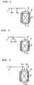
- FIGS. 1 to 3 The apparatus according to the embodiments of the present invention is shown in FIGS. 1 to 3.
- H 2 and O 2 are introduced into an exhaust gas 1 separately.
- H 2 and O 2 are introduced into an exhaust gas 1 simultaneously.
- an exhaust gas 1, H 2 and O 2 are introduced into a packed column 2 separately.
- the numeral 3 denotes ⁇ -alumina
- the numeral 4 denotes a heater.
- H 2 may be added to an exhaust gas, and then O 2 may be added to the exhaust gas.
- both H 2 and O 2 may be added to an exhaust gas.
- an exhaust gas, H 2 and O 2 may be introduced into a packed column 2 at a time, and the exhaust gas, H 2 and O 2 may be mixed inside the packed column 2.
- a feeder for feeding H 2 includes, for example, a high pressure cylinder for storing a hydrogen gas, and a regulator for controlling the pressure and flow rate of the hydrogen gas fed.
- a feeder for feeding O 2 includes, for example, a high pressure cylinder for storing an oxygen gas, and a regulator for controlling the pressure and flow rate of the hydrogen gas fed.
- a mixed gas containing an H 2 gas and an O 2 gas and an exhaust gas are introduced into the packed column 2 as downward streams. However, they may be introduced as upward streams, rather than downward streams.
- the exhaust gas after having passed through the packed column 2 contains HF.
- the exhaust gas is released to the atmosphere after removal of HF by such a measure as its passage through a water scrubber tower already installed.
- carbon monoxide (CO) is decomposed and removed, if desired, by means of an oxidation catalyst or the like.
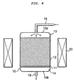
- FIG. 4 shows an embodiment of the apparatus of the present invention.
- a passage 16 for introducing an exhaust gas containing a fluorine-containing compound into a vessel 10 is connected to a top 10a of the vessel 10, and a passage 18 for discharging a treated gas from the vessel 10 is connected to a bottom 10b of the vessel 10.
- the passage 16 is connected, for example, to an outlet of a semiconductor device manufacturing apparatus.
- the vessel 10 includes a support floor 11 provided in a lower portion thereof, aluminum oxide 12 supported on the support floor 11, a first gap 13 above the aluminum oxide 12, and a second gap 14 below the aluminum oxide 12.
- the support floor 11 has many small holes of such a size as to allow the exhaust gas to pass therethrough, but does not allow the aluminum oxide 12 to pass therethrough.
- the support floor is, for example, a plate-like member composed of stainless steel.
- the gap 13 and the second gap 14 are of a sufficient size to allow the exhaust gas or mixed gas fed through the passage 16 to flow into and from the aluminum oxide 12 at a constantly desired speed.
- the exhaust gas may be introduced through the passage 18, and the treated gas may be discharged through the passage 16.
- a heater 20 capable of heating the aluminum oxide 12 is provided outside the vessel 10.
- the heater may be an electric heater, or the aluminum oxide may be heated with a heating medium, or the outside of the packed column 2 may be heated by a burner.
- the manufacturing apparatus for the semiconductor device is, for example, an etching apparatus or a chemical vapor deposition (CVD) apparatus.
- the exhaust gas generated by the manufacturing apparatus for the semiconductor device includes an exhaust gas produced in a semiconductor device manufacturing process, and an exhaust gas generated during cleaning of the manufacturing apparatus after production of the semiconductor device.
- the semiconductor device is not limited, and includes diodes, transistors, thyristors, memories such as ROM and RAM, and CPU.
- the precursor of the semiconductor device includes, for example, a substrate comprising a semiconductor, and a precursor having a thin film laminated on the substrate.
- the semiconductor of the substrate includes Group IV elements such as silicon, and compound semiconductors such as III-V compound semiconductors and II-VI compound semiconductors.
- an exhaust gas is discharged.
- the etching step in the method of manufacturing a semiconductor device is described, for example, in Japanese Patent Publication No. 14151/1981, and Japanese Patent Publication No. 45310/1982.
- the entire disclosure of Japanese Patent Publication No. 14151/1981 and Japanese Patent Publication No. 45310/1982 is incorporated herein by reference.
- semiconductor manufacturing methods and semiconductor devices are described in Jacqueline I. Kroschwitz, Mary Howe-Grant, "Kirk-Othmer Encyclopedia of Chemical Technology", Ed. 4, Vol. 21. 720-816, John Wiley & Sons, Inc., 1997. The entire description of this book is cited herein.
- the etching includes sputter etching for etching by physical impact of an etching gas, reactive ion etching for etching by the synergistic effect of physical impact of an etching gas and a chemical reaction with the etching gas, and plasma etching for etching by a chemical reaction with an etching gas without substantially involving physical impact of an etching gas.
- a fluorinated hydrocarbon such as CF 4 , CHF 3 or C 2 F 6 is used preferably as an etching gas.
- a fluorinated hydrocarbon such as CF 4 , CHF 3 or C 2 F 6 is used preferably as an etching gas.
- BCl 3 , BF 3 or Cl 2 is used preferably as an etching gas.
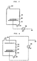
- FIG. 5 is an explanatory view of an embodiment of an etching apparatus.
- the etching apparatus has a vacuum chamber 50, and an electrode 52 placed inside the vacuum chamber 50.
- the electrode 52 is connected to a high frequency voltage 58.
- a precursor 62 of a semiconductor device for example, a semiconductor wafer is placed.
- a high frequency voltage is applied to the electrode 52, with an etching gas 64 flowing into the vacuum chamber 50, whereby sputter etching or reactive ion etching of the precursor 62 of the semiconductor device is performed.
- the type of the etching gas 64 determines whether sputter etching or reactive ion etching is performed.
- An exhaust gas 66 is discharged from the vacuum chamber, and introduced into an exhaust gas treatment apparatus.
- FIG. 5 a single electrode is used. However, a pair of electrodes 54 and 56 may be used, as shown in FIG. 6.
- a high frequency voltage 58 is applied to an electrode 54 and an electrode 56, with an etching gas 64 flowing into a vacuum chamber 50, whereby sputter etching or reactive ion etching is performed for a precursor 62 of a semiconductor device placed on the electrode 54.
- An exhaust gas 66 is discharged from the vacuum chamber, and introduced into an exhaust gas treatment apparatus.
- FIG. 7 is an explanatory view of another embodiment of the present invention.
- An exhaust gas containing a fluorine-containing compound which has been discharged from a semiconductor device manufacturing apparatus or the like, is introduced via a line 42 into a pretreatment apparatus 32 for removing a fluorine-containing inorganic compound, etc.
- the exhaust gas is introduced via a line 44 into a packed column 10 containing aluminum oxide.
- the treated gas is introduced via a line 46 into a posttreatment apparatus 34 for removing an acidic gas such as HF, and discharged through a line 48.
- As the packed column 10, that shown, for example, in FIG. 4 can be used.
- the pretreatment apparatus is, for example, a dry apparatus charged with a solid chemical such as zeolite, or a wet apparatus using a liquid chemical.
- the exhaust gas discharged from the semiconductor device manufacturing apparatus may contain tetrafluorosilicon (SiF 4 ) and an oxygen gas (O 2 ) along with tetrafluorocarbon (CF 4 ). Tetrafluorosilicon (SiF 4 ) and an oxygen gas (O 2 ) react with each other to form solid silicon oxide (SiO 2 ). That is, when the exhaust gas containing tetrafluorosilicon (SiF 4 ) and an oxygen gas (O 2 ) along with tetrafluorocarbon (CF 4 ) is contacted with aluminum oxide, solid silicon oxide (SiO 2 ) may be formed on the surface of the aluminum oxide, lowering the ability of the aluminum oxide to decompose a fluorine-containing compound.
- the exhaust gas such as SiF 4
- a catalytic poison in the exhaust gas such as SiF 4
- the exhaust gas is passed through a packed column packed with a solid chemical such as zeolite, whereby SiF 4 can be decomposed and removed.
- a fluorine-containing compound such as HF can be removed by spraying the exhaust gas with water, preferably, an alkaline liquid chemical, or by introducing the exhaust gas into water, preferably, an alkaline liquid chemical and bubbling it.
- the aluminum oxide in the packed column 10 decomposes a fluorine-containing compound, especially a fluorine-containing organic compound, into hydrogen fluoride (HF).
- HF hydrogen fluoride
- the exhaust gas discharged from the packed column 10 contains a large amount of hydrogen fluoride.
- the posttreatment apparatus for removing an acidic gas such as HF is, for example, a dry apparatus such as a packed column packed with an anion exchange resin, or a wet apparatus using water.
- the wet apparatus is, for example, a sprayer for spraying the exhaust gas with water, preferably, an alkaline liquid chemical, or a device for introducing the exhaust gas into water, preferably, an alkaline liquid chemical and bubbling it.
- a quartz column with a diameter of 25 mm was used, and packed with a treating agent to a layer height of 100 mm.
- the packed column was mounted in a ceramic electric tubular furnace, and the treating agent layer was heated to 700°C.
- a gas of C 2 F 6 alone diluted with an N 2 gas was passed through the treating agent layer.
- the flow rate of the gas was 408 sccm, and the SV was set at 500 hr -1 .
- the inlet gas concentration of C 2 F 6 was adjusted to 1%.
- the outlet gas was analyzed, where necessary.
- the removal rate of C 2 F 6 lowered to 90% or less, passage of the gas was stopped, and the amount of C 2 F 6 treated was determined based on the amount of the gas passed by then.
- the analysis of C 2 F 6 was made using a gas chromatograph equipped with a TCD detector.
- the treating agents used were all commercially available products of Mizusawa Kagaku.
- the treating agents were ⁇ -alumina (Neobead GB-26) in Reference Example 1, HY zeolite (Mizuka Sieves Y-520) in Reference Example 2, H mordenite (H Mordenite) in Reference Example 3, and H-ZSM-5 zeolite (Mizuka Sieves EX-122-H) in Reference Example 4.
- the ⁇ -alumina of Reference Example 1 was higher in performance than the H zeolites of Reference Examples 2 to 4.
- Example 1 The same testing equipment as in the preceding Reference Examples was used, and the column was packed with only ⁇ -alumina as the treating agent. The amount packed and the particle diameter were the same, and O 2 and H 2 as gases added were mixed, in arbitrary proportions, with C 2 F 6 diluted with an N 2 gas.
- the amount of H 2 added was set such that the H atomic weight was at an equal atomic ratio to the fluorine atomic weight of C 2 F 6 , and the amount of O 2 added was not less than equimolar relative to H 2 introduced.
- Comparative Examples 1 and 2 the gases added were O 2 alone and H 2 alone, respectively. In Comparative Example 3, O 2 and H 2 were both added, but the amount of H 2 was in excess of O 2 .
- the treating temperature was 800°C in all of the Examples.
- the analysis of C 2 F 6 , O 2 , H 2 , CO and CO 2 in the inlet gas and the outlet gas was quantitatively made by using a gas chromatograph equipped with a TCD detector. To investigate the treating performance, the outlet gas was analyzed, where necessary. When the removal rate of C 2 F 6 lowered to 95% or less, passage of the gas was stopped, and the amount of C 2 F 6 treated was determined based on the amount of the gas passed by then.
- the catalyst, ⁇ -alumina changes into AlF 3 , so that the catalytic activity declines and the life of the catalyst shortens.
- This reaction also occurs when the amount of H 2 added is smaller than the fluorine atomic weight of C 2 F 6 .
- the catalyst, ⁇ -alumina changes, and the catalytic activity lowers.
- H 2 is added in an equal amount or more, the fluorine atoms in C 2 F 6 become HF.
- AlF 3 does not form, the catalyst, ⁇ -alumina, does not react, and the catalytic activity does not decline.
- Example 1 H 2 and O 2 were added in the aforementioned mixing ratio. As a result, the amount of carbon monoxide (CO) formed was decreased, and the amount of C 2 F 6 dramatically increased to 117 liters/liter. In Comparative Example 1 with the addition of O 2 alone, generation of carbon monoxide (CO) was decreased, but the life of the catalyst was short. When H 2 was added alone, or H 2 was introduced in an amount exceeding that of O 2 , carbon monoxide (CO) occurred in a large amount, and the amount of treatment was small.
- CO carbon monoxide
- Example 2 The same testing equipment as in the preceding Examples was used, and ⁇ -alumina was used. The particle diameter was 0.8 mm, and the same amount packed was employed. H 2 and O 2 as gases added were added to C 2 F 6 diluted with an N 2 gas. That is, the amount of H 2 was set such that the hydrogen atoms had an equal atomic ratio to the fluorine atoms of C 2 F 6 , and the amount of O 2 gas was not less than equimolar relative to the hydrogen gas introduced.
- the temperature of the treating agent layer was 800°C and 900°C, respectively.
- Comparative Example 4 the temperature was lowered to 700°C.
- Example 4 The same testing equipment as in the preceding Example 1 was used, and ⁇ -alumina was used. The particle diameter was 0.8 mm, and the same amount packed was employed. H 2 and O 2 as gases added were added to C 3 F 8 diluted with an N 2 gas. The amount of H 2 was set such that the hydrogen atoms had an equal atomic ratio to the fluorine atoms of C 3 F 8 , and the amount of O 2 was not less than equimolar relative to the amount of H 2 introduced.
- the temperature of the treating agent layer was 800°C and 900°C, respectively.
- Comparative Example 5 the temperature was 700°C.
- the analysis of the respective components in the inlet gas and the outlet gas was made by gas chromatography. C 3 F 8 in the outlet gas was analyzed where necessary, and the amount of C 3 F 8 treated was determined based on the amount of the gas passed, when the removal rate of C 3 F 8 lowered to 95% or less.
- the present method of treatment was found to exhibit high performance for C 3 F 8 .
- Comparative Examples 6 to 8 ⁇ -alumina was used.
- Comparative Examples 9 and 10 H mordenite and H-ZSM-5 zeolite, which showed the next best performance after ⁇ -alumina, were used.
- the gases added were O 2 alone and H 2 alone, respectively.
- the amount of H 2 added was in excess of that of O 2 .
- the amount of H 2 added was set such that the H atomic weight was at an equal atomic ratio to the fluorine atomic weight of C 3 F 8 , and the amount of O 2 added was not less than equimolar relative to the amount of H 2 introduced.
- the treating temperature was 800°C.
- the analysis of the respective components in the inlet gas and the outlet gas was made by gas chromatography.
- C 3 F 8 in the outlet gas was analyzed where necessary, and the amount of C 3 F 8 treated was determined based on the amount of the gas passed, when the removal rate of C 3 F 8 lowered to 95% or less.
- H-type zeolites such as H mordenite and H-ZSM-5 zeolite, other than ⁇ -alumina was low.
- Example 2 The same testing equipment as in Example 1 was used.
- the particle diameter of ⁇ -alumina was 0.8 mm, and the same amount packed was employed.
- H 2 and O 2 as gases added were added to CF 4 diluted with an N 2 gas.
- the amount of H 2 added was such that the H atoms was at an equal atomic ratio to the F atoms of CF 4 , and the amount of O 2 gas added was not less than equimolar relative to the amount of H 2 gas.
- the temperature of the treating agent layer was 800°C and 900°C, respectively.
- Comparative Example 11 the temperature was 700°C.
- the analysis of the respective components in the inlet gas and the outlet gas was made by gas chromatography. CF 4 in the outlet gas was analyzed where necessary, and the amount of CF 4 treated was determined based on the amount of the gas passed, when the removal rate of CF 4 lowered to 95% or less.
- the present method of treatment was found to exhibit high performance for CF 4 .
- Comparative Examples 12 to 14 ⁇ -alumina was used.
- Comparative Examples 15 and 16 H mordenite and H-ZSM-5 zeolite, which showed the next best performance after ⁇ -alumina, were used.
- the gases added were O 2 alone and H 2 alone, respectively.
- the amount of H 2 added was in excess of that of O 2 .
- the amount of H 2 added was set such that the H atomic weight was at an equal atomic ratio to the fluorine atomic weight of CF 4 , and the amount of O 2 gas added was not less than equimolar relative to the amount of H 2 gas introduced.
- the treating temperature was 800°C.
- the analysis of the respective components in the inlet gas and the outlet gas was made by gas chromatography. CF 4 in the outlet gas was analyzed where necessary, and the amount of CF 4 treated was determined based on the amount of the gas passed, when the removal rate of CF 4 lowered to 95% or less.
- Neobead GB-08 (a product of Mizusawa Kagaku, principal component: ⁇ -alumina) as ⁇ -alumina.
- Example 2 The same testing equipment as in Example 1 was used, and CF 4 , H 2 and O 2 gases were passed under the conditions described below. The outlet gas was analyzed where necessary, to investigate the treating performance of CF 4 .
- the experimental conditions are shown below.
- a nitrogen gas containing CF 4 , H 2 and O 2 of the concentrations shown below was continuously passed for 1 to 2 hours. Then, a nitrogen gas containing H 2 and O 2 of the concentrations shown below was introduced for about 1 hour to discharge F remaining in the treating agent as HF. Then, a nitrogen gas containing CF 4 , H 2 and O 2 of the concentrations shown below was continuously passed again for 1 to 2 hours. This cycle was repeated.
- a fluorine-containing compound in an exhaust gas can be decomposed at a high decomposition rate. Furthermore, treatment can be performed for a long time, without generation of a large amount of CO which is hazardous and difficult to treat.
Landscapes
- Chemical & Material Sciences (AREA)
- Engineering & Computer Science (AREA)
- Chemical Kinetics & Catalysis (AREA)
- Environmental & Geological Engineering (AREA)
- General Chemical & Material Sciences (AREA)
- Health & Medical Sciences (AREA)
- Biomedical Technology (AREA)
- Analytical Chemistry (AREA)
- Oil, Petroleum & Natural Gas (AREA)
- Organic Chemistry (AREA)
- Materials Engineering (AREA)
- Exhaust Gas Treatment By Means Of Catalyst (AREA)
- Treating Waste Gases (AREA)
- Catalysts (AREA)
Applications Claiming Priority (5)
| Application Number | Priority Date | Filing Date | Title |
|---|---|---|---|
| JP24435698 | 1998-08-17 | ||
| JP24435698 | 1998-08-17 | ||
| JP5675499 | 1999-03-04 | ||
| JP5675499 | 1999-03-04 | ||
| PCT/JP1999/004224 WO2000009258A1 (fr) | 1998-08-17 | 1999-08-05 | Procede et appareil pour traiter des gaz residuaires contenant des composes fluores |
Publications (2)
| Publication Number | Publication Date |
|---|---|
| EP1129775A1 true EP1129775A1 (de) | 2001-09-05 |
| EP1129775A4 EP1129775A4 (de) | 2002-05-02 |
Family
ID=26397740
Family Applications (1)
| Application Number | Title | Priority Date | Filing Date |
|---|---|---|---|
| EP99936987A Ceased EP1129775A4 (de) | 1998-08-17 | 1999-08-05 | Verfahren und vorrichtung zur behandlung von abgas mit fluor-verbindungen |
Country Status (6)
| Country | Link |
|---|---|
| US (1) | US6602480B1 (de) |
| EP (1) | EP1129775A4 (de) |
| JP (1) | JP4237942B2 (de) |
| KR (1) | KR100637884B1 (de) |
| TW (1) | TWI239264B (de) |
| WO (1) | WO2000009258A1 (de) |
Cited By (8)
| Publication number | Priority date | Publication date | Assignee | Title |
|---|---|---|---|---|
| WO2003033116A1 (en) * | 2001-10-10 | 2003-04-24 | Ebara Corporation | Method and apparatus for treating exhaust gases containing fluorine-containing compounds |
| WO2003047729A1 (en) * | 2001-12-04 | 2003-06-12 | Ebara Corporation | Method and apparatus for treating exhaust gas |
| EP1295629A3 (de) * | 2001-09-20 | 2003-12-03 | Hitachi, Ltd. | Verfahren zur Behandlung von Perfluoriden |
| WO2004067152A1 (en) * | 2003-01-29 | 2004-08-12 | Showa Denko K. K. | Process for decomposing fluorine compounds |
| EP1274499A4 (de) * | 2000-04-18 | 2004-08-25 | Advanced Tech Materials | Vorrichtung und verfahren zur behandlung von fluor enthaltenden abwässern aus der halbleiterproduktion |
| US7569193B2 (en) | 2003-12-19 | 2009-08-04 | Applied Materials, Inc. | Apparatus and method for controlled combustion of gaseous pollutants |
| US7700049B2 (en) | 2005-10-31 | 2010-04-20 | Applied Materials, Inc. | Methods and apparatus for sensing characteristics of the contents of a process abatement reactor |
| US7736599B2 (en) | 2004-11-12 | 2010-06-15 | Applied Materials, Inc. | Reactor design to reduce particle deposition during process abatement |
Families Citing this family (20)
| Publication number | Priority date | Publication date | Assignee | Title |
|---|---|---|---|---|
| US20010001652A1 (en) * | 1997-01-14 | 2001-05-24 | Shuichi Kanno | Process for treating flourine compound-containing gas |
| JP3976459B2 (ja) * | 1999-11-18 | 2007-09-19 | 株式会社荏原製作所 | フッ素含有化合物を含む排ガスの処理方法及び装置 |
| JP2001293335A (ja) | 2000-04-12 | 2001-10-23 | Ebara Corp | フッ素含有化合物を含む排ガスの処理方法 |
| GB0101769D0 (en) * | 2001-01-24 | 2001-03-07 | Ineos Fluor Ltd | Decomposition of fluorine compounds |
| JP3889932B2 (ja) * | 2001-02-02 | 2007-03-07 | 株式会社荏原製作所 | フッ素含有化合物及びcoを含むガスの処理方法及び装置 |
| EP1297884A3 (de) * | 2001-09-28 | 2003-04-16 | Japan Pionics Co., Ltd. | Substanz und Verfahren zur Zersetzung von Fluorkohlenstoffen |
| JP4214717B2 (ja) * | 2002-05-31 | 2009-01-28 | 株式会社日立製作所 | 過弗化物処理装置 |
| JP3871127B2 (ja) * | 2002-11-29 | 2007-01-24 | 関東電化工業株式会社 | ベントガスの除害方法及びその処理剤 |
| KR100727784B1 (ko) | 2006-11-15 | 2007-06-13 | (주)엘오티베큠 | Al-CVD 공정으로부터의 공정부산물을 트래핑하기 위한방법 및 장치 |
| KR100777576B1 (ko) | 2006-12-15 | 2007-11-28 | 동부일렉트로닉스 주식회사 | Nf3를 클리닝 가스로 사용하는 cvd 공정에서의 가스스크러버 및 이의 운전 방법 |
| JP2008155070A (ja) * | 2006-12-20 | 2008-07-10 | Hitachi Ltd | ハロゲン化合物の分解処理方法及び装置 |
| US20090155154A1 (en) * | 2007-12-13 | 2009-06-18 | Industrial Technology Research Institute | Apparatus for decomposing suflur-fluorine-containing compound and method thereof |
| US8512480B2 (en) * | 2008-01-22 | 2013-08-20 | The Procter & Gamble Company | Liquid detergent composition comprising a hydrophobically modified cellulosic polymer |
| GB0806730D0 (en) * | 2008-04-14 | 2008-05-14 | Edwards Ltd | Detection of halogens |
| US20090266745A1 (en) * | 2008-04-23 | 2009-10-29 | Kanazirev Vladislav I | Method for removing hydrofluoric acid and organic fluorides from a fluid stream |
| US20100286463A1 (en) * | 2009-05-07 | 2010-11-11 | Ideal Fluids, Inc. | Process and Apparatus for the Pyrolytic Conversion of Organic Halides to Hydrogen Halides |
| US8043574B1 (en) | 2011-04-12 | 2011-10-25 | Midwest Refrigerants, Llc | Apparatus for the synthesis of anhydrous hydrogen halide and anhydrous carbon dioxide |
| US8128902B2 (en) * | 2011-04-12 | 2012-03-06 | Midwest Refrigerants, Llc | Method for the synthesis of anhydrous hydrogen halide and anhydrous carbon dioxide |
| US8834830B2 (en) | 2012-09-07 | 2014-09-16 | Midwest Inorganics LLC | Method for the preparation of anhydrous hydrogen halides, inorganic substances and/or inorganic hydrides by using as reactants inorganic halides and reducing agents |
| CN114797449B (zh) * | 2022-04-13 | 2023-06-27 | 中南大学 | 基于θ-Al2O3催化剂高效催化分解电解铝烟气中的CF4及HF副产物资源化的方法 |
Family Cites Families (14)
| Publication number | Priority date | Publication date | Assignee | Title |
|---|---|---|---|---|
| CA951251A (en) * | 1968-09-05 | 1974-07-16 | Wellman-Lord | Pretreated alumina and hf removal therewith |
| DE2056096B2 (de) | 1970-11-14 | 1978-09-28 | Metallgesellschaft Ag, 6000 Frankfurt | Verfahren zur Abtrennung von Fluorwasserstoff aus Gasen |
| US4065271A (en) | 1973-09-15 | 1977-12-27 | Metallgesellschaft Aktiengesellschaft | Process of separating hydrogen fluoride from gases |
| KR950006516B1 (ko) * | 1988-08-26 | 1995-06-16 | 닛뽕 쇼꾸바이가가꾸 고오교 가부시끼가이샤 | 배기가스의 정화 방법 및 정화 장치 |
| JP2976041B2 (ja) | 1989-03-06 | 1999-11-10 | 工業技術院長 | 有機ハロゲン化物の除去方法 |
| JPH0649086B2 (ja) * | 1989-08-05 | 1994-06-29 | 三井・デュポンフロロケミカル株式会社 | 塩弗化アルカンの接触分解法 |
| DE4025083A1 (de) | 1990-08-08 | 1992-02-13 | Vaw Ver Aluminium Werke Ag | Verfahren zur aufarbeitung fluorhaltiger rueckstaende |
| JPH0663357A (ja) * | 1990-10-26 | 1994-03-08 | Tosoh Corp | 有機ハロゲン化合物を含む排ガスの処理装置 |
| US5622682A (en) * | 1994-04-06 | 1997-04-22 | Atmi Ecosys Corporation | Method for concentration and recovery of halocarbons from effluent gas streams |
| JP3266759B2 (ja) | 1995-06-14 | 2002-03-18 | 株式会社日立製作所 | 有機ハロゲン化合物の処理方法及びその処理装置 |
| US20010001652A1 (en) * | 1997-01-14 | 2001-05-24 | Shuichi Kanno | Process for treating flourine compound-containing gas |
| JP3977887B2 (ja) * | 1997-01-14 | 2007-09-19 | 株式会社日立製作所 | フッ素化合物含有ガスの処理方法 |
| JP3269456B2 (ja) * | 1997-06-20 | 2002-03-25 | 株式会社日立製作所 | フッ素含有化合物の分解処理方法、触媒及び分解処理装置 |
| TW550112B (en) | 1997-11-14 | 2003-09-01 | Hitachi Ltd | Method for processing perfluorocarbon, and apparatus therefor |
-
1999
- 1999-08-05 KR KR1020017002002A patent/KR100637884B1/ko not_active Expired - Fee Related
- 1999-08-05 WO PCT/JP1999/004224 patent/WO2000009258A1/ja not_active Ceased
- 1999-08-05 US US09/763,126 patent/US6602480B1/en not_active Expired - Lifetime
- 1999-08-05 EP EP99936987A patent/EP1129775A4/de not_active Ceased
- 1999-08-05 JP JP2000564747A patent/JP4237942B2/ja not_active Expired - Lifetime
- 1999-08-10 TW TW088113607A patent/TWI239264B/zh not_active IP Right Cessation
Cited By (15)
| Publication number | Priority date | Publication date | Assignee | Title |
|---|---|---|---|---|
| EP1274499A4 (de) * | 2000-04-18 | 2004-08-25 | Advanced Tech Materials | Vorrichtung und verfahren zur behandlung von fluor enthaltenden abwässern aus der halbleiterproduktion |
| US6905663B1 (en) | 2000-04-18 | 2005-06-14 | Jose I. Arno | Apparatus and process for the abatement of semiconductor manufacturing effluents containing fluorine gas |
| EP1295629A3 (de) * | 2001-09-20 | 2003-12-03 | Hitachi, Ltd. | Verfahren zur Behandlung von Perfluoriden |
| US7308409B2 (en) | 2001-09-20 | 2007-12-11 | Hitachi, Ltd. | Process for treating perfluorides |
| KR100939307B1 (ko) * | 2001-10-10 | 2010-01-28 | 가부시키가이샤 에바라 세이사꾸쇼 | 불소-함유 화합물을 함유하는 배기 가스의 처리 방법 및장치 |
| WO2003033116A1 (en) * | 2001-10-10 | 2003-04-24 | Ebara Corporation | Method and apparatus for treating exhaust gases containing fluorine-containing compounds |
| EP1609520A1 (de) * | 2001-10-10 | 2005-12-28 | Ebara Corporation | Verfahren und Vorrichtung zur Behandlung von fluorhaltigen Verbindungen enthaldendes Gas |
| US7556787B2 (en) | 2001-10-10 | 2009-07-07 | Ebapa Corporation | Method and apparatus for treating exhaust gases containing fluorine-containing compounds |
| WO2003047729A1 (en) * | 2001-12-04 | 2003-06-12 | Ebara Corporation | Method and apparatus for treating exhaust gas |
| US7972582B2 (en) | 2001-12-04 | 2011-07-05 | Ebara Corporation | Method and apparatus for treating exhaust gas |
| WO2004067152A1 (en) * | 2003-01-29 | 2004-08-12 | Showa Denko K. K. | Process for decomposing fluorine compounds |
| US7569193B2 (en) | 2003-12-19 | 2009-08-04 | Applied Materials, Inc. | Apparatus and method for controlled combustion of gaseous pollutants |
| US7736599B2 (en) | 2004-11-12 | 2010-06-15 | Applied Materials, Inc. | Reactor design to reduce particle deposition during process abatement |
| US7700049B2 (en) | 2005-10-31 | 2010-04-20 | Applied Materials, Inc. | Methods and apparatus for sensing characteristics of the contents of a process abatement reactor |
| US7736600B2 (en) | 2005-10-31 | 2010-06-15 | Applied Materials, Inc. | Apparatus for manufacturing a process abatement reactor |
Also Published As
| Publication number | Publication date |
|---|---|
| EP1129775A4 (de) | 2002-05-02 |
| TWI239264B (en) | 2005-09-11 |
| JP4237942B2 (ja) | 2009-03-11 |
| US6602480B1 (en) | 2003-08-05 |
| KR20010072701A (ko) | 2001-07-31 |
| WO2000009258A1 (fr) | 2000-02-24 |
| KR100637884B1 (ko) | 2006-10-23 |
Similar Documents
| Publication | Publication Date | Title |
|---|---|---|
| US6602480B1 (en) | Method for treating waste gas containing fluorochemical | |
| JPWO2000009258A1 (ja) | フッ素含有化合物を含む排ガスの処理方法及び装置 | |
| EP1450936B1 (de) | Verfahren und vorrichtung zur behandlung von abgas enthaltend einer fluorverbindung und kohlenstoffmonoxid | |
| TW510819B (en) | Method and apparatus for treating a waste gas containing fluorine-containing compounds | |
| EP1103297B1 (de) | Verfahren und Vorrichtung zur Behandlung von Perfluorverbindungen enthaltenden Gasen | |
| US20020192129A1 (en) | Abatement of fluorine gas from effluent | |
| EP1180389A2 (de) | Entfernung von Stickoxiden aus Gasströmen | |
| KR101097240B1 (ko) | 배기 가스 처리 방법 및 장치 | |
| KR100746528B1 (ko) | 퍼플루오로 화합물 분해 방법, 분해 촉매 및 처리 장치 | |
| KR20030004660A (ko) | 암모니아/수소 혼합가스가 함유된 배가스 정화방법 및 그장치 | |
| JPH0716583B2 (ja) | フッ化塩素を含む排ガスの乾式処理方法 | |
| JP3650588B2 (ja) | パーフルオロコンパウンドのリサイクル利用方法 | |
| JP2005185933A (ja) | パーフルオロコンパウンドの分解処理方法および分解処理装置 | |
| JP2009078237A (ja) | 半導体,液晶製造装置からの排出ガス処理方法 | |
| JP3463873B2 (ja) | パーフルオロコンパウンドのリサイクル利用方法 | |
| JP2005319401A (ja) | Pfc分解処理方法と装置及び処理システム | |
| JPH11128675A (ja) | 塩素または塩素化合物の除害方法および装置 | |
| TWI317387B (en) | A plasma method and apparatus to dispose of process waste gases and particles | |
| JP3327099B2 (ja) | 有機ハロゲン化合物含有ガスの処理方法及び有機ハロゲン化合物分解触媒 | |
| RU2288025C2 (ru) | Способ очистки газовых выбросов, содержащих фтористые соединения | |
| JPH1119471A (ja) | 三弗化窒素の除害方法および装置 | |
| JPH05285344A (ja) | 窒素酸化物含有ガスの処理方法 | |
| JPH1190180A (ja) | 三弗化窒素の除害方法 | |
| JPH05245342A (ja) | 窒素酸化物含有ガスの処理方法 | |
| JP2003117543A (ja) | 過酸化水素およびアンモニア含有廃水の浄化装置および浄化方法 |
Legal Events
| Date | Code | Title | Description |
|---|---|---|---|
| PUAI | Public reference made under article 153(3) epc to a published international application that has entered the european phase |
Free format text: ORIGINAL CODE: 0009012 |
|
| 17P | Request for examination filed |
Effective date: 20010216 |
|
| AK | Designated contracting states |
Kind code of ref document: A1 Designated state(s): AT BE CH CY DE DK ES FI FR GB GR IE IT LI LU MC NL PT SE |
|
| A4 | Supplementary search report drawn up and despatched |
Effective date: 20020318 |
|
| AK | Designated contracting states |
Kind code of ref document: A4 Designated state(s): AT BE CH CY DE DK ES FI FR GB GR IE IT LI LU MC NL PT SE |
|
| 17Q | First examination report despatched |
Effective date: 20030904 |
|
| RBV | Designated contracting states (corrected) |
Designated state(s): DE FR GB |
|
| STAA | Information on the status of an ep patent application or granted ep patent |
Free format text: STATUS: THE APPLICATION HAS BEEN REFUSED |
|
| 18R | Application refused |
Effective date: 20091018 |