EP1129856B1 - Motorsteuerungsvorrichtung und -verfahren - Google Patents
Motorsteuerungsvorrichtung und -verfahren Download PDFInfo
- Publication number
- EP1129856B1 EP1129856B1 EP01400549A EP01400549A EP1129856B1 EP 1129856 B1 EP1129856 B1 EP 1129856B1 EP 01400549 A EP01400549 A EP 01400549A EP 01400549 A EP01400549 A EP 01400549A EP 1129856 B1 EP1129856 B1 EP 1129856B1
- Authority
- EP
- European Patent Office
- Prior art keywords
- motor
- driven
- subject
- speed
- motor control
- Prior art date
- Legal status (The legal status is an assumption and is not a legal conclusion. Google has not performed a legal analysis and makes no representation as to the accuracy of the status listed.)
- Expired - Lifetime
Links
- 238000000034 method Methods 0.000 title claims description 48
- 230000004044 response Effects 0.000 claims abstract description 12
- 238000004590 computer program Methods 0.000 claims description 6
- 238000013500 data storage Methods 0.000 claims 1
- 238000012544 monitoring process Methods 0.000 claims 1
- 238000010586 diagram Methods 0.000 description 19
- 230000001133 acceleration Effects 0.000 description 14
- 238000005259 measurement Methods 0.000 description 7
- 230000000630 rising effect Effects 0.000 description 7
- 238000011144 upstream manufacturing Methods 0.000 description 7
- 230000001955 cumulated effect Effects 0.000 description 5
- 238000012545 processing Methods 0.000 description 5
- 102100030147 Integrator complex subunit 7 Human genes 0.000 description 4
- 101710092890 Integrator complex subunit 7 Proteins 0.000 description 4
- 230000006399 behavior Effects 0.000 description 4
- 238000004088 simulation Methods 0.000 description 3
- 238000012360 testing method Methods 0.000 description 3
- 101150112439 SMAP gene Proteins 0.000 description 2
- 238000013459 approach Methods 0.000 description 2
- 238000012937 correction Methods 0.000 description 2
- 230000001186 cumulative effect Effects 0.000 description 2
- 238000001514 detection method Methods 0.000 description 2
- 238000002474 experimental method Methods 0.000 description 2
- 230000006870 function Effects 0.000 description 2
- 230000003287 optical effect Effects 0.000 description 2
- 101000793686 Homo sapiens Azurocidin Proteins 0.000 description 1
- 230000001419 dependent effect Effects 0.000 description 1
- 239000000428 dust Substances 0.000 description 1
- 230000010354 integration Effects 0.000 description 1
- 239000004973 liquid crystal related substance Substances 0.000 description 1
- 239000000843 powder Substances 0.000 description 1
- 230000008929 regeneration Effects 0.000 description 1
- 238000011069 regeneration method Methods 0.000 description 1
Images




Classifications
-
- B—PERFORMING OPERATIONS; TRANSPORTING
- B41—PRINTING; LINING MACHINES; TYPEWRITERS; STAMPS
- B41J—TYPEWRITERS; SELECTIVE PRINTING MECHANISMS, i.e. MECHANISMS PRINTING OTHERWISE THAN FROM A FORME; CORRECTION OF TYPOGRAPHICAL ERRORS
- B41J19/00—Character- or line-spacing mechanisms
- B41J19/18—Character-spacing or back-spacing mechanisms; Carriage return or release devices therefor
- B41J19/20—Positive-feed character-spacing mechanisms
- B41J19/202—Drive control means for carriage movement
-
- B—PERFORMING OPERATIONS; TRANSPORTING
- B41—PRINTING; LINING MACHINES; TYPEWRITERS; STAMPS
- B41J—TYPEWRITERS; SELECTIVE PRINTING MECHANISMS, i.e. MECHANISMS PRINTING OTHERWISE THAN FROM A FORME; CORRECTION OF TYPOGRAPHICAL ERRORS
- B41J11/00—Devices or arrangements of selective printing mechanisms, e.g. ink-jet printers or thermal printers, for supporting or handling copy material in sheet or web form
- B41J11/0065—Means for printing without leaving a margin on at least one edge of the copy material, e.g. edge-to-edge printing
-
- B—PERFORMING OPERATIONS; TRANSPORTING
- B41—PRINTING; LINING MACHINES; TYPEWRITERS; STAMPS
- B41J—TYPEWRITERS; SELECTIVE PRINTING MECHANISMS, i.e. MECHANISMS PRINTING OTHERWISE THAN FROM A FORME; CORRECTION OF TYPOGRAPHICAL ERRORS
- B41J11/00—Devices or arrangements of selective printing mechanisms, e.g. ink-jet printers or thermal printers, for supporting or handling copy material in sheet or web form
- B41J11/0095—Detecting means for copy material, e.g. for detecting or sensing presence of copy material or its leading or trailing end
-
- B—PERFORMING OPERATIONS; TRANSPORTING
- B41—PRINTING; LINING MACHINES; TYPEWRITERS; STAMPS
- B41J—TYPEWRITERS; SELECTIVE PRINTING MECHANISMS, i.e. MECHANISMS PRINTING OTHERWISE THAN FROM A FORME; CORRECTION OF TYPOGRAPHICAL ERRORS
- B41J11/00—Devices or arrangements of selective printing mechanisms, e.g. ink-jet printers or thermal printers, for supporting or handling copy material in sheet or web form
- B41J11/36—Blanking or long feeds; Feeding to a particular line, e.g. by rotation of platen or feed roller
- B41J11/42—Controlling printing material conveyance for accurate alignment of the printing material with the printhead; Print registering
-
- B—PERFORMING OPERATIONS; TRANSPORTING
- B41—PRINTING; LINING MACHINES; TYPEWRITERS; STAMPS
- B41J—TYPEWRITERS; SELECTIVE PRINTING MECHANISMS, i.e. MECHANISMS PRINTING OTHERWISE THAN FROM A FORME; CORRECTION OF TYPOGRAPHICAL ERRORS
- B41J13/00—Devices or arrangements of selective printing mechanisms, e.g. ink-jet printers or thermal printers, specially adapted for supporting or handling copy material in short lengths, e.g. sheets
- B41J13/0009—Devices or arrangements of selective printing mechanisms, e.g. ink-jet printers or thermal printers, specially adapted for supporting or handling copy material in short lengths, e.g. sheets control of the transport of the copy material
-
- B—PERFORMING OPERATIONS; TRANSPORTING
- B41—PRINTING; LINING MACHINES; TYPEWRITERS; STAMPS
- B41J—TYPEWRITERS; SELECTIVE PRINTING MECHANISMS, i.e. MECHANISMS PRINTING OTHERWISE THAN FROM A FORME; CORRECTION OF TYPOGRAPHICAL ERRORS
- B41J19/00—Character- or line-spacing mechanisms
- B41J19/18—Character-spacing or back-spacing mechanisms; Carriage return or release devices therefor
- B41J19/20—Positive-feed character-spacing mechanisms
- B41J19/202—Drive control means for carriage movement
- B41J19/205—Position or speed detectors therefor
- B41J19/207—Encoding along a bar
Definitions
- This invention relates to a motor control device and a motor control method, and more particularly, to a motor control device and a motor control method for stop position predictive control of at a terminal portion of a deceleration control period.
- the invention also relates to a motor control device and a motor control method for paper feed control of a printer enabling a print over a wide area of a sheet including portions nearest to ends of the sheet.
- the invention further relates to a recording medium having recorded a computer program for executing any of those motor control methods.
- Fig. 1 is a block diagram that shows general configuration of an ink jet printer.
- the ink jet printer shown in Fig. 1 includes a paper feed motor (hereinafter also called a PF motor) 1 that feeds paper; a paper feed motor driver 2 that drives the paper feed motor 1; a carriage 3 that supports a head 9 fixed thereto to supply ink onto printing paper 50 and is driven to move in parallel to the printing paper 50 and vertically of the paper feeding direction; a carriage motor (hereinafter also called a CR motor) 4 that drives the carriage 3; a CR motor driver 5 that drives the carriage motor 4; a DC unit 6 that outputs a d.c.
- a paper feed motor hereinafter also called a PF motor
- a paper feed motor driver 2 that drives the paper feed motor 1
- a carriage 3 that supports a head 9 fixed thereto to supply ink onto printing paper 50 and is driven to move in parallel to the printing paper 50 and vertically of the paper feeding direction
- a carriage motor hereinafter also called a CR motor 4 that drives the carriage 3
- a CR motor driver 5 that drives the
- a pump motor 7 that controls the draft of ink for the purpose of preventing clogging of the head 9
- a pump motor driver 8 that drives the pump motor 7
- a head driver 10 that drives and controls the head 9
- a linear encoder 11 fixed to the carriage 3
- a linear encoder coding plate 12 having slits in predetermined intervals
- a rotary encoder 13 for the PF motor 1
- a paper detecting sensor 15 that detects the terminal position of each sheet of paper under printing
- a CPU 16 that controls the whole printer
- a timer IC 17 that periodically generates interruption signals to the CPU 16
- an interface portion (hereinafter also called IF) 19 that exchanges data with a host computer 18
- an ASIC 20 that controls the character resolution, driving waveform of the head 9, and so on, in accordance with character information sent from the host computer 18 through the IF 19
- a PROM 21, a RAM 22 and an EEPROM 23 that are used as an operation area of the ASIC 20 and the CPU 16 and
- the DC unit 6 controls and drives the paper feed motor driver 2 and the CR motor driver 5 in response to a control instruction sent from the CPU 16 and outputs of the encoders 11, 13. Both the paper feed motor 1 and the CR motor 4 are DC motors.
- Fig. 2 is a perspective view that illustrates configuration around the carriage 3 of the ink jet printer.
- the carriage 3 is connected to the carriage motor 4 by the timing belt 31 via the pulley 30, and driven to move in parallel with the platen 25 under guidance of a guide member 32.
- the carriage 3 has the recording head 9 projecting from its surface opposed to the printing paper and having a row of nozzles for releasing black ink and a row of nozzles for releasing color ink. These nozzles are supplied with ink from the ink cartridge 34 and release drops of ink onto the printing paper to print characters and images.
- a capping device 35 for shutting nozzle openings of the recording head 9 when printing is not executed, and a pump unit 36 having the pump motor 7 shown in Fig. 1.
- the carriage 3 moves from the print area to the non-print area, it contacts a lever, not shown, and the capping device 35 moves upward to close the head 9.
- the pump unit 36 When any of the nozzle openings of the head 9 is clogged, or ink is forcibly released from the head 9 just after replacement of the cartridge 34, the pump unit 36 is activated while closing the head 9 just after replacement of the cartridge 34, the pump unit 36 is activated while closing the head 9, and a negative pressure from the pump unit 36 is used to suck out ink from the nozzle openings. As a result, dust and paper powder are washed out from around the nozzle openings, and bubbles in the head 9, if any are discharged together with the ink to the cap 37.
- Fig. 3 is a diagram schematically illustrating configuration of the linear encoder 11 attached to the carriage 3.
- the encoder 11 shown in Gig. 3 includes a light emitting diode 11a, collimator lens 11b and detector/processor 11c.
- the detector/processor 11c has a plurality of (four) photo diodes 11 d, signal processing circuit lie, and two comparators 11fA, 11fB.
- Parallel beams passing through the coding plate 12 enter into photo diodes lid through fixed slits, not shown, and are converted into electric signals. Electric signals output from these four photo diodes lid are processes in the signal processing circuit lie. Signals output from the signal processing circuit lie are compared in the comparators 11 fA, 11 fB, and comparison results are output as pulses. Pulses ENC-A, ENC-B output from the comparators 11fA, 11fB are outputs of the encoder 11.
- Figs. 4A and 4B are timing charts showing waveforms of two output signals from the encoder 11 during normal rotation of the CR motor and during its reverse rotation.
- the pulse ENC-A and the pulse ENC-B are different in phase by 90 degrees.
- the encoder 4 is so configured that the pulse ENC-A is forward in phase by 90 degrees relative to the pulse ENC-B as shown in Fig. 4A when the CR motor 4 rotates in the normal direction, i.e., when the carriage 3 is moving in its main scanning direction whereas the pulse ENC-A is behind in phase by 90 degrees relative to the pulse ENC-B as shown in Fig. 4B when the CR motor 4 rotates in the reverse direction.
- one period T of these pulses corresponds to each interval of the slits of the coding plate 12 (for example, 1/180 inch), and it is equal to the time required for the carriage 3 to move from a slit to another.
- the rotary encoder 13 for the PF motor 1 has the same configuration as the linear encoder 11 except that the former is a rotatable disc that rotates in response to rotation of the PF motor 1, and the rotary encoder 13 also outputs two output pulses ENC-A, ENC-B.
- slit interval of a plurality of slits provided on a coding plate of the encoder 13 for the PF motor 1 is 1/180 inch, and paper is fed by 1/1440 inch when the PF motor rotates by each slit interval.
- Fig. 5 is a perspective view showing a part related to paper feeding and paper detection.
- a sheet of printing paper 50 inserted into a paper feed inlet 61 of a printer 60 is conveyed into the printer 60 by a paper feed roller 64 driven by a paper feed motor 63.
- the forward end of the printing paper 50 conveyed into the printer 60 is detected by an optical paper detecting sensor 15, for example.
- the paper 50 whose forward end is detected by the paper detecting sensor 15 is transported by a paper feed roller 65 driven by the PF motor 1 and a free roller 66.
- ink is released from the recording head (not shown) fixed to the carriage 3 which moves along the carriage guide member 32 to print something on the printing paper 50.
- the paper detecting sensor 15 detects the terminal end of the printing paper 50 currently under printing.
- the printing paper 50 after printing is discharged outside from a paper outlet 62 by a discharge roller 68 driven by a gear 67C, which is driven by the PF motor 1 via gears 67A, 67B, and a free roller 69.
- Fig. 6 is a perspective view illustrating details of parts associated to paper feeding in a printer, where a paper feeding roller 65 has a rotation axis coupled to a rotary encoder 13.
- the paper feeding roller 65 is provided on and about a smap shaft 83 or a rotation axis of a large gear 67a engaged with a small gear 87 driven by a PF motor 1 while the follower roller 66 is provided in a holder 89 at its paper evacuating end in the context of a paper feeding direction, where the printing paper 50 from a paper supply source is pressed vertically.
- the PF motor 1 is fitted in and secured to a frame 86 in the printer 60 by a screw 85, and the rotary encoder 13 is placed in a specified position around the large gear 67a while a character board 14 for the rotary encoder is connected to the smap shaft 83 or the rotation axis of the large gear 67a.
- a paper evacuating gear 68 which is rotated by the PF motor 1 via a group of gears, the small gear 87, the large gear 67a, a medium gear 67b, a small gear 88, and a paper evacuating gear 67c, and a toothed roller 69 or a follower roller cooperatively presses and holds the printing paper 50 between them to further feed the printing paper 50 until it is evacuated from the paper outlet 62 to the outside of the printer.
- a carriage 3 moves laterally in a space defined above the platen 84 along a guide member 32, and simultaneously, ink is injected from a recording head (not shown) fixed to the carriage 3 to print characters in the printing paper.
- DC unit 6 is a prior art DC motor control apparatus used to control a carriage (CR) motor 4 for such an ink jet printer as mentioned above, and additionally, a control method by the DC unit 6 will also be explained.
- Fig. 7 is a block diagram showing an arrangement of the DC unit 6 serving as the DC motor control apparatus while Figs. 8A and 8B are graphs illustrating time - varying motor current and motor speed of the CR motor 4 under control by the DC unit 6.
- the DC unit 6 shown in Fig. 7 includes a position operator 6a, a subtracter 6b, a target speed operator 6c, a speed operator 6d, a subtracter 6e, a proportional element 6f, an integral element 6g, a differential element 6h, an adder 6i, a D/A converter 6j, a timer 6k, and an acceleration controller 6m.
- the position operator 6a detects rising edges and tail edges of the output pulses ENC-A and ENC-B of the encoder 11, then counts the number of edges detected, and operates the position of the carriage 3 from the counted value. This counting adds "+1" when one edge is detected while the CR motor 4 rotates in the normal direction, and adds "-1" when one edge is detected while the CR motor 4 rotates in the reverse direction.
- Period of pulses ENC-A and period of pulses ENC-B are equal to the slit interval of the coding plate 12, and the pulses ENC-A and ENC-B are different in phase by 90 degrees. Therefore, the count value "1" of that counting corresponds to 1/4 of the slit interval of the coding plate 12.
- the subtracter 6b operates positional difference between the target position sent from the CPU 16 and the actual position of the carriage 3 obtained by the position operator 6a.
- the target speed calculator 6c computes a target speed of the carriage 3 by referring to a positional deviation produced by a subtracter 6b.
- a result of the arithmetic operation is obtained by a multiply operation of the positional deviation by a gain KP.
- the gain KP varies depending upon the positional deviation.
- a value of the gain KP may be stored in a look-up table not shown.
- the speed calculator 6d computes the speed of the carriage 3 on the basis of the output pulses ENC-A and ENC-B from the encoder 11. The speed is obtained in a manner as explained below. First, rising edges and tail edges of output pulses ENC-A, ENC-B of the encoder 11 are detected, and the duration of time between edges corresponding to 1/4 of the slit interval of the coding plate 12 is counted by a timer counter, for example. When the count value is T and the slit interval of the coding plate 12 is ⁇ , the speed of the carriage is obtained as ⁇ /(4T). Note here that operation of the speed is performed by measuring one period of output pulses ENC-A, e.g., from a rising edge to the next rising edge, by means of a timer counter.
- the subtracter 6e operates speed difference between the target speed and the actual speed of the carriage 3 operated by the speed operator 6d.
- the proportional element 6f multiplies the speed difference by a constant Gp, and outputs its multiplication result.
- the integral element 6g cumulates products of speed differences and a constant Gi.
- the differential element 6h multiplies the difference between the current speed difference and its preceding speed difference by a constant Gd, and outputs its multiplication result. Operations of the proportional element 6f, the integral element 6g and the differential element 6h are conducted in every period of output pulses ENC-A of the encoder 11, synchronizing with the rising edge of each output pulse ENC-A, for example.
- the timer 6k and the acceleration controller 6m are used for controlling acceleration whereas PID control using the proportional element 6f, the integral element 6g and the differential element 6h is used for constant speed and deceleration control during acceleration.
- the timer 6k generates a timer interrupt signal every predetermined interval in response to a clock signal sent from the CPU 16.
- the acceleration controller 6m cumulates a predetermined current value (for example 20 mA) to the target current value every time it receives the timer interrupt signal, and results of the integration, i.e, target current values of the DC motor during acceleration, are sent to the D/A converter 6j from time to time.
- a predetermined current value for example 20 mA
- results of the integration i.e, target current values of the DC motor during acceleration
- the target current v alue is converted into an analog current by the D/A converter 6j, and the CR motor 4 is driven by the driver 5 according to this analog current.
- the driver 5 has four transistors, for example, and it can create (a) a drive mode for rotating the CR motor 4 in the normal or reverse direction; (b) a regeneration brake drive mode (a short brake drive mode, which is the mode maintaining a halt of the CR motor); and (c) a mode for stopping the CR motor, by turning those transistors ON or OFF in accordance with outputs from the D/A converter 6j.
- a start initial current value I 0 is sent from the acceleration controller 6m to the D/A converter 6j.
- This start initial current value I 0 is sent together with the start instruction signal from the CPU 16 to the acceleration controller 6m. Then, this current value I 0 is converted into an analog current by the D/A converter 6j and sent to the driver 5 which in turn start the CR motor 4 (see Figs. 8A and 8B).
- the timer interrupt signal is generated every predetermined interval from the timer 6k.
- the acceleration controller 6m cumulates a predetermined current value (for example, 20 mA) to the start initial current value I 0 every time it receives the timer interrupt signal, and sends the cumulated current value to the D/A converter 6j. Then, the cumulated current value is converted into an analog current by the D/A converter 6j and sent to the driver 5. Then, the CR motor is driven by the driver 5 so that the value of the current supplied to the CR motor 4 becomes the cumulated current value mentioned above, and the speed of the CR motor 4 increases (see Fig. 8B). Therefore, the current value supplied to the CR motor 4 represents a step-like aspect as shown in Fig. 8A. At that time, the PID control system also works, but the D/A converter 6j selects and employs the output from the acceleration controller 6m.
- a predetermined current value for example, 20 mA
- Cumulative processing of current values of the acceleration controller 6m is continued until the cumulated current value reaches a fixed current value I s .
- the acceleration controller 6m stops its cumulative processing, and supplies the fixed current value I s to the D/A converter 6j.
- the CR motor 4 is driven by the driver 5 such that the value of the current supplied to the CR motor 4 becomes the current value I s (see Fig. 8A).
- the acceleration controller 6m makes a control to reduce the current supplied to the CR motor 4. At that time, the speed of the CR motor 4 further increases, but when it reaches a predetermined speed Vc (see time t3 of Fig. 8B), the D/A converter 6j selects the output of the PID control system, i.e., the output of the adder 6i, and PID control is effected.
- the target speed is operated, and based on the speed difference between this target speed and the actual speed obtained from the output of the encoder 11, the proportional element 6f, the integral element 6g and the differential element 6h act to perform proportional, the integral and the differential operations, respectively, and based on the sum of results of these operations, the CR motor 4 is controlled.
- These proportional, integral and differential operations are conducted synchronously with the rising edge of the output pulse ENC-A of the encoder 11, for example.
- speed of the DC motor 4 is controlled to be a desired speed Ve.
- the predetermined speed Vc is preferably a value corresponding to 70 through 80% of the desired speed Ve.
- the DC motor 4 reaches the desired speed, and the carriage 3 also reaches the desired constant speed Ve and can perform printing.
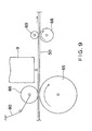
- paper feeding is effected by the paper-feeding roller 65 driven by the PF motor 1 and the follower roller 66 as already explained with reference to Figs. 5 and 6.
- the follower roller 66 is configured to urge the paper sheet 50 onto the paper-feeding roller 65 during the paper feeding motion with the aid of the spring 80 as shown in Fig. 9.
- United States Patent N°. 4 777 609 discloses a conventional deceleration control of the motor of the printer. As shown in Figs. 20, 25, 28 and 30 of the US Patent D1, however, the voltage is continuously applied to the motor until the print head reaches to the stop target position. Accordingly, the US Patent D1 does not provide any solution for the above-mentioned problem.
- United States Patent N°. 5 894 315 discloses another deceleration control of the motor of the printer in that the interrupt command signal INT7 is inputted when the moving velocity of the carriage is decelerated to the stop-prediction velocity or lower velocity, and as a result, the carriage is stopped at or nearby the terminal end of the deceleration region (See column 9, lines 11-30 in D2).
- the US Patent D2 may provide one kind of solutions for the above-mentioned problem, but it cannot provide a precise deceleration control having enough accuracy, because the interrupt command signal INT7 is inputted when period of the pulse signals P1 and P2, which are output signals of encoder, are excessively long, that is, when the moving velocity of the carriage is equal to or lower than the stop-prediction velocity.
- the US Patent D2 does not detect real-time velocity or current velocity of the carriage with high accuracy, instead, it merely detects whether period of the pulse signals P1 and P2 are excessively long or not.
- a motor control apparatus is defined in the appended claim 1.
- a motor control method according to the invention is defined in appended claim 11. Further features are recited in the claims dependent from claim 11.
- the recording medium of a computer program according to the invention is characterized in having recorded a computer program for executing in a computer system one of the above-summarized motor control methods according to the invention.
- Fig. 11 is a block diagram that shows configuration of a motor control apparatus according to the first embodiment of the invention
- Fig. 12 is a flow chart that shows procedures of a motor control method according to the first embodiment of the invention
- Fig. 13 is a graph that shows a relation between the current speed of the motor at a speed measuring position and the time (number of pulses) for instructing deenergization.
- the motor control apparatus and the motor control method according to the first embodiment of the invention are configured to predetermine a speed measuring position upstream of a target stop position of a motor-driven subject by a predetermined distance and then instruct deenergization of the motor after a period of time corresponding to the current speed of the motor that is measured when the motor-driven subject reaches the speed measuring position. That is, it is precisely predicted from the current speed of the motor upon arrival of the motor-driven subject at the speed measuring position at which point of time, before arrival at the target stop position of the subject to be driven, the motor should be energized to ensure that the motor-driven subject stops just at the target stop position, and deenergization of the motor is instructed at the point of time determined by the prediction.
- the time from measurement of the current speed of the motor to the instruction of deenergization of the motor is measured with the number of encoder pulses or the number of clock pulses.
- Fig. 11 Configuration of the motor control apparatus according to the first embodiment of the invention shown in Fig. 11 is for the case in which the motor to be controlled is a DC motor. More specifically, a stop position prediction controller 60 is added to a typical DC unit 6, and the stop position prediction controller 60 is supplied with outputs of a position calculator 6a and a speed calculator 6d and an output of and encoder 11 or a clock. Although Fig. 11 illustrates that the stop position prediction controller 60 is supplied with both an output of the encoder 11 and a clock, it may be configured, if necessary, to be supplied with one of the output of the encoder 11 and the clock.
- the stop position prediction controller 60 has the function as a counter to measure a period of time by means of the number of encoder pulses or the number of clock pulses.
- a speed measuring position is previously determined upstream of a target stop position of a motor-driven subject by a predetermined distance. Additionally, in response to the current speed of the motor that is measured when the motor-driven subject reaches the speed measuring position, concerning how long in time after measurement of the current speed of the motor the motor should be energized to ensure the motor-driven subject stops just at the target stop position, sufficient data are collected by precise measurement through tests, simulation, and so on, and the data are previously stored in an appropriate means.
- a memory may be provided in the stop position prediction controller 60, for example, and the data may be stored in that memory.
- a memory may be provided outside the stop position prediction controller 60, and the data may be stored in the memory and may be read out into the stop position prediction controller 60.
- an exclusive memory may be provided to read out data therefrom into the stop position prediction controller 60, or the data may be stored in any of ASIC 20, PROM 21, RAM 22 and EPROM 23 shown in Fig. 1 such that data can be readout into the stop position prediction controller 60 through CPU 16.
- the graph of Fig. 13 shows a relation between the current speed of the motor at a speed measuring position and the duration of time from measurement of the current speed of the motor to giving instruction of deenergization of the motor (which may be called, hereinafter, "deenergization instruction time" (number of pulses).
- deenergization instruction time is measured by means of the number of encoder pulses or the number of clock pulses, as stated above.
- the speed is divided into five values, VO1, V02, V03, V04 and V05 (V01 ⁇ V02 ⁇ V03 ⁇ V04 ⁇ V05). Then, the deenergization instruction time (number of pulses) is determined which division the measured current speed of the motor is contained in.
- deenergization of the motor is instructed five pulses later; if higher than V01 and not higher than V02, two pulses later; if higher than V02 and not higher than V03, three pulses later; if higher than V03 and not higher than V04, two pulses later, if higher than V04 and not higher than V05, one pulse later; and if higher than V05, immediately.
- the deenergization instruction time varies substantially in inverse proportion to the current speed of the motor upon arrival of the motor-driven subject at the speed measuring position.
- the deenergization instruction time is measured by way of the number of encoder pulses or the number of clock pulses, the deenergization instruction time varies stepwise. Further, even when a maximum value is used, it is important that the deenergization instruction time is determined to ensure that the deenergization of the motor is certainly instructed before the motor-driven subject reaches the target stop position.
- encoder pulses are used for measurement also during actual control operations. If the deenergization instruction time is measured with the number of clock pulses for collection of data through tests, simulation, or the like, then clock pulses are used for measurement also during actual control operations. This is because, although intervals of clock pulses are always constant as being set previously, encoder pulses vary with the current speed of the motor and need matching.
- the stop position prediction controller 60 is used to measure the deenergization instruction time by way of the number of encoder pulses or the number of clock pulses, so it should have the function as a counter as stated above.
- the motor control apparatus and the motor control method according to the invention are prepared for actual use.
- the stop position prediction controller 60 monitors through output of the position calculator 6a whether the motor-driven subject has reached the speed measuring position or not (step S1). When arrival at the speed measuring position is confirmed, the stop position prediction controller 60 measures the current speed of the motor from the output of the speed calculator 6d (step S2).
- the stop position prediction controller 60 determines how many pulses later it should instruct deenergization of the motor, that is, determined the deenergization instruction time (step S3). Data on the relation between the current speed of the motor and the deenergization instruction time is always prepared for use by the stop position prediction controller 60.
- the stop position prediction controller 60 starts measurement immediately after determining the deenergization instruction time. That is, it counts the number of pulses of the output of the encoder 11 or the clock, which is selected previously. When the count value of the pulses reaches the number of pulses corresponding to the determined deenergization instruction time, the stop position prediction controller 60 supplies a D/A converter 6j with a deenergization instruction signal that instructs deenergization of the motor (step S4). As a result, the motor is deenergized and decelerates, and the motor-driven subject stops at the target stop position. For more precise positioning of the motor-driven subject at the target stop position, a braking means such as short brake, for example, may be used in combination upon the stop control.
- a braking means such as short brake, for example, may be used in combination upon the stop control.
- the motor control apparatus and the motor control method according to the first embodiment of the invention stop the motor and the motor-driven sub j ect by measuring the current speed of the motor upon arrival of the motor-driven subject at the speed measuring position upstream of the target stop position of the motor-driven subject by a predetermined distance and controlling to instruct deenergization of the motor after the deenergization instruction time corresponding to the current speed of the motor at the position upstream of the target stop position of the motor-driven subject, it is possible to prevent influences from fluctuation in motor speed to the positioning accuracy about the stop position of the motor-driven subject and to improve the positioning accuracy regarding the stop position of the motor-driven subject.
- the motor control apparatus being a DC motor control apparatus, i.e. as the motor to be controlled being a DC motor.
- the motor control apparatus and the motor control method are similarly applicable also when the motor to be controlled is a stepping motor, AC motor, or the like.
- the configuration includes a position calculator responsive to encoder pulses output from the encoder in response to rotation of the motor to calculate and output the current position of the motor-driven subject; a speed calculator responsive to the encoder pulses to calculate and output the current speed of the motor; and a stop position prediction controller responsive to outputs of the position calculator and the speed calculator to output the deenergization instruction signal that instructs deenergization of the motor a predetermined period of time later than arrival of the motor-driven subject at the speed measuring position, which corresponds to the current speed of the motor upon arrival of the motor-driven subject at the speed measuring position upstream of the target stop position of the motor-driven subject by a predetermined distance.
- Destination of the deenergization instruction signal is different depending upon the motor to be controlled, but it is always the same that the destination of the deenergization instruction signal is the drive signal generator that generates a drive signal for driving the motor.
- the drive signal generator is a component that corresponds to the D/A converter in the configuration in which the motor to be controlled is a DC motor.
- the motor to be controlled is mainly a paper feeding motor, but it may be a carriage motor as well.
- the deenergization instruction time may be changed not only in accordance with the current speed of the motor upon arrival of the motor-driven subject at the speed measuring position, but also in accordance with other conditions such as remaining quantity of ink, nature of the printing paper, frequency of use of the printer, ambient temperature, ambient humidity, etc.
- sensors for detecting predetermined conditions to be used for changing the deenergization instruction time such as nature of the printing paper, frequency of use of the printer, ambient temperature, ambient humidity, and so on, may be attached to the paper feeding mechanism.
- the nature of the printing paper instead of detecting it with a sensor, it may be treated as one of predetermined conditions used for changing the deenergization instruction time on the part of the motor control apparatus, and the motor control apparatus may be preset in accordance with the printing paper to be used.
- the motor to be controlled is the carriage motor
- sensors for detecting predetermined conditions used for changing the deenergization instruction time such as remaining quantity of ink, frequency of use of the printer, ambient temperature, ambient humidity, and so on, are attached to the carriage 3.
- predetermined conditions detected by the sensors are sent to the stop position prediction controller 60, and the stop position prediction controller 60 first makes appropriate correction based on the predetermined conditions received before determining the deenergization instruction time in response to the current speed of the motor upon arrival of the motor-driven subject at the speed measuring position, and thereafter determines the deenergization instruction time.
- predetermined conditions detected by the sensors may be sent to the memory storing data on the deenergization instruction time, and the data about the deenergization instruction time may be modified by correction based on the predetermined conditions.
- the stop position prediction controller 60 determined the deenergization instruction time based on the data modified, in response to the current speed of the motor upon arrival of the motor-driven subject at the speed measuring position.
- conditions for determining the deenergization instruction time by the motor control apparatus and the motor control method according to the first embodiment of the invention are not limited to the current speed of the motor upon arrival of the motor-driven subject at the speed measuring position, but various conditions may be used. Means for detecting those conditions may be provided previously like the above-mentioned example.
- more generalized configuration of the motor control apparatus is characterized in comprising the stop position prediction controller that instructs deenergization of the motor after arrival of the motor-driven subject at a predetermined position upstream a target stop position of the motor-driven subject by a predetermined distance, by a predetermined period of time corresponding to a predetermined condition upon arrival of the motor-driven subject at the predetermined position.
- more generalized configuration of the motor control method according to the first embodiment of the invention is characterized in instructing deenergization of the motor after arrival of the motor-driven subject at a predetermined position upstream a target stop position of the motor-driven subject by a predetermined distance, by a predetermined period of time corresponding to a predetermined condition upon arrival of the motor-driven subject at the predetermined position.
- Fig. 14 is a block diagram that shows configuration of a motor control apparatus according to the second embodiment of the invention
- Fig. 15 is a block diagram that shows a specific example of a current value signal generator of the motor control apparatus according to the second embodiment of the invention
- Fig. 16 is a flow chart that shows behaviors of the motor control apparatus according to the second embodiment of the invention, that is, procedures of a motor control method according to the second embodiment of the invention
- Fig. 17 is a timing chart that explains behaviors of the motor control apparatus according to the second embodiment of the invention.
- the motor control apparatus 6 has a configuration in which a pulse counter 6p and a current value signal generator 6q are added to the conventional motor control apparatus 6 shown in Fig. 7.
- the part of the motor control apparatus 6 other than the pulse counter 6p and the current value signal generator 6q was already explained, its explanation is omitted here.
- the current value signal generator 6q is made up of a current value determiner 71 and a detector 72 as shown in Fig. 15.
- the pulse counter 6p starts counting the risings and tailing edges of output pulses ENC-A, ENC-B of the encoder 13 (see the step F2 of Fig. 16). If the count value is still lower than a predetermined value (for example, 5) even after a predetermined period of time (see the step F3), it is considered that the sheet 50 is held in the predetermined extent between the paper feeding roller 65 and the follower roller 66. Thus the control is finished, and a printing process takes place.
- a predetermined value for example, 5
- the reason why the value 5 is selected as the predetermined value lies in that the DC motor is difficult to stop at the position where the positional deviation zero and it is usually stopped within the range where the positional deviation is ⁇ 3.
- an instruction signal is sent from the pulse counter 6p to the current value determiner 71 of the current value signal generator 6q. Then, the current value determiner 71 of the current value signal generator 6q determines a current value signal, which will become a predetermined current value I 1 necessary for rotating the PF motor 1 in the reverse direction, and sends it to the D/A converter 6j (see the step F4 of Fig. 15).
- the predetermined current value I 1 is determined in accordance with thickness of the sheet 50, for example, and it may be the minimum value among absolute values of current values causing the PF motor 1 to rotate in the reverse direction, for example. It is previously obtained by experiments.
- the current value signal which will become the predetermined current value I 1 is converted to an analog current instruction value by the D/A converter 6j, and sent out to the driver 2. Then the driver 2 drives the PF motor 1 such that the current value additionally applied to the PF motor 1 becomes I 1 . At that time, the adder 6i and the acceleration controller 6m do not work, and their outputs are all zero.
- the current value signal that will become the said predetermined current value I 1 is output from the current value signal generator 6q when the output pulse ECN-B of the encoder 13 is the "H" level, i.e., from the point of time t 1 to t 2 shown in Fig. 17.
- the PF motor 1 rotates in the reverse direction or stops, Whether the PF motor 1 has stopped or not is detected by the detector 72 of he current value signal generator 6q from output pulses of the encoder 13 (see the step F5 of Fig. 16).
- a current value signal of a current value I 2 that is smaller than the preceding one but equal in sign is determined by the current value signal determiner 71 of the current value signal generator 6q (see the point of time t 3 of Fig. 17), and sent to the D/A converter 6j (see the step F6 of Fig. 16).
- the current value signal which is the current value I 2
- step F5 if the sheet is judged to have stopped, it is considered that the perimeter of the sheet 50 is held in the predetermined extend (extent x shown in Fig. 10) between the paper feeding roller 65 and the follower roller 66, and a signal is sent from the detector 72 to the current value determiner 71 which thereafter continuously output the current value signal (see the point of time t 5 of shown in Fig. 17).
- the current value determined by the current value determiner 71 is preferably extracted from a table that store values previously obtained through experiments, or the like.
- the perimeter of the sheet 50 can be held within the predetermined extent between the paper feeding roller 65 and the follower roller 66, and a wide area of the sheet to near its perimeters can be used for printing.
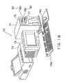
- Fig. 18 is an explanatory diagram that illustrate configuration in external appearance of a recording medium having recorded a program for executing a motor control method according to the invention and a computer system in which the recording medium is used
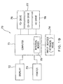
- Fig. 19 is a block diagram that shows configuration of the computer system shown in Fig. 18.
- the computer system 70 shown in Fig. 18 is made up of a computer main body 71 housed in a casing like a mini tower, for example, a display 72 such as CRT (cathode ray tube), plasma display, liquid crystal display, or the like, a printer 73 as a record output apparatus, a key board 74a and a mouse 74b as input devices, a flexible disk drive 76, and a CD-ROM drive 77.
- Fig. 19 illustrates configuration of the computer system 70 as a block diagram, and the casing that houses the computer main body 71 further contains internal memory 75 such as RAM (random access memory), for example, and external memory like a hard disk drive unit 78, for example.
- RAM random access memory
- the recording medium having recorded a computer program for executing the motor control method according to the invention is used on the computer system 70.
- Used as the recording medium is a flexible disk 81 or CD-ROM (read only memory) 82, for example, but other means may be used, such as MO (magneto-optical) disk, DVD (digital versatile disk), other optical recording disks, card memory, magnetic tape, and so on.
Landscapes
- Character Spaces And Line Spaces In Printers (AREA)
- Control Of Electric Motors In General (AREA)
- Preparation Of Compounds By Using Micro-Organisms (AREA)
- Delivering By Means Of Belts And Rollers (AREA)
- Control Of Direct Current Motors (AREA)
Claims (13)
- Motorsteuervorrichtung zum Steuern eines Papierzuführ- oder Schlittenmotors eines Druckers, die aufweist:eine Anhalt-Position-Vorhersage-Steuereinheit (60), um eine Stromunterbrechung zu dem Motor eine vorgegebene Zeitperiode später als die Ankunft eines Gegenstands, der durch den Motor angetrieben werden soll, an einer Geschwindigkeitsmessposition, und vor der Ankunft des Gegenstands, der angetrieben werden soll, an der Soll-Anhalt-Position anzuweisen, wobei die vorgegebene Zeitperiode einer momentanen Geschwindigkeit des Motors und der Ankunft des Gegenstands, der angetrieben werden soll, an der Geschwindigkeitsmessposition entspricht, und wobei die Geschwindigkeitsmessposition einen vorgegebenen Abstand vor einer Soll-Anhalt-Position des Gegenstands, der angetrieben werden soll, liegt; und einen Datenspeicherbereich (20, 21, 22, 23), um Daten über Beziehungen zwischen der momentanen Geschwindigkeit des Motors und der Ankunft des Gegenstands, der angetrieben werden soll, an der Geschwindigkeitsmessposition, und der vorgegebenen Zeitperiode, zu speichern.
- Motorsteuervorrichtung nach Anspruch 1, wobei die vorgegebene Zeitperiode im Wesentlichen in einem umgekehrten Verhältnis zu der momentanen Geschwindigkeit des Motors unter Ankunft des Gegenstands, der angetrieben werden soll, an der Geschwindigkeitsmessposition variiert.
- Motorsteuervorrichtung nach Anspruch 1 oder 2, wobei die vorgegebene Zeitperiode auf einen Wert bestimmt ist, der sicherstellt, dass der Gegenstand, der angetrieben werden soll, an der Soll-Anhalt-Position anhält.
- Motorsteuervorrichtung nach Anspruch 1, die weiterhin aufweist:eine Positions-Berechnungseinrichtung (6a) zum Berechnen und Ausgeben einer momentanen Position eines Gegenstands, der durch einen Motor angetrieben werden soll, auf der Basis von Codierer-Impulsen, die von einem Codierer in Abhängigkeit einer Drehung des Motors ausgegeben sind;eine Geschwindigkeitsberechnungseinrichtung (6d) zum Berechnen und Ausgeben einer momentanen Geschwindigkeit des Motors auf der Basis der Codierer-Impulse; undeine Anhalt-Position-Vorhersage-Steuereinheit (60), um ein Stromunterbrechungs-Anweisungssignal auszugeben, das eine Stromunterbrechung zu dem Motor anweist, eine vorgegebene Zeitperiode später als die Ankunft des Gegenstands, der angetrieben werden soll, an der Geschwindigkeitsmessposition, wobei die vorgegebene Zeitperiode der momentanen Geschwindigkeit des Motors unter Ankunft des Gegenstands, der angetrieben werden soll, an der Geschwindigkeitsmessposition entspricht, und wobei die Geschwindigkeitsmessposition an einem vorgegebenen Abstand vor der Soll-Anhalt-Position des Gegenstands, der angetrieben werden soll, liegt.
- Motorsteuervorrichtung nach Anspruch 4, wobei die vorgegebene Zeitperiode so bestimmt ist, dass sie eine Dauer hat, die sicherstellt, dass das Stromunterbrechungs-Anweisungssignal vor der Ankunft des Gegenstands, der angetrieben werden soll, an der Soll-Anhalt-Position ausgegeben wird.
- Motorsteuervorrichtung nach Anspruch 4 oder 5, wobei die Anhalt-Position-Vorhersage-Steuervorrichtung die vorgegebene Zeitperiode durch Zählen der Anzahl der Codierer-Impulse misst.
- Motorsteuervorrichtung nach einem der Ansprüche 4 bis 6, wobei die Anhalt-Position-Vorhersage-Steuervorrichtung die vorgegebene Zeitperiode durch Zählen der Anzahl von Impulsen eines vorgegebenen Takts misst.
- Motorsteuervorrichtung nach einem der Ansprüche 4 bis 7, wobei die Bestimmungsstelle für das Stromunterbrechungs-Anweisungssignal ein Ansteuersignal-Generator ist, der ein Ansteuersignal für ein drehbares Antreiben des Motors erzeugt.
- Motorsteuervorrichtung nach einem der Ansprüche 4 bis 8, wobei die vorgegebene Zeitperiode im Wesentlichen in einem umgekehrten Verhältnis zu der momentanen Geschwindigkeit des Motors und der Ankunft des Gegenstands, der angetrieben werden soll, an der Geschwindigkeitsmessposition variiert.
- Motorsteuervorrichtung nach Anspruch 4, wobei die vorgegebene Zeitperiode auf einen Wert bestimmt wird, der sicherstellt, dass der Gegenstand, der angetrieben werden soll, an der Soll-Anhalt-Position anhält.
- Motorsteuerverfahren zum Steuern eines Papierzuführungs- oder Schlittenmotors eines Druckers, das so ausgelegt ist, um eine Stromunterbrechung zu dem Motor eine vorgegebene Zeitperiode später als die Ankunft eines Gegenstands, der durch den Motor angetrieben werden soll, an einer Geschwindigkeitsmessposition und vor einer Ankunft des Gegenstands, der angetrieben werden soll, an der Soll-Anhalt-Position anzuweisen, wobei die vorgegebene Zeitperiode einer momentanen Geschwindigkeit des Motors und der Ankunft des Gegenstands, der angetrieben werden soll, an der Geschwindigkeitsmessposition entspricht, und wobei die Geschwindigkeitsmessposition einen vorgegebenen Abstand vor einer Soll-Anhalt-Position des Gegenstands, der angetrieben werden soll, liegt,
wobei, für den Zweck einer Bestimmung der vorgegebenen Zeitperiode, Daten zuvor gesammelt und gespeichert werden, die sich auf Beziehungen zwischen der momentanen Geschwindigkeit des Motors und der Ankunft des Gegenstands, der angetrieben werden soll, an der Geschwindigkeitsmessposition und der vorgegebenen Zeitperiode beziehen. - Motorsteuerverfahren nach Anspruch 11, das aufweist:einen ersten Vorgang (S1) zum Messen einer momentanen Position eines Gegenstands, der durch einen Motor angetrieben werden soll, und zum Überwachen, ob der Gegenstand, der angetrieben werden soll, eine Geschwindigkeitsmessposition erreicht hat;einen zweiten Vorgang (S2) zum Messen der momentanen Geschwindigkeit des Motors und der Ankunft des Gegenstands, der angetrieben werden soll, an der Geschwindigkeitsmessposition;einen dritten Vorgang (S3) zum Bestimmen einer vorgegebenen Zeitperiode; undeinen vierten Vorgang (S4) zum Anweisen einer Stromunterbrechung zu dem Motor um die vorgegebene Zeitperiode später als die Ankunft des Gegenstands, der angetrieben werden soll, an der Geschwindigkeitsmessposition.
- Computerprogramm-Code zum Ausführen durch einen Prozessor in einem Computersystem (70), wobei der Computerprogramm-Code für die Ausführung des Motorsteuerverfahrens entsprechend Anspruch 11 oder Anspruch 12 durch Steuern einer Anhalt-Position-Vorhersage-Steuervorrichtung (60) zum Anweisen der Stromunterbrechung dient.
Priority Applications (1)
| Application Number | Priority Date | Filing Date | Title |
|---|---|---|---|
| EP05076859A EP1602504B1 (de) | 2000-03-03 | 2001-03-02 | Motorsteuerungsvorrichtung und -verfahren |
Applications Claiming Priority (4)
| Application Number | Priority Date | Filing Date | Title |
|---|---|---|---|
| JP2000058486 | 2000-03-03 | ||
| JP2000058486A JP3871181B2 (ja) | 2000-03-03 | 2000-03-03 | 印刷制御装置および制御方法ならびに印刷制御プログラムを記録した記録媒体 |
| JP2000058645 | 2000-03-03 | ||
| JP2000058645A JP3780804B2 (ja) | 2000-03-03 | 2000-03-03 | モータ制御装置及び制御方法 |
Related Child Applications (1)
| Application Number | Title | Priority Date | Filing Date |
|---|---|---|---|
| EP05076859A Division EP1602504B1 (de) | 2000-03-03 | 2001-03-02 | Motorsteuerungsvorrichtung und -verfahren |
Publications (2)
| Publication Number | Publication Date |
|---|---|
| EP1129856A1 EP1129856A1 (de) | 2001-09-05 |
| EP1129856B1 true EP1129856B1 (de) | 2007-01-17 |
Family
ID=26586705
Family Applications (2)
| Application Number | Title | Priority Date | Filing Date |
|---|---|---|---|
| EP01400549A Expired - Lifetime EP1129856B1 (de) | 2000-03-03 | 2001-03-02 | Motorsteuerungsvorrichtung und -verfahren |
| EP05076859A Expired - Lifetime EP1602504B1 (de) | 2000-03-03 | 2001-03-02 | Motorsteuerungsvorrichtung und -verfahren |
Family Applications After (1)
| Application Number | Title | Priority Date | Filing Date |
|---|---|---|---|
| EP05076859A Expired - Lifetime EP1602504B1 (de) | 2000-03-03 | 2001-03-02 | Motorsteuerungsvorrichtung und -verfahren |
Country Status (4)
| Country | Link |
|---|---|
| US (2) | US6600286B2 (de) |
| EP (2) | EP1129856B1 (de) |
| AT (1) | ATE360534T1 (de) |
| DE (2) | DE60128164T2 (de) |
Families Citing this family (34)
| Publication number | Priority date | Publication date | Assignee | Title |
|---|---|---|---|---|
| JP3921928B2 (ja) * | 1999-09-24 | 2007-05-30 | セイコーエプソン株式会社 | 印刷制御装置および印刷制御方法ならびに印刷制御プログラムを記録した記録媒体 |
| DE60128164T2 (de) * | 2000-03-03 | 2008-03-06 | Seiko Epson Corp. | Motorsteuerungsvorrichtung und -verfahren |
| EP1286237A1 (de) * | 2001-07-20 | 2003-02-26 | Valtronic S.A. | Verfahren zur Steurerung eines Motors |
| JP3673745B2 (ja) * | 2001-10-01 | 2005-07-20 | キヤノン株式会社 | 制御装置及びその方法、記録装置及びその制御方法 |
| JP3741071B2 (ja) * | 2002-03-29 | 2006-02-01 | ブラザー工業株式会社 | 給紙装置 |
| JP2004237501A (ja) * | 2003-02-04 | 2004-08-26 | Brother Ind Ltd | キャリッジ駆動装置及びモータ制御方法 |
| JP4144426B2 (ja) * | 2003-05-02 | 2008-09-03 | セイコーエプソン株式会社 | Dcモータを用いたプリンタ及びその制御方法 |
| WO2004106075A1 (en) * | 2003-05-30 | 2004-12-09 | Ricoh Company, Ltd. | Image forming apparatus |
| AU2004281370A1 (en) * | 2003-08-29 | 2005-04-28 | Engineered Support Systems, Inc. | Electronically programmable actively damped sensor mount |
| US7821216B2 (en) * | 2003-09-12 | 2010-10-26 | Brother Kogyo Kabushiki Kaisha | Motor control method and control device |
| JP4059213B2 (ja) * | 2004-02-27 | 2008-03-12 | ブラザー工業株式会社 | モータ制御装置およびモータ制御方法 |
| JP4552541B2 (ja) * | 2004-07-09 | 2010-09-29 | ブラザー工業株式会社 | キャリッジ駆動制御装置及び方法 |
| JP2006201148A (ja) * | 2004-12-22 | 2006-08-03 | Toshiba Mach Co Ltd | 信号処理装置、信号処理方法、信号処理プログラム、信号処理プログラムを記録した記録媒体、速度検出装置、サーボ機構 |
| JP4760090B2 (ja) * | 2005-03-30 | 2011-08-31 | ブラザー工業株式会社 | 搬送装置及び画像形成装置 |
| JP4470795B2 (ja) * | 2005-03-30 | 2010-06-02 | ブラザー工業株式会社 | 画像形成装置 |
| US8004724B2 (en) * | 2005-12-05 | 2011-08-23 | Canon Kabushiki Kaisha | Method and apparatus for image reading with synchronized readout and lighting control |
| JP2007330000A (ja) * | 2006-06-06 | 2007-12-20 | Seiko Epson Corp | モータ制御装置 |
| US7868568B2 (en) * | 2007-02-28 | 2011-01-11 | Brother Kogyo Kabushiki Kaisha | Motor driving device |
| US20090057997A1 (en) * | 2007-08-31 | 2009-03-05 | Seiko Epson Corporation | Printer, drive control method, and motor control program for printer |
| US7719224B2 (en) * | 2007-09-28 | 2010-05-18 | Rockwell Automation Technologies, Inc. | Simulated encoder pulse output system and method |
| US8310178B2 (en) * | 2009-02-27 | 2012-11-13 | Canon Kabushiki Kaisha | Motor control apparatus and image forming apparatus |
| JP5177195B2 (ja) * | 2010-09-21 | 2013-04-03 | 株式会社デンソー | 回転機の制御装置 |
| JP5707129B2 (ja) * | 2010-12-28 | 2015-04-22 | Thk株式会社 | モータ制御装置、モータ制御方法、及び制御プログラム |
| JP5713031B2 (ja) * | 2012-02-06 | 2015-05-07 | 株式会社リコー | モータ制御装置、モータシステム、搬送装置、画像形成装置、モータ制御方法およびプログラム |
| US20140055064A1 (en) * | 2012-08-27 | 2014-02-27 | Allegro Microsystems, Inc. | Systems and Methods for Controlling Motor Speeds |
| JP5724977B2 (ja) * | 2012-09-20 | 2015-05-27 | 株式会社デンソー | ブラシレスモータの制御システム |
| JP6650720B2 (ja) * | 2015-10-09 | 2020-02-19 | キヤノン株式会社 | 記録装置、記録装置の制御方法、及びプログラム |
| CN108062038A (zh) * | 2016-11-08 | 2018-05-22 | 广州奥睿智能科技有限公司 | 舵机控制方法、控制系统和舵机 |
| JP2019030033A (ja) * | 2017-07-25 | 2019-02-21 | 東芝テック株式会社 | モータ制御装置及びプリンタ |
| JP7052255B2 (ja) * | 2017-08-25 | 2022-04-12 | コニカミノルタ株式会社 | 画像形成装置 |
| CN109109474B (zh) * | 2018-09-19 | 2021-07-13 | 南阳柯丽尔科技有限公司 | 打印设备的控制方法及系统 |
| CN109849534B (zh) * | 2018-12-29 | 2021-03-23 | 厦门汉印电子技术有限公司 | 一种照片打印机、打印方法、装置和存储介质 |
| CN115683196B (zh) * | 2022-11-17 | 2025-02-18 | 遨博(北京)智能科技股份有限公司 | 一种自动化测试编码器方法及系统 |
| CN116520901B (zh) * | 2023-04-04 | 2026-04-07 | 北京环境特性研究所 | 高精度速率转台的伺服控制设备、系统及方法 |
Family Cites Families (16)
| Publication number | Priority date | Publication date | Assignee | Title |
|---|---|---|---|---|
| US3950685A (en) * | 1974-04-25 | 1976-04-13 | Lrc, Inc. | Dc motor position controller |
| US4369402A (en) * | 1980-07-22 | 1983-01-18 | Xerox Corporation | Motion damping apparatus |
| US4591774A (en) * | 1981-05-21 | 1986-05-27 | Dataproducts Corporation | High performance incremental motion system using a closed loop stepping motor |
| US4460968A (en) * | 1981-10-16 | 1984-07-17 | International Business Machines Corporation | Print head motor control with stop distance compensation |
| US4777609A (en) | 1985-12-11 | 1988-10-11 | International Business Machines Corporation | Print head motor control system having steady state velocity compensation |
| JPH0729454B2 (ja) * | 1990-04-10 | 1995-04-05 | 旭光学工業株式会社 | プリンタの書き出し位置調整機構 |
| JP3204664B2 (ja) * | 1990-09-17 | 2001-09-04 | オリンパス光学工業株式会社 | モータの駆動制御装置 |
| US5057859A (en) * | 1990-11-23 | 1991-10-15 | Olympus Optical Co., Ltd. | Camera having high-precision stop function for movable unit |
| JPH05338306A (ja) * | 1992-06-11 | 1993-12-21 | Fuji Xerox Co Ltd | シリアルプリンタ |
| JPH07137376A (ja) * | 1993-06-30 | 1995-05-30 | Asahi Optical Co Ltd | 用紙搬送機構 |
| JP3555669B2 (ja) * | 1995-11-09 | 2004-08-18 | ブラザー工業株式会社 | 記録装置 |
| EP0807528B1 (de) * | 1996-05-15 | 2001-12-12 | Océ-Technologies B.V. | Verfahren und System zur Detektierung einer Wagenlage |
| JP3736010B2 (ja) * | 1997-03-19 | 2006-01-18 | 富士ゼロックス株式会社 | 印刷装置及び用紙送り装置 |
| US5826157A (en) * | 1997-07-31 | 1998-10-20 | Xerox Corporation | Sychronized paper feeding across module boundaries with timed clock ticks |
| ATE410309T1 (de) * | 1999-12-24 | 2008-10-15 | Seiko Epson Corp | Vorrichtung und verfahren zur motorsteuerung |
| DE60128164T2 (de) * | 2000-03-03 | 2008-03-06 | Seiko Epson Corp. | Motorsteuerungsvorrichtung und -verfahren |
-
2001
- 2001-03-02 DE DE60128164T patent/DE60128164T2/de not_active Expired - Fee Related
- 2001-03-02 US US09/796,429 patent/US6600286B2/en not_active Expired - Fee Related
- 2001-03-02 EP EP01400549A patent/EP1129856B1/de not_active Expired - Lifetime
- 2001-03-02 DE DE60126001T patent/DE60126001T2/de not_active Expired - Fee Related
- 2001-03-02 AT AT05076859T patent/ATE360534T1/de not_active IP Right Cessation
- 2001-03-02 EP EP05076859A patent/EP1602504B1/de not_active Expired - Lifetime
-
2003
- 2003-05-27 US US10/445,344 patent/US6756760B2/en not_active Expired - Fee Related
Also Published As
| Publication number | Publication date |
|---|---|
| US20030205982A1 (en) | 2003-11-06 |
| US6756760B2 (en) | 2004-06-29 |
| DE60128164T2 (de) | 2008-03-06 |
| ATE360534T1 (de) | 2007-05-15 |
| EP1602504B1 (de) | 2007-04-25 |
| EP1602504A3 (de) | 2005-12-14 |
| DE60126001D1 (de) | 2007-03-08 |
| US6600286B2 (en) | 2003-07-29 |
| EP1129856A1 (de) | 2001-09-05 |
| EP1602504A2 (de) | 2005-12-07 |
| DE60128164D1 (de) | 2007-06-06 |
| US20010035724A1 (en) | 2001-11-01 |
| DE60126001T2 (de) | 2007-06-14 |
Similar Documents
| Publication | Publication Date | Title |
|---|---|---|
| EP1129856B1 (de) | Motorsteuerungsvorrichtung und -verfahren | |
| EP1681173B1 (de) | Vorrichtung und Verfahren zur Motorsteuerung | |
| EP1124320B1 (de) | Verfahren und Vorrichtung zur Motorsteuerung | |
| EP1072425B1 (de) | Steuereinheit und Verfahren zum Steuern eines Motors zur Vewendung in einem Drucker und Steuerungsprogramm speicherndes Speichermedium | |
| JP2001169584A (ja) | プリンタ用モータの制御装置およびその制御方法ならびに制御プログラムを記録した記録媒体 | |
| JP3812417B2 (ja) | プリンタ制御方法及びプリンタ制御装置 | |
| JP3832174B2 (ja) | モータ制御装置及び制御方法 | |
| JP3780804B2 (ja) | モータ制御装置及び制御方法 | |
| US6310459B1 (en) | DC motor control device and control method | |
| JP4362815B2 (ja) | プラテンギャップ調整装置及び印刷装置並びにモータ制御装置 | |
| EP1080928B1 (de) | Steuereinheit und Verfahren zur Steuerung eines Motors für einen Drucker und Steuerungsprogramm speicherndes Speichermedium | |
| JP3757834B2 (ja) | モータ制御装置及びプリンタ | |
| JP4026330B2 (ja) | モータ制御方法、モータ制御装置、プリンタ、コンピュータプログラム、及び、コンピュータシステム | |
| JP4306185B2 (ja) | プリンタ制御装置、プリンタ制御方法及びコンピュータプログラム | |
| JP3705061B2 (ja) | モータの制御装置およびその制御方法ならびにモータの制御プログラムを記録した記録媒体 | |
| JP2005231243A (ja) | プリンタ制御装置及びプリンタ制御方法並びにプリンタ | |
| JP4026331B2 (ja) | モータ駆動方法、モータ駆動装置、プリンタ、コンピュータプログラム、及び、コンピュータシステム | |
| JP3818496B2 (ja) | プリンタ制御装置及びプリンタ制御方法 | |
| JP2001142537A (ja) | プリンタ用モータの制御装置および制御方法ならびに制御プログラムを記録した記録媒体 | |
| JP4003721B2 (ja) | プリンタ | |
| JP3885559B2 (ja) | プリンタ制御方法及びプリンタ制御装置 | |
| JP2005200222A (ja) | 印刷制御装置および制御方法ならびに印刷制御プログラムを記録した記録媒体 | |
| JP2001246799A (ja) | 印刷制御装置および制御方法ならびに印刷制御プログラムを記録した記録媒体 | |
| JP2005178142A (ja) | プリンタ制御装置及びプリンタ制御方法並びにプリンタ | |
| JP2003276258A (ja) | プリンタ制御装置及びプリンタ制御方法 |
Legal Events
| Date | Code | Title | Description |
|---|---|---|---|
| PUAI | Public reference made under article 153(3) epc to a published international application that has entered the european phase |
Free format text: ORIGINAL CODE: 0009012 |
|
| AK | Designated contracting states |
Kind code of ref document: A1 Designated state(s): AT BE CH CY DE DK ES FI FR GB GR IE IT LI LU MC NL PT SE TR |
|
| AX | Request for extension of the european patent |
Free format text: AL;LT;LV;MK;RO;SI |
|
| 17P | Request for examination filed |
Effective date: 20010925 |
|
| AKX | Designation fees paid |
Free format text: AT BE CH CY DE DK ES FI FR GB GR IE IT LI LU MC NL PT SE TR |
|
| 17Q | First examination report despatched |
Effective date: 20050223 |
|
| GRAP | Despatch of communication of intention to grant a patent |
Free format text: ORIGINAL CODE: EPIDOSNIGR1 |
|
| GRAS | Grant fee paid |
Free format text: ORIGINAL CODE: EPIDOSNIGR3 |
|
| GRAA | (expected) grant |
Free format text: ORIGINAL CODE: 0009210 |
|
| AK | Designated contracting states |
Kind code of ref document: B1 Designated state(s): AT BE CH CY DE DK ES FI FR GB GR IE IT LI LU MC NL PT SE TR |
|
| PG25 | Lapsed in a contracting state [announced via postgrant information from national office to epo] |
Ref country code: LI Free format text: LAPSE BECAUSE OF FAILURE TO SUBMIT A TRANSLATION OF THE DESCRIPTION OR TO PAY THE FEE WITHIN THE PRESCRIBED TIME-LIMIT Effective date: 20070117 Ref country code: FI Free format text: LAPSE BECAUSE OF FAILURE TO SUBMIT A TRANSLATION OF THE DESCRIPTION OR TO PAY THE FEE WITHIN THE PRESCRIBED TIME-LIMIT Effective date: 20070117 Ref country code: DK Free format text: LAPSE BECAUSE OF FAILURE TO SUBMIT A TRANSLATION OF THE DESCRIPTION OR TO PAY THE FEE WITHIN THE PRESCRIBED TIME-LIMIT Effective date: 20070117 Ref country code: NL Free format text: LAPSE BECAUSE OF FAILURE TO SUBMIT A TRANSLATION OF THE DESCRIPTION OR TO PAY THE FEE WITHIN THE PRESCRIBED TIME-LIMIT Effective date: 20070117 Ref country code: CH Free format text: LAPSE BECAUSE OF FAILURE TO SUBMIT A TRANSLATION OF THE DESCRIPTION OR TO PAY THE FEE WITHIN THE PRESCRIBED TIME-LIMIT Effective date: 20070117 Ref country code: AT Free format text: LAPSE BECAUSE OF FAILURE TO SUBMIT A TRANSLATION OF THE DESCRIPTION OR TO PAY THE FEE WITHIN THE PRESCRIBED TIME-LIMIT Effective date: 20070117 |
|
| REG | Reference to a national code |
Ref country code: GB Ref legal event code: FG4D |
|
| REG | Reference to a national code |
Ref country code: CH Ref legal event code: EP |
|
| REG | Reference to a national code |
Ref country code: IE Ref legal event code: FG4D |
|
| REF | Corresponds to: |
Ref document number: 60126001 Country of ref document: DE Date of ref document: 20070308 Kind code of ref document: P |
|
| PG25 | Lapsed in a contracting state [announced via postgrant information from national office to epo] |
Ref country code: SE Free format text: LAPSE BECAUSE OF FAILURE TO SUBMIT A TRANSLATION OF THE DESCRIPTION OR TO PAY THE FEE WITHIN THE PRESCRIBED TIME-LIMIT Effective date: 20070417 |
|
| PG25 | Lapsed in a contracting state [announced via postgrant information from national office to epo] |
Ref country code: ES Free format text: LAPSE BECAUSE OF FAILURE TO SUBMIT A TRANSLATION OF THE DESCRIPTION OR TO PAY THE FEE WITHIN THE PRESCRIBED TIME-LIMIT Effective date: 20070428 |
|
| PG25 | Lapsed in a contracting state [announced via postgrant information from national office to epo] |
Ref country code: PT Free format text: LAPSE BECAUSE OF FAILURE TO SUBMIT A TRANSLATION OF THE DESCRIPTION OR TO PAY THE FEE WITHIN THE PRESCRIBED TIME-LIMIT Effective date: 20070618 |
|
| ET | Fr: translation filed | ||
| NLV1 | Nl: lapsed or annulled due to failure to fulfill the requirements of art. 29p and 29m of the patents act | ||
| REG | Reference to a national code |
Ref country code: CH Ref legal event code: PL |
|
| PLBE | No opposition filed within time limit |
Free format text: ORIGINAL CODE: 0009261 |
|
| STAA | Information on the status of an ep patent application or granted ep patent |
Free format text: STATUS: NO OPPOSITION FILED WITHIN TIME LIMIT |
|
| 26N | No opposition filed |
Effective date: 20071018 |
|
| PG25 | Lapsed in a contracting state [announced via postgrant information from national office to epo] |
Ref country code: BE Free format text: LAPSE BECAUSE OF FAILURE TO SUBMIT A TRANSLATION OF THE DESCRIPTION OR TO PAY THE FEE WITHIN THE PRESCRIBED TIME-LIMIT Effective date: 20070117 |
|
| PG25 | Lapsed in a contracting state [announced via postgrant information from national office to epo] |
Ref country code: IE Free format text: LAPSE BECAUSE OF NON-PAYMENT OF DUE FEES Effective date: 20070302 Ref country code: MC Free format text: LAPSE BECAUSE OF NON-PAYMENT OF DUE FEES Effective date: 20070331 |
|
| PG25 | Lapsed in a contracting state [announced via postgrant information from national office to epo] |
Ref country code: IT Free format text: LAPSE BECAUSE OF FAILURE TO SUBMIT A TRANSLATION OF THE DESCRIPTION OR TO PAY THE FEE WITHIN THE PRESCRIBED TIME-LIMIT Effective date: 20070117 Ref country code: GR Free format text: LAPSE BECAUSE OF FAILURE TO SUBMIT A TRANSLATION OF THE DESCRIPTION OR TO PAY THE FEE WITHIN THE PRESCRIBED TIME-LIMIT Effective date: 20070418 |
|
| PGFP | Annual fee paid to national office [announced via postgrant information from national office to epo] |
Ref country code: GB Payment date: 20090225 Year of fee payment: 9 |
|
| PG25 | Lapsed in a contracting state [announced via postgrant information from national office to epo] |
Ref country code: CY Free format text: LAPSE BECAUSE OF FAILURE TO SUBMIT A TRANSLATION OF THE DESCRIPTION OR TO PAY THE FEE WITHIN THE PRESCRIBED TIME-LIMIT Effective date: 20070117 |
|
| PG25 | Lapsed in a contracting state [announced via postgrant information from national office to epo] |
Ref country code: LU Free format text: LAPSE BECAUSE OF NON-PAYMENT OF DUE FEES Effective date: 20070302 |
|
| PGFP | Annual fee paid to national office [announced via postgrant information from national office to epo] |
Ref country code: DE Payment date: 20090429 Year of fee payment: 9 |
|
| PG25 | Lapsed in a contracting state [announced via postgrant information from national office to epo] |
Ref country code: TR Free format text: LAPSE BECAUSE OF FAILURE TO SUBMIT A TRANSLATION OF THE DESCRIPTION OR TO PAY THE FEE WITHIN THE PRESCRIBED TIME-LIMIT Effective date: 20070117 |
|
| PGFP | Annual fee paid to national office [announced via postgrant information from national office to epo] |
Ref country code: FR Payment date: 20090211 Year of fee payment: 9 |
|
| GBPC | Gb: european patent ceased through non-payment of renewal fee |
Effective date: 20100302 |
|
| REG | Reference to a national code |
Ref country code: FR Ref legal event code: ST Effective date: 20101130 |
|
| PG25 | Lapsed in a contracting state [announced via postgrant information from national office to epo] |
Ref country code: FR Free format text: LAPSE BECAUSE OF NON-PAYMENT OF DUE FEES Effective date: 20100331 |
|
| PG25 | Lapsed in a contracting state [announced via postgrant information from national office to epo] |
Ref country code: DE Free format text: LAPSE BECAUSE OF NON-PAYMENT OF DUE FEES Effective date: 20101001 |
|
| PG25 | Lapsed in a contracting state [announced via postgrant information from national office to epo] |
Ref country code: GB Free format text: LAPSE BECAUSE OF NON-PAYMENT OF DUE FEES Effective date: 20100302 |