EP1129883B1 - Boíte-transfert pour véhicule à quatre roues motrices - Google Patents
Boíte-transfert pour véhicule à quatre roues motrices Download PDFInfo
- Publication number
- EP1129883B1 EP1129883B1 EP01105036A EP01105036A EP1129883B1 EP 1129883 B1 EP1129883 B1 EP 1129883B1 EP 01105036 A EP01105036 A EP 01105036A EP 01105036 A EP01105036 A EP 01105036A EP 1129883 B1 EP1129883 B1 EP 1129883B1
- Authority
- EP
- European Patent Office
- Prior art keywords
- output shaft
- pinion
- gear
- sun gear
- transfer
- Prior art date
- Legal status (The legal status is an assumption and is not a legal conclusion. Google has not performed a legal analysis and makes no representation as to the accuracy of the status listed.)
- Expired - Lifetime
Links
- 238000010586 diagram Methods 0.000 description 10
- 230000007246 mechanism Effects 0.000 description 10
- 230000005540 biological transmission Effects 0.000 description 7
- 230000004323 axial length Effects 0.000 description 4
- 238000011835 investigation Methods 0.000 description 1
Images




Classifications
-
- B—PERFORMING OPERATIONS; TRANSPORTING
- B60—VEHICLES IN GENERAL
- B60K—ARRANGEMENT OR MOUNTING OF PROPULSION UNITS OR OF TRANSMISSIONS IN VEHICLES; ARRANGEMENT OR MOUNTING OF PLURAL DIVERSE PRIME-MOVERS IN VEHICLES; AUXILIARY DRIVES FOR VEHICLES; INSTRUMENTATION OR DASHBOARDS FOR VEHICLES; ARRANGEMENTS IN CONNECTION WITH COOLING, AIR INTAKE, GAS EXHAUST OR FUEL SUPPLY OF PROPULSION UNITS IN VEHICLES
- B60K17/00—Arrangement or mounting of transmissions in vehicles
- B60K17/34—Arrangement or mounting of transmissions in vehicles for driving both front and rear wheels, e.g. four wheel drive vehicles
- B60K17/344—Arrangement or mounting of transmissions in vehicles for driving both front and rear wheels, e.g. four wheel drive vehicles having a transfer gear
- B60K17/346—Arrangement or mounting of transmissions in vehicles for driving both front and rear wheels, e.g. four wheel drive vehicles having a transfer gear the transfer gear being a differential gear
- B60K17/3467—Arrangement or mounting of transmissions in vehicles for driving both front and rear wheels, e.g. four wheel drive vehicles having a transfer gear the transfer gear being a differential gear combined with a change speed gearing, e.g. range gear
Definitions
- This invention relates a transfer for a four-wheel drive vehicle and, more particularly, to a planetary-gear-type transfer for a four-wheel drive vehicle.
- Fig. 6 is a diagram of a gear train in a transfer for a four-wheel drive vehicle according to the prior art.
- This transfer includes a first planetary gear mechanism 60, i.e. , an auxiliary speed-change unit, for exerting a speed-reducing effect, and a second planetary gear mechanism 61, i.e., a center differential, for implementing a center differential function.
- an object of the present invention is to provide a transfer, the structure of which is simplified, for a four-wheel drive vehicle.
- a transfer for a four-wheel drive vehicle comprising: an input shaft; a first output shaft disposed coaxially with respect to the input shaft; a ring gear which co-rotates with the input shaft; a first pinion meshed with the ring gear; a second pinion in mesh with the first pinion at all times; a carrier, which co-rotates with the first output shaft, for axially supporting the first and second pinions; a sun gear, which is shifted axially on the first output shaft, for being selectively meshed with the first pinion or second pinion; a locking/unlocking means for locking the sun gear against movement; and a second output shaft, which is disposed in parallel with the first output shaft, for selectively transferring torque from the first output shaft or sun gear.
- a driving gear disposed on the first output shaft rotatably in unison with or relative to the first output shaft, and the transfer may be provided with synchronizing means for causing a driving gear to co-rotate with the sun gear or the first output shaft to co-rotate.
- a transfer for a four-wheel drive vehicle comprising:
- the sun gear when the transfer is in a high position, the sun gear is meshed with the second pinion and the driving gear, whereby torque is transmitted to the driving gear via the sun gear, and thence to the second output shaft; and when the transfer is in a low position, the sun gear is meshed with the first pinion and is fixed by the brake, and the driving gear is engaged with the first output shaft in the direction of rotation, whereby torque is transmitted to the driving gear via the first output shaft, and thence to the second output shaft.
- the driving gear is engaged with the first output shaft in the direction of rotation, whereby the first and second output shafts can be placed in a directly connected state.
- the sun gear is shifted to one side to mesh with the first pinion and is locked by the braking means so that torque is transmitted to the second output shaft via the first output shaft. This establishes the low position.
- a difference between the rotational speeds of the front and rear axles connected to the first and second output shafts, respectively, is accommodated (i.e., absorbed) by a single planetary gear mechanism comprising a ring gear, a carrier, first and second pinions and a sun gear.
- the drive gear is engaged with the first output shaft with regard to the direction of rotation, e.g., by a sleeve, even in the high position. This makes it possible to provide a transfer in which the first and second output shafts can be placed in a directly connected state.
- both the speed-reducing and center differential functions can be implemented by a single planetary gear mechanism.
- the present invention provides a transfer that is simple in structure, light in weight and low in cost.
- a first output shaft is connected to the rear-wheel side and a second output shaft is connected to the front-wheel side.
- the axial length of a first pinion is made greater than that of a second pinion, and the first pinion has teeth for meshing at both axial ends thereof, the teeth at both ends being spaced apart from each other.
- the first end (on the side of a main transmission) of the first pinion is capable of being meshed with a sun gear, and the second end of the first pinion is in mesh with the second pinion at all times.
- the axial length of the second pinion is made greater than that of the first pinion, and the second pinion has teeth for meshing at both axial ends thereof , the teeth at both ends being spaced apart from each other.
- the second end of the second pinion is capable of being meshed with the sun gear, and the first end of the second pinion is in mesh with the first pinion at all times.
- the meshing portions of the sun gear and of the first and second pinions are beveled.
- Figs. 1A and 1B are gear train diagrams of a transfer for a four-wheel drive vehicle according to a first embodiment of the present invention, in which Fig. 1A illustrates the state of operation of the transfer in the high position and Fig. 2B the state of operation of the transfer in the low position.
- a first output shaft 2 is disposed coaxially with respect to an input shaft 1 to which torque from a transmission (main transmission) is applied, and a second output shaft 9 is disposed in parallel with the first output shaft 2.
- a ring gear r1 which co-rotates (i.e., rotates in unison) with the input shaft 1 is disposed radially onternally of the first output shaft 2.
- a first end of the first pinion p1 is meshed with the ring gear r1.
- the first pinion p1 extends toward the other side axially of the first output shaft 2 and has teeth at both axial ends thereof that are spaced apart from each other in the axial direction.
- a second pinion p2 is in mesh with a second end of the first pinion p1 at all times.
- the first pinion p1 is formed to have an axial length greater than that of the second pinion p2.
- a carrier c1 is secured to a first end of the second pinion p2 so as to co-rotate therewith.
- the first and second pinions p1, p2 are axially supported by the carrier c1 and are capable of rotating freely relative to the carrier c1.
- a sun gear s1 is disposed on the first output shaft 2 inwardly of the first and second pinions p1, p2.
- the sun gear s1 extends along the first output shaft 2 in the axial direction.
- the sun gear s1 is selectively meshed with the first end of the first pinion p1 or with the second pinion p2.
- the ring gear r1, the first and second pinions p1, p2, the sun gear s1 and the carrier c1 make up a single planetary gear mechanism (i.e., a single planetary gear set) 3.
- a brake (locking/unlocking means or unit) 4 is disposed on the outer side of the sun gear s1 at an intermediate portion thereof. When the first end of the sun gear s1 is at a position where it will mesh with the first pinion p1, the brake 4 is capable of fixing the second end of the sun gear s1 to the case.
- a driving gear 6 is mounted on a second end of the first output shaft 2 so as to be capable of rotating selectively relative to or in unison with the first output shaft 2.
- the driving gear 6 has an integral ring gear 6a (as means for synchronizing with the sun gear s1).
- the sun gear s1 When the sun gear s1 is at a position where it meshes the second pinion p2, the driving gear 6 meshes (in sync) with the second end of the sun gear s1 via the ring gear 6a.
- a sleeve (synchronizing device) 5 is mounted on the second end of the first output shaft 2 so as to be capable of engaging the first output shaft 2 in the direction of rotation and of shifting in the axial direction of the first output shaft 2.
- the sun gear s1 When the sun gear s1 is at a position where it meshes with the first pinion p1, the sleeve 5 is shifted to engage the driving gear 6 with the first output shaft 2 in the direction of rotation, as shown in Fig
- a driven gear 7 is fixedly secured to the second output shaft 9 so as to co-rotate with the second output shaft 9.
- a chain 8 is wound upon and stretched between the driving gear 6 and the driven gear 7.
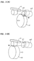
- Figs. 1A and 1B indicate the flow of torque. Further, Figs. 2A and 3A indicate the operating state of the planetary gear mechanism in the high position, and Figs. 2B and 3B indicate the operating state of the planetary gear mechanism in the low position.
- the reduction gear ratio in the high position is 1.
- the driving gear 6 can be engaged with the first output shaft 2 relative to the direction of rotation by the sleeve 5, whereby the first and second output shafts 2, 9 can be directly interconnected even when the transfer is in the high position.
- a torque transmitted from the transmission is transmitted to "OUTPUT 1", namely to the first output shaft 2, via the input shaft 1, ring gear r1, first pinion p1 and carrier c1, and to "OUTPUT 2", namely to the second output shaft 9, via the input shaft 1, ring gear r1, first pinion p1, carrier c1, first output shaft 2, sleeve 5, driving gear 6, chain 8 and driven gear 7.
- the reduction gear ratio in the low position is 1 + Zs/Zr, where Zs represents the number of teeth of sun gear s1 and Zr the number of teeth of ring gear r1.
- Fig. 4 is a diagram illustrating the ideal shape of meshing portions of the first and second pinions p1, p2 and of the sun gear s1.
- the first and second pinions p1, p2 mesh selectively with the sun gear s1 at a meshing portion M when the sun gear s1 is shifted.
- the meshing portion M of these pinions and the meshing portion M of the sun gear s1 which meshes with either of these pinions preferably are beveled so as to be composed of a plurality of conical surfaces that converge toward the distal end, as shown in Fig. 4.
- Fig. 5 is a gear train diagram showing the principal components of a transfer according to the second embodiment of the present invention.
- the second pinion p2 has an axial length greater than that of the first pinion p1 and has teeth at both axial ends thereof that are spaced apart from each other in the axial direction.
- the second end of the second pinion p2 is capable of being meshed with the sun gear s1, and the first end of the second pinion p2 extends toward the left side in Fig. 5 (i.e., toward the side of the main transmission) .
- the first pinion p1 and the first end of the second pinion p2 are in mesh at all times on the side of the main transmission.
- the present invention is advantageous in that is provides a transfer of a simplified structure, light weight and low cost.
Landscapes
- Engineering & Computer Science (AREA)
- Chemical & Material Sciences (AREA)
- Combustion & Propulsion (AREA)
- Transportation (AREA)
- Mechanical Engineering (AREA)
- Arrangement And Driving Of Transmission Devices (AREA)
- Structure Of Transmissions (AREA)
Claims (10)
- Boíte-transfert pour véhicule à quatre roues motrices, comprenant :un arbre d'entrée (1) ;un premier arbre de sortie (2) disposé coaxialement par rapport audit arbre d'entrée (1) ;une couronne de différentiel (r1) qui tourne conjointement avec ledit arbre d'entrée (1) ;un premier pignon (p1) en prise avec ladite couronne de différentiel (r1) ;un second pignon (p2) en prise avec ledit premier pignon (p1) à tout moment ;un support (c1), qui tourne conjointement avec ledit premier arbre de sortie (2), pour axialement supporter lesdits premier et second pignons (p1, p2) ;un pignon central (s1), qui est décalé axialement sur ledit premier arbre de sortie (2), pour venir sélectivement en prise avec ledit premier pignon (p1) ou ledit second pignon (p2) ;des moyens de verrouillage/déverrouillage (4) pour verrouiller ledit pignon central (s1) contre un mouvement ; etun second arbre de sortie (9), qui est disposé en parallèle avec ledit premier arbre de sortie (2), pour sélectivement transférer le couple dudit premier arbre de sortie (2) ou dudit pignon central (s1).
- Boíte-transfert selon la revendication 1, comprenant en outre une roue dentée d'entraínement (6) disposée de manière rotative en union avec ou par rapport audit premier arbre de sortie (2), et des moyens de synchronisation (6a) pour amener ladite roue d'entraínement (6) à tourner conjointement avec ledit pignon central (s1) ou ledit premier arbre de sortie (2).
- Boíte-transfert selon la revendication 1, comprenant en outre une roue dentée d'entraínement (6) pour venir en prise avec la seconde extrémité dudit pignon central (s1) lorsque la première extrémité dudit pignon central (s1) est à une position dans laquelle elle vient en prise avec ledit second pignon (p2) ;
un manchon (5) monté sur ledit premier arbre de sortie (2) afin de pouvoir venir en prise avec ledit premier arbre de sortie (2) dans une direction de rotation et de pouvoir être décalé le long dudit premier arbre de sortie (2) axialement par rapport à celui-ci, ledit manchon (5) pouvant être décalé afin que ladite roue d'entraínement (6) puisse venir en prise avec ledit premier arbre de sortie (2) dans la direction de rotation ;
un roue dentée (7), qui est prévue sur ledit second arbre de sortie (9) afin de tourner conjointement avec celui-ci, pour avoir la puissance transmise à celui-ci à partir de ladite roue d'entraínement (6). - Boíte-transfert selon la revendication 3, dans laquelle lorsque ladite boíte-transfert est dans une position haute, ledit pignon central (s1) vient en prise avec ledit second pignon (p2) et ladite roue d'entraínement (6), le couple étant transmis à ladite roue d'entraínement (6) via ledit pignon central (s1), puis audit second arbre de sortie (9) ; et
lorsque ladite boíte-transfert est dans une position basse, ledit pignon central (s1) vient en prise avec ledit premier pignon (p1) et est fixé par ledit frein, et ladite roue d'entraínement (6) vient en prise avec ledit premier arbre de sortie (2) dans la direction de rotation, le couple étant transmis à ladite roue d'entraínement (6) via ledit premier arbre de sortie (2), puis audit second arbre de sortie (9). - Boíte-transfert selon la revendication 4, dans laquelle lorsque la boíte-transfert est dans la position haute, ladite roue d'entraínement (6) vient en prise avec ledit premier arbre de sortie (2) dans la direction de rotation, lesdits premier et second arbres de sortie (2, 9) pouvant être placés dans un état directement connecté.
- Boíte-transfert selon la revendication 1, comprenant en outre une roue dentée d'entraínement (6) disposée sur ledit premier arbre de sortie (2) de manière rotative en union avec ou par rapport audit premier arbre de sortie (2), ledit arbre d'entraínement transmettant le couple audit second arbre de sortie (9) ; et
des moyens de synchronisation (6a) pour amener ladite roue d'entraínement (6) à tourner conjointement avec ledit pignon central (s1) ou ledit premier arbre de sortie (2). - Boíte-transfert selon l'une quelconque des revendications 1 à 6, dans laquelle ledit premier pignon (p1) s'étend axialement pour fournir des dents d'engrenage dans une mesure où il permet aux dents d'engrenage de venir en prise avec ledit pignon central (s1) et ledit second pignon (p2).
- Boíte-transfert selon l'une quelconque des revendications 1 à 6, dans laquelle ledit second pignon (p2) s'étend axialement pour fournir des dents d'engrenage dans une mesure où il permet aux dents d'engrenage de venir en prise avec ledit pignon central (s1) et ledit premier pignon (p1).
- Boíte-transfert selon la revendication 1 ou 2, dans laquelle lesdits moyens de verrouillage/déverrouillage (4) verrouillent ledit pignon central (s1) lorsque ledit pignon central (s1) vient en prise avec le premier pignon (p1) et n'est plus en prise avec le second pignon (p2).
- Boíte-transfert selon la revendication 2, dans laquelle lesdits moyens de synchronisation (6a) amènent ladite roue d'entraínement (6) à tourner conjointement avec ledit premier arbre de sortie (2) lorsque ledit pignon central (s1) vient en prise avec le premier pignon (p1), et amènent ladite roue d'entraínement (6) à tourner conjointement avec ledit pignon central (s1) lorsque ledit pignon central (s1) vient en prise avec le second pignon (p2).
Applications Claiming Priority (4)
| Application Number | Priority Date | Filing Date | Title |
|---|---|---|---|
| JP2000058709 | 2000-03-03 | ||
| JP2000058709 | 2000-03-03 | ||
| JP2001049586 | 2001-02-26 | ||
| JP2001049586A JP4673490B2 (ja) | 2000-03-03 | 2001-02-26 | 四輪駆動車用トランスファ装置 |
Publications (3)
| Publication Number | Publication Date |
|---|---|
| EP1129883A2 EP1129883A2 (fr) | 2001-09-05 |
| EP1129883A3 EP1129883A3 (fr) | 2003-06-18 |
| EP1129883B1 true EP1129883B1 (fr) | 2005-07-20 |
Family
ID=26586728
Family Applications (1)
| Application Number | Title | Priority Date | Filing Date |
|---|---|---|---|
| EP01105036A Expired - Lifetime EP1129883B1 (fr) | 2000-03-03 | 2001-03-01 | Boíte-transfert pour véhicule à quatre roues motrices |
Country Status (4)
| Country | Link |
|---|---|
| US (1) | US6485390B2 (fr) |
| EP (1) | EP1129883B1 (fr) |
| JP (1) | JP4673490B2 (fr) |
| DE (1) | DE60111975T2 (fr) |
Cited By (1)
| Publication number | Priority date | Publication date | Assignee | Title |
|---|---|---|---|---|
| US8905888B2 (en) | 2011-06-14 | 2014-12-09 | Toyota Jidosha Kabushiki Kaisha | Transfer mechanism for four-wheel drive vehicle |
Families Citing this family (12)
| Publication number | Priority date | Publication date | Assignee | Title |
|---|---|---|---|---|
| US6572506B2 (en) * | 2001-10-17 | 2003-06-03 | New Venture Gear, Inc. | Two-speed full-time transfer case with integrated planetary gearset and synchronized range shift |
| EP1869343B1 (fr) * | 2005-04-01 | 2014-08-06 | Tomactech A/S | Engrenage planetaire |
| US7534188B2 (en) * | 2006-01-27 | 2009-05-19 | Borgwarner Inc. | Transfer case input shaft brake system |
| JP5204098B2 (ja) * | 2006-04-30 | 2013-06-05 | トマクテック・アクティーゼルスカブ | 変速機 |
| US7780567B2 (en) * | 2007-06-07 | 2010-08-24 | Gm Global Technology Operations, Inc. | Input brake assembly |
| CN102016362B (zh) * | 2008-05-16 | 2013-12-04 | 博格华纳公司 | 使用链条和行星齿轮组作为最终传动器的手动变速器 |
| DE102011086061A1 (de) * | 2011-11-10 | 2013-05-16 | Zf Friedrichshafen Ag | Verteilergetriebe |
| CN102705455A (zh) * | 2012-05-18 | 2012-10-03 | 山耐斯气动液压(磐安)有限公司 | 一种电磁离合变速器 |
| CN106763561A (zh) * | 2016-12-17 | 2017-05-31 | 北奔重型汽车集团有限公司 | 一种重型汽车分动箱的换挡机构 |
| DE102020101918A1 (de) | 2020-01-28 | 2021-07-29 | Schaeffler Technologies AG & Co. KG | Getriebe für einen Elektroantrieb eines Kraftfahrzeuges |
| CN113815580A (zh) * | 2021-10-22 | 2021-12-21 | 梁清明 | 一种基于新能源的电动代步车用电机制动减速设备 |
| CN115325113B (zh) * | 2022-06-27 | 2025-04-01 | 中国第一汽车股份有限公司 | 一种用于车辆的分动器以及车辆 |
Family Cites Families (18)
| Publication number | Priority date | Publication date | Assignee | Title |
|---|---|---|---|---|
| DE3345322C1 (de) * | 1983-12-15 | 1985-05-15 | Getrag Getriebe- Und Zahnradfabrik Gmbh, 7140 Ludwigsburg | Getriebeanordnung |
| JPH0765660B2 (ja) * | 1986-04-10 | 1995-07-19 | トヨタ自動車株式会社 | 車両用動力分配装置 |
| US4846016A (en) * | 1986-07-31 | 1989-07-11 | Aisin Seiki Kabushiki Kaisha | Direct-coupling/differential changeover transfer apparatus |
| US4898259A (en) * | 1987-03-31 | 1990-02-06 | Aisin Seiki Kabushiki Kaisha | Four-wheel drive apparatus for automotive vehicles |
| JPH01293228A (ja) * | 1988-05-18 | 1989-11-27 | Toyota Motor Corp | 自動車用駆動トルク配分装置 |
| JPH02109730U (fr) * | 1989-02-21 | 1990-09-03 | ||
| JP3565566B2 (ja) * | 1991-03-28 | 2004-09-15 | 三菱自動車工業株式会社 | 4輪駆動車用駆動力配分装置 |
| US5226860A (en) * | 1991-12-31 | 1993-07-13 | Dana Corporation | Vehicle torque transfer case |
| CA2156187A1 (fr) * | 1993-12-16 | 1995-06-22 | Karou Sawase | Systeme de transfert |
| JP3655955B2 (ja) * | 1995-11-07 | 2005-06-02 | アイシン・エーアイ株式会社 | 自動車用トランスファ装置 |
| US5651749A (en) * | 1996-02-13 | 1997-07-29 | New Venture Gear, Inc. | Full-time transfer case with synchronized dual planetary gear reduction unit |
| US5884526A (en) * | 1996-09-27 | 1999-03-23 | Warn Industries, Inc. | Actuator for transfer case |
| US5967930A (en) * | 1997-05-08 | 1999-10-19 | New Venture Gear, Inc. | Adapter for transfer cases |
| AT405157B (de) * | 1997-07-01 | 1999-06-25 | Steyr Daimler Puch Ag | Zweistufiges verteilergetriebe für ein kraftfahrzeug |
| US5947858A (en) * | 1997-12-15 | 1999-09-07 | New Venture Gear, Inc. | Full-time transfer case with integrated planetary gear assembly and synchronized range shift mechanism |
| US6053072A (en) * | 1998-01-12 | 2000-04-25 | New Venture Gear, Inc. | Modular housing for vehicular power transfer devices |
| US6283887B1 (en) * | 1999-03-09 | 2001-09-04 | New Venture Gear, Inc. | Transfer case with synchronized range shift and adaptive clutch control |
| KR100346423B1 (ko) * | 1999-11-22 | 2002-08-01 | 현대자동차주식회사 | 4륜 구동 차량의 변속장치 |
-
2001
- 2001-02-26 JP JP2001049586A patent/JP4673490B2/ja not_active Expired - Fee Related
- 2001-03-01 DE DE60111975T patent/DE60111975T2/de not_active Expired - Lifetime
- 2001-03-01 EP EP01105036A patent/EP1129883B1/fr not_active Expired - Lifetime
- 2001-03-02 US US09/796,558 patent/US6485390B2/en not_active Expired - Lifetime
Cited By (1)
| Publication number | Priority date | Publication date | Assignee | Title |
|---|---|---|---|---|
| US8905888B2 (en) | 2011-06-14 | 2014-12-09 | Toyota Jidosha Kabushiki Kaisha | Transfer mechanism for four-wheel drive vehicle |
Also Published As
| Publication number | Publication date |
|---|---|
| US20010019981A1 (en) | 2001-09-06 |
| JP2001315543A (ja) | 2001-11-13 |
| DE60111975T2 (de) | 2006-05-24 |
| JP4673490B2 (ja) | 2011-04-20 |
| US6485390B2 (en) | 2002-11-26 |
| DE60111975D1 (de) | 2005-08-25 |
| EP1129883A2 (fr) | 2001-09-05 |
| EP1129883A3 (fr) | 2003-06-18 |
Similar Documents
| Publication | Publication Date | Title |
|---|---|---|
| US4624154A (en) | Drive unit for motor vehicle | |
| CN218777398U (zh) | 三挡电驱桥结构 | |
| JP2596931B2 (ja) | 4輪駆動車の動力伝達装置 | |
| EP1129883B1 (fr) | Boíte-transfert pour véhicule à quatre roues motrices | |
| JPS6157210B2 (fr) | ||
| KR100397570B1 (ko) | 차량용 동력전달장치 | |
| CN114161878A (zh) | 双电机外置式电驱动桥结构 | |
| US4907473A (en) | Differential mechanism of a four-wheel driving apparatus for vehicles | |
| EP1867515A1 (fr) | Entraînement d'axe ayant une double réduction planétaire | |
| CN111828565A (zh) | 变速机构和电桥驱动系统 | |
| US4805485A (en) | Power transfer device for four-wheel drive vehicles | |
| JPS629455B2 (fr) | ||
| CN116464745A (zh) | 机动车变速器、特别是电动车辆变速器 | |
| US4774854A (en) | Power transfer device for four-wheel drive vehicles | |
| JPS6383449A (ja) | 自動車の自動変速装置 | |
| CA2272313A1 (fr) | Mecanisme de marche arriere dans des boites-ponts de traction avant | |
| EP0274169A1 (fr) | Transmission de puissance pour un véhicule à quatre roues motrices | |
| JP2629189B2 (ja) | 自動変速機用歯車変速装置 | |
| JP3116630B2 (ja) | 自動変速機用歯車変速装置 | |
| CN115675041B (zh) | 具有三个前进挡的电驱桥传动结构 | |
| JP2558235B2 (ja) | 4輪駆動車の動力伝達装置 | |
| JPS6383450A (ja) | 横置式自動変速機 | |
| JP2002321541A (ja) | フルタイム四輪駆動車用トランスファ装置 | |
| JPS63242731A (ja) | フルタイム四輪駆動装置 | |
| JPS6338036A (ja) | トランスフア直結・差動切替装置 |
Legal Events
| Date | Code | Title | Description |
|---|---|---|---|
| PUAI | Public reference made under article 153(3) epc to a published international application that has entered the european phase |
Free format text: ORIGINAL CODE: 0009012 |
|
| AK | Designated contracting states |
Kind code of ref document: A2 Designated state(s): AT BE CH CY DE DK ES FI FR GB GR IE IT LI LU MC NL PT SE TR |
|
| AX | Request for extension of the european patent |
Free format text: AL;LT;LV;MK;RO;SI |
|
| PUAL | Search report despatched |
Free format text: ORIGINAL CODE: 0009013 |
|
| AK | Designated contracting states |
Designated state(s): AT BE CH CY DE DK ES FI FR GB GR IE IT LI LU MC NL PT SE TR |
|
| AX | Request for extension of the european patent |
Extension state: AL LT LV MK RO SI |
|
| 17P | Request for examination filed |
Effective date: 20030822 |
|
| AKX | Designation fees paid |
Designated state(s): DE FR GB |
|
| 17Q | First examination report despatched |
Effective date: 20040728 |
|
| GRAP | Despatch of communication of intention to grant a patent |
Free format text: ORIGINAL CODE: EPIDOSNIGR1 |
|
| GRAS | Grant fee paid |
Free format text: ORIGINAL CODE: EPIDOSNIGR3 |
|
| GRAA | (expected) grant |
Free format text: ORIGINAL CODE: 0009210 |
|
| AK | Designated contracting states |
Kind code of ref document: B1 Designated state(s): DE FR GB |
|
| REG | Reference to a national code |
Ref country code: GB Ref legal event code: FG4D |
|
| REF | Corresponds to: |
Ref document number: 60111975 Country of ref document: DE Date of ref document: 20050825 Kind code of ref document: P |
|
| ET | Fr: translation filed | ||
| PLBE | No opposition filed within time limit |
Free format text: ORIGINAL CODE: 0009261 |
|
| STAA | Information on the status of an ep patent application or granted ep patent |
Free format text: STATUS: NO OPPOSITION FILED WITHIN TIME LIMIT |
|
| 26N | No opposition filed |
Effective date: 20060421 |
|
| REG | Reference to a national code |
Ref country code: FR Ref legal event code: PLFP Year of fee payment: 16 |
|
| PGFP | Annual fee paid to national office [announced via postgrant information from national office to epo] |
Ref country code: DE Payment date: 20160223 Year of fee payment: 16 |
|
| PGFP | Annual fee paid to national office [announced via postgrant information from national office to epo] |
Ref country code: GB Payment date: 20160224 Year of fee payment: 16 Ref country code: FR Payment date: 20160208 Year of fee payment: 16 |
|
| REG | Reference to a national code |
Ref country code: DE Ref legal event code: R119 Ref document number: 60111975 Country of ref document: DE |
|
| GBPC | Gb: european patent ceased through non-payment of renewal fee |
Effective date: 20170301 |
|
| REG | Reference to a national code |
Ref country code: FR Ref legal event code: ST Effective date: 20171130 |
|
| PG25 | Lapsed in a contracting state [announced via postgrant information from national office to epo] |
Ref country code: DE Free format text: LAPSE BECAUSE OF NON-PAYMENT OF DUE FEES Effective date: 20171003 Ref country code: FR Free format text: LAPSE BECAUSE OF NON-PAYMENT OF DUE FEES Effective date: 20170331 |
|
| PG25 | Lapsed in a contracting state [announced via postgrant information from national office to epo] |
Ref country code: GB Free format text: LAPSE BECAUSE OF NON-PAYMENT OF DUE FEES Effective date: 20170301 |