EP1129959A2 - Capuchon de fermeture - Google Patents
Capuchon de fermeture Download PDFInfo
- Publication number
- EP1129959A2 EP1129959A2 EP01103837A EP01103837A EP1129959A2 EP 1129959 A2 EP1129959 A2 EP 1129959A2 EP 01103837 A EP01103837 A EP 01103837A EP 01103837 A EP01103837 A EP 01103837A EP 1129959 A2 EP1129959 A2 EP 1129959A2
- Authority
- EP
- European Patent Office
- Prior art keywords
- cover
- closure cap
- cap according
- cap housing
- slide
- Prior art date
- Legal status (The legal status is an assumption and is not a legal conclusion. Google has not performed a legal analysis and makes no representation as to the accuracy of the status listed.)
- Withdrawn
Links
Images



Classifications
-
- B—PERFORMING OPERATIONS; TRANSPORTING
- B65—CONVEYING; PACKING; STORING; HANDLING THIN OR FILAMENTARY MATERIAL
- B65D—CONTAINERS FOR STORAGE OR TRANSPORT OF ARTICLES OR MATERIALS, e.g. BAGS, BARRELS, BOTTLES, BOXES, CANS, CARTONS, CRATES, DRUMS, JARS, TANKS, HOPPERS, FORWARDING CONTAINERS; ACCESSORIES, CLOSURES, OR FITTINGS THEREFOR; PACKAGING ELEMENTS; PACKAGES
- B65D47/00—Closures with filling and discharging, or with discharging, devices
- B65D47/04—Closures with discharging devices other than pumps
- B65D47/06—Closures with discharging devices other than pumps with pouring spouts or tubes; with discharge nozzles or passages
- B65D47/08—Closures with discharging devices other than pumps with pouring spouts or tubes; with discharge nozzles or passages having articulated or hinged closures
- B65D47/0804—Closures with discharging devices other than pumps with pouring spouts or tubes; with discharge nozzles or passages having articulated or hinged closures integrally formed with the base element provided with the spout or discharge passage
- B65D47/0833—Hinges without elastic bias
- B65D47/0838—Hinges without elastic bias located at an edge of the base element
Definitions
- Caps are already known.
- a well-known cap has a cap body with a through opening which can be closed by a lid, which is hinged to the cap body.
- the lid has a pin which, when the lid is closed Closes through opening of the closure cap.
- the lid is held in a closed position in that the Pin in the through opening of the closure body by a Frictional force is maintained.
- the invention has for its object a differently designed To create a cap.
- the object of the invention based on creating a cap, which is one-handed can be opened easily and structurally simple and is inexpensive to manufacture.
- a closure cap according to the invention has in particular Cap housing, a cover and an actuating part.
- the lid is movably arranged in relation to the cap housing, in particular in such a way that the lid on the cap housing is articulated.
- the articulated connection provided for this is especially designed as a film hinge, which has several Has kink points or axes of rotation.
- the actuator is opposite both the cap housing and the Movable lid.
- the invention is in particular a cap with a Cap housing and with a compared to this cap housing movably arranged cover provided.
- the cap housing has an outlet opening through which, in particular if the cap is on a container, such as a bottle or the like, is mounted, a fluid or the like from the Container can escape through the outlet opening.
- the lid has an area, such as a peg or the like, which in a closed position of the lid this outlet opening of the cap housing essentially covers. Possibly this area seals the outlet opening of the cap housing fluid-tight.
- the cap also has a holding device which in a closed position of the lid, that this cover compared to the cap housing essentially is held in a closed position.
- This holding force is directed in such a way that they have a possibly acting force which loads the lid towards an open position, counteracts.
- this holding device is different from the area of the lid which is in a closed position of the lid Cover outlet opening, so in particular from one on the lid arranged spigot, which for covering or sealing or Closing the outlet opening is used.
- the holding device is also different from the outlet opening of the cap housing.
- the holding force is essentially not due to the interaction a pin arranged on the cover with the outlet opening of the cap housing is generated or not only by this interaction is produced.
- the holding device is preferred on the lid and / or on the cap housing and / or on an optionally provided actuating part arranged.
- the holding device is designed as a snap lock, this snap lock preferably at least two Has snap elements, one on the lid and one is arranged on the actuating part.
- a cap with a Cap housing and one movable relative to this cap housing arranged lid and one opposite the cap housing movably arranged actuating part is provided.
- This The actuating part is optionally also opposite the cover arranged movably.
- the actuator can be opened and / or closing the lid can be actuated or loaded.
- the actuating part and / or the cover has at least an articulation device with several articulation axes.
- hinge axes are arranged essentially adjacent or spaced apart.
- a joint device with adjacent arranged joint axes is designed in particular in such a way that the hinge device made of a plastic material is produced, which has a profile.
- This profiling is preferably designed such that thick spots and thin spots perpendicular to the joint axes adjacent to each other are arranged.
- the thin spots have a smaller number Material thickness on than the thick spots.
- the thin spots are designed in such a way that an effective around these thin points Torque causes the adjacent thick spots to be relative swivel towards each other around the thin area.
- the actuating part preferably has at least one sliding part or at least one sled, which can be moved lengthways is arranged. This slide or this sliding part is particularly preferred when opening and / or closing the Cover moved or moved.
- the actuating part preferably has an area which is connected to the slide, in particular articulated.
- This area particularly preferably extends at an angle from the sled when the sled is substantially perpendicular to the Axis of the outlet opening of the cap housing is aligned.
- the actuating part preferably has a carriage this sled articulated second part and a to this second part articulated first part.
- the first part is preferably articulated to the cap housing.
- the joint point at which the first is particularly preferred Part is hinged to the cap housing in the axial direction seen the axis of the outlet opening of the cap housing, below arranged the outlet opening, said outlet opening preferably arranged in the upper region of the cap housing is.
- the second part is preferably in the form of an arc of a circle or in the form of a segment of a cylinder designed and protruding when the lid is closed, preferably laterally, from the cap housing.
- the actuating part has an area which corresponds to a can be loaded from the outside. This Area is in particular the second part or an area of the second part.
- the pressure force introduced from the outside causes under predetermined conditions that a closed lid is opened. This pressure force is particularly preferred the carriage move, in particular essentially longitudinal.
- the actuating part preferably has an area which with the cap lid closed or with the cap housing locked sled, angled from the sled extends.
- This area particularly preferably has the first and that second part on.
- the actuating part is preferably designed in one piece, wherein if necessary, the articulation points within the actuating part are provided.
- the cap housing is preferably designed in one piece.
- the cap housing and / or the actuating part are preferably and / or the lid is made in one piece, being particularly preferably between the lid and the cap housing or between the actuator and the cap housing a connection is generated via a joint.
- the actuating part, and in particular the Slide of the operating part a trough-shaped depression on.
- This trough-shaped depression is then particularly Facing the cap housing when the carriage is perpendicular to Axis of the outlet opening of the cap housing extends.
- the cap housing particularly preferably has a raised profile in which the outlet opening of the cap housing is provided and which is in the trough-shaped recess of the sled extends.
- the dimensions of the trough-shaped depression in the longitudinal direction which essentially corresponds to the direction of displacement of the carriage, in the width direction and larger in depth than the corresponding ones Dimensions of the profile increase of the cap housing.
- these differences are the Dimensions in particular designed such that the increase in profiling of the cap housing in the trough-shaped recess of the Can extend sled.
- these dimensional differences are designed such that the carriage can be moved relative to the housing, being in the trough-like Deepening of the slide increased the profile of the cap housing is recorded.
- the shape of the trough-like depression or the increase in profiling can basically be designed in any way. Especially preferably this profile increase or the trough-shaped depression substantially perpendicular to the Axis of the outlet opening aligned area, which is essentially flat, and two each on one bevels on different sides of this area.
- the actuating part, and in particular its Sled, a through opening.
- This through opening in particular has a larger cross-sectional area than that Outlet opening of the cap housing.
- the Carriage on a through opening and is such the exit opening arranged of the clutch housing that the through hole of the carriage and the outlet opening of the clutch housing adjacent to each other in the axial direction of the Exit opening are arranged.
- the actuating part, and in particular the Sled, pre-tensioned when assembled, in particular in a direction opposite to the direction in which the carriage is loaded to open the lid becomes.
- the present invention in particular to understand that the Carriage adjacent to the outlet opening in the axial direction is arranged to this outlet opening, and substantially extends perpendicular to the axial axis of the outlet opening.
- the outlet opening level and the carriage given an angle of +/- 5 ° or +/- 10 ° or +/- 20 ° or greater is.
- At least one stop particularly preferably limits the mobility of the actuating part.
- This stop will be particularly formed by a surface that is inclined under a Angle to the plane which is perpendicular to the longitudinal axis the outlet opening is directed and against which the second part, in particular the cylinder segment-like design second part, with a load, which is an opening of the lid is supposed to effect.
- the slide is preferably guided by a guide device, wherein this guide device has stops.
- This is particularly designed such that the carriage protrusions such as strips or the like, which is guided in slots become. Due to the slot length and possibly the arrangement and the design of the projections becomes the possible travel path of the sled fixed or at least co-determined.
- a preferred closure cap according to the invention has at least a locking and / or friction device.
- This locking and / or friction device causes a load of the lid, which this towards an open position loaded, a predetermined force is opposed.
- This predetermined force is in particular greater than the forces movement of the lid towards an open position are opposed if this locking and / or friction device not movable between the two towards each other arranged components acts, one of which is the lid.
- This locking and / or friction device is particularly preferred different from a pin arranged on the cover and the in the outlet opening arranged in the cap housing. Possibly however, in addition to this locking and / or friction device a frictional force in a closed position of the cover thereby causes a pin arranged on the cover in engages the outlet opening, which may be elastic designed cones and the possibly elastic designed Exit opening form a press fit, which is not only serves to close the outlet opening in a fluid-tight manner, but also to bring about a holding force on the lid.
- the locking and / or friction device preferably has at least two locking and / or friction elements, between which a force is transmitted which corresponds to the lid movement in the direction is opposed to an open position. Especially at least one of these locking and / or friction elements is preferred on the cover and at least one of these locking and / or Arranged friction elements on the actuating part, in particular on the slide of the operating part.
- The is preferred Sled so biased that it snaps towards one Position of the locking device, which between the Carriage and the lid is arranged, is loaded.
- the cap lid preferably acts in a closed manner Position so with the actuating part and / or the cap housing together that the outlet opening of the cap housing is sealed fluid-tight.
- pin extends into the outlet opening, namely such that this outlet opening is closed in a fluid-tight manner becomes.
- the pin and the outlet opening are particularly preferred designed so that the pin in the outlet opening a closed lid position closes the frictional forces between the outlet opening and the spigot, however, if possible be kept low.
- the actuating part is preferably such in the assembled state arranged that the carriage is substantially vertical extends to the longitudinal axis of the outlet opening, the Carriage substantially adjacent to this exit opening is arranged.
- the carriage can be particularly preferably move lengthways. Preferably in one any of these slide positions the lid towards a closed position can be folded so that the Carriage arranged between the lid and the cap housing is.
- a longitudinal displacement of the slide in a first direction that a closed lid is opened becomes.
- Closing the lid particularly preferably brings about that the carriage may be in one of these first directions opposite direction is shifted.
- actuation of the actuating part causes First open a closed lid so that a locking and / or friction device, which the lid in a closed Holds position, is solved.
- the lid designed so that the lid in a locked, closed Position with a bead behind one arranged on the sled Bead engages in such a way that the interaction this beads a pivoting movement of the lid towards one open position is opposed to a force.
- the Sled is preferably initially by the actuation load shifted such that these beads disengage, and the lid towards an open position of the lid is freely movable.
- One particularly preferably causes further displacement of the slide and / or a preload of the cover, that the cover then opens in the direction of an Position is moved.
- a surface preferably acts for this of the cover with a surface of the carriage and / or a Surface of the carriage with a surface of the cap housing such together that a force is exerted on the lid, which generates a torque on the lid.
- These areas are special designed inclined.
- One of the interacting ones is preferred Surfaces are inclined, or both are Sloping surfaces.
- the inclination can in particular be such be designed so that one or two wedges work together. Also other designs of these surfaces are preferred, such as round shaped surfaces or the like.
- a container which is a Has container opening, and a closure cap according to the invention.
- the invention is based on the preferred and exemplary embodiments not limited.
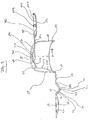
- Fig. 1 shows a closure cap 1 according to the invention with a Cap housing 10, a cover 12 and an actuating part 14.
- the actuator 14 is via a film hinge 16 to the Cap housing 10 hinged.
- the film hinge 16 is special designed such that the material thickness in the area of this Hinge is lower than in the adjacent areas, so that a certain mobility is made possible.
- the actuating part 14 has a first part 18, a second Part 20, and a third part 22 designed as a slide on.
- the first part 18 has an essentially flat surface 24 and is connected to the cap housing 10 via the film hinge 16 articulated.
- the second part 20 is connected via a thin point 26 the first part 18 articulated.
- the thin spot is essentially designed such that the material thickness in the area of the thin point is less than in the adjacent areas.
- the second part 20 of the actuating part 14 has a corrugation 28 with material elevations 30 and material depressions 32 on.
- This corrugation 28 is shown in Fig. 1 such that it is arranged on the underside of the second part 20.
- Prefers is, however, that this corrugation on the cover shown Top of the second part 20 is arranged, wherein this top is the side of the second part that is from that Cap housing 10 is facing away when the actuating part 14th or the carriage 22 is folded such that it between the Housing 10 and the cover 12 is arranged.
- the carriage 22 has a through opening 36 which is chamfered.
- This through opening 36 is lowered Area 38 arranged.
- On two opposite sides of this lowered area are two bevels 40, 42 arranged, which from the lowered area 38 with decreasing Run depth outwards.
- the lowered area 38 and the Slopes 40, 42 are on opposite sides of walls 44, 46 flanked. Perpendicular to these walls 44, 46 extend to the area facing away from the lowered area 38 Sides of the slopes 40, 42 walls 48, 50.
- the carriage 22 has locking or guide elements 53, 54 on which are designed here as rails.
- the cap housing has a substantially in the central area arranged reinforced area 56, which opposite the walls 58 of this cap housing is reinforced or which is more rigid than the walls 58.
- This reinforced The area faces the actuating part 14
- Area 60 has a slope 62 which is in the direction drops in which the actuator 14 to the cap housing 10 is articulated. This slope 62 serves as a stop for that second part 20 when the actuating part 14 on the cap housing 10 is folded and the second part is loaded.
- the Bevel 62 in particular causes that on the carriage 22 one certain bias acts when the actuator 14 on the Cap housing is folded. This preload causes in particular that the carriage 22 towards the end of the cap housing 10 is biased, on which the film hinge 16 between the cap housing 10 and the actuating part 14 are arranged is.
- the reinforced region 56 becomes parallel to the central axis 52 flanked by two walls 64, 66, each with one Slot, which is also parallel to the central axis 52 extends, are provided. This slot is from the top the wall covered. In this slot 68 and 72, the Snap locking elements 53, 54 into place so that these locking elements are longitudinally displaceable in the slot 68, 70. The interaction of these slots 68, 70 with the locking elements 53, 54 also causes the longitudinal displacement of the Carriage 22 is limited.
- the reinforced area 56 has a raised profile 72 with a central region 74 which is essentially is designed plan and perpendicular to the axis of this middle region provided bore 76 which extends a Exit opening 76 is.
- This outlet opening enables that a medium, such as fluid, can escape from a container, which provided with a closure cap according to the invention is.
- a container is in particular a shower gel plastic bottle or similar.
- the wall of bore 76 is slight compared to the substantially flat area 72 increased and preferably designed as a kind of pouring plug.
- the central region is 74 in the width and in the longitudinal direction and the slopes 78, 80 are designed to be smaller are as the lowered area 38 or the slopes 40, 42 of the Sled is or are so that the sled area with the bevels 40, 42 and the lowered area 38 in the folded State of the operating part 14 over the central area as well as the bevels 78, 80 of the profiling increase 72 can lay or can increase this profiling 72, the carriage in the axial direction or in the direction of central axis 52 can be moved.
- the lid 12 has a snap element 88, which is in the essentially on the side facing away from the film hinge 82 Cover extends perpendicular to the central axis 52.
- the Lid 12 also has slopes 90, 92, which from the lid bottom 94 protrude and, in the direction of the film hinge 82 seen from the lid bottom 94 obliquely or at an angle to Cover bottom 94 run, the distance between these slopes 90, 92 to the lid base 94 increases in the direction of the film hinge 82.
- Adjacent to these slopes 90, 92 is in the direction of Film hinge 82 each have an elevation 96, 98 which runs essentially parallel to the lid base.
- the lid has on its inside shown in Fig. 1 100 a stopper 102 which is in a closed Position of the cover in the outlet opening 76 of the cap housing 10 extends and closes it essentially fluid-tight.
- the dimensions of the bore 76 and the sealing pin 102 are especially designed so that they form a fit, which ensures tightness.
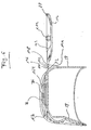
- Fig. 2 shows a sectional view along the line 2-2 Fig. 1.
- FIG. 2 particularly illustrates the slope 92 with the one following in the direction of the film hinge 82 Increase 98.
- Fig. 2 further illustrates how the middle area of the profiling elevation 72 of the cap housing 10 adjoin the slopes 78, 80. As can be seen from Fig. 2 , this middle region 74 is below the arranged upper housing wall 58.
- Fig. 2 also illustrates that the film hinge 16 facing slope 78 an essentially flat region 120 which is essentially parallel to the central area 74 is arranged.
- the sloping region 120 joins the descending direction Bevel 60, which opens into an area 122, which essentially in the direction of the longitudinal axis 124 of the Cap housing extends.
- This area 122 connects the Slope 60 with a slope 124, which is also sloping is designed.
- 2 is also the trough-like design of the slide 22 refer to. 2 shows that the second part of the control element 14 is designed like a cylinder segment and on the Outside corrugations 28 with material elevations 30 and material depressions 32 has.
- Fig. 3 shows a sectional view along the line 3-3 Fig. 1.
- Fig. 4 shows an isometric view of the 1 to 3 explained cap 1.
- Fig. 4 illustrates that the actuator 14 in the lower region 140 of the cap housing 10 and the lid 12 in the upper region is hinged to this cap housing.
- the actuating part 14 can in the direction of arrow 144 Articulation points 16, 26, 34 are pivoted so that the carriage essentially on or above the profile increase 72 of the cap housing 10 is arranged.
- the lid 12 can be folded, by moving around the film hinge axis in the direction of arrow 146 is pivoted so that the carriage 22 between the cap housing 10 or the increase in profiling 72 of the cap housing 10 and the lid 12 is arranged. Stretches in this position the nozzle 102 through the opening 36 of the carriage 22 in the opening 76 of the cap housing 10 and closes thus this outlet opening 76.
- Fig. 5 shows a closure cap 1 according to the invention which folds in the actuating part 14 and the cover 12 is closed.
- Fig. 5 further illustrates that the opening 36 in the carriage 22 is larger than the outlet opening 76 in the cap housing 10. This in particular enables the carriage 22 to be axially displaceable even when the cover 12 is closed.
- Fig. 5 further illustrates that the slope 92 is arranged adjacent to a slope 164 on the outside of the carriage 22, in particular in such a way that the slopes 164, 92 are arranged parallel to each other.
- Fig. 6 shows the closure cap of FIG. 5 with the open Cover 12.
- the cover 12 is based on that shown in Fig. 5 closed position is to be opened, the cylinder segment second part 20, especially in Direction of arrow 170, ie perpendicular to the longitudinal axis 125 of the Cap 1.
- This pressure load causes the sled displaced perpendicular to the longitudinal axis 125 of the cap housing 10 is, namely in the direction of the film hinge 82, which between the cap housing 10 and the lid 12 is arranged.
- This sliding movement of the carriage 22 is particularly due to this allows between the first part 18 and the second Part 20 a - preferably designed as a thin point 26 - Articulated connection is provided.
- the sliding movement is preferred further enabled by the fact that between the second Part 20 and the carriage 22, preferably as a film hinge 34 designed articulation is provided.
- the second Part is in particular like a cylinder segment or like an arc segment designed what the sliding movement of the slide 22nd assisted in the direction of arrow 170. It should be noted that instead of the aforementioned articulation points 26, 34 or the arcuate design of the second part 20 other coupling mechanisms are preferred which cause that a force, such as compressive force, in a sliding motion of the sledge is changed.
- the hinge point 82 between the cover 12 and the cap housing 10 is designed such that this articulation point 82 a bias on the lid 12 in a closed position of the Lid causes.
- the hinge point 82 is preferred for this purpose profiled designed, in particular it is provided that a plurality of hinge axes within this hinge point 82 are provided, which are arranged parallel to each other. It are in particular several kinks within the joint 82 provided. This is preferably designed in such a way that the joint has a tooth profile, which is such is designed so that several teeth in when the joint is open are arranged side by side in a linear direction, in such a way that that the facing tooth flanks of adjacent teeth are aligned at an angle to each other.
- the thin spots are designed such that each of these thin spots causes a folding by a predetermined angle, whereby this angle of all thin points to the entire folding angle of the lid.
- a predetermined angle For example, there are three thin places provided, each of which allows folding by 60 °, so that the lid can be folded essentially 180 °, without the film hinge 82 being overloaded or raised Material fatigue is exposed.
- the pretension of the articulation point 82 supports the opening of the Lid and in particular causes the lid to open further, as soon as the bevels 96, 98 of the lid 12 no longer apply abut the slopes 164 of the actuating part in parallel.
- the second part 20 of the operating part is standing 14 with the lid 12 closed over that of the joint 82 facing away from the lid end 180.
- FIG. 6 also shows the elevations 190, 192 and the depressions 194, 196, 198 of the articulation point 82.
- All components of the closure cap are preferably made of plastic manufactured. All components of the are particularly preferred Cap 1 injection molded parts.
Landscapes
- Engineering & Computer Science (AREA)
- Mechanical Engineering (AREA)
- Closures For Containers (AREA)
Applications Claiming Priority (2)
| Application Number | Priority Date | Filing Date | Title |
|---|---|---|---|
| DE2000109513 DE10009513A1 (de) | 2000-02-29 | 2000-02-29 | Verschlußkappe |
| DE10009513 | 2000-02-29 |
Publications (2)
| Publication Number | Publication Date |
|---|---|
| EP1129959A2 true EP1129959A2 (fr) | 2001-09-05 |
| EP1129959A3 EP1129959A3 (fr) | 2003-07-02 |
Family
ID=7632816
Family Applications (1)
| Application Number | Title | Priority Date | Filing Date |
|---|---|---|---|
| EP01103837A Withdrawn EP1129959A3 (fr) | 2000-02-29 | 2001-02-16 | Capuchon de fermeture |
Country Status (2)
| Country | Link |
|---|---|
| EP (1) | EP1129959A3 (fr) |
| DE (1) | DE10009513A1 (fr) |
Cited By (4)
| Publication number | Priority date | Publication date | Assignee | Title |
|---|---|---|---|---|
| EP1619134A1 (fr) | 2004-07-20 | 2006-01-25 | The Zebra Company | Bouchon à usage unique |
| FR2873354A1 (fr) * | 2004-07-20 | 2006-01-27 | Zebra Company Sa | Bouchon a usage unique |
| US7712618B2 (en) | 2004-07-20 | 2010-05-11 | The Zebra Company | Container cap with locking/unlocking mechanism that propels lid to open position |
| ES2577155A1 (es) * | 2015-01-13 | 2016-07-13 | Payper, S.A. | Dispositivo y procedimiento de alimentación de sacos a una máquina de llenado |
Family Cites Families (3)
| Publication number | Priority date | Publication date | Assignee | Title |
|---|---|---|---|---|
| FR2685294B1 (fr) * | 1991-12-19 | 1994-02-11 | Oreal | Capsule de distribution pour un produit fluide ou visqueux et recipient equipe d'une telle capsule. |
| US6253938B1 (en) * | 1998-09-25 | 2001-07-03 | Colgate-Palmolive Company | Indirectly activated closure |
| IL129856A (en) * | 1999-05-10 | 2002-02-10 | Albaad Massuot Yitzhak Ltd | Lid extended for packing |
-
2000
- 2000-02-29 DE DE2000109513 patent/DE10009513A1/de not_active Withdrawn
-
2001
- 2001-02-16 EP EP01103837A patent/EP1129959A3/fr not_active Withdrawn
Cited By (5)
| Publication number | Priority date | Publication date | Assignee | Title |
|---|---|---|---|---|
| EP1619134A1 (fr) | 2004-07-20 | 2006-01-25 | The Zebra Company | Bouchon à usage unique |
| FR2873354A1 (fr) * | 2004-07-20 | 2006-01-27 | Zebra Company Sa | Bouchon a usage unique |
| WO2006018493A1 (fr) * | 2004-07-20 | 2006-02-23 | The Zebra Company | Bouchon a usage unique |
| US7712618B2 (en) | 2004-07-20 | 2010-05-11 | The Zebra Company | Container cap with locking/unlocking mechanism that propels lid to open position |
| ES2577155A1 (es) * | 2015-01-13 | 2016-07-13 | Payper, S.A. | Dispositivo y procedimiento de alimentación de sacos a una máquina de llenado |
Also Published As
| Publication number | Publication date |
|---|---|
| DE10009513A1 (de) | 2001-08-30 |
| EP1129959A3 (fr) | 2003-07-02 |
Similar Documents
| Publication | Publication Date | Title |
|---|---|---|
| EP0999321B1 (fr) | Panneau de plancher | |
| EP2459815B1 (fr) | Revêtement composé de panneaux mécaniquement reliables entre eux | |
| EP2981737B1 (fr) | Chaîne de transport d'énergie | |
| DE9104509U1 (de) | Kniehebelverschlußvorrichtung | |
| EP1876048B1 (fr) | Baguette de protection de doigts, en particulier pour des portes basculant vers lýextérieur et lýintérieur | |
| EP0289981B1 (fr) | Manchon de câble en matière plastique à éléments élastiques d'étanchéité dans les domaines d'étanchéité | |
| DE602004000781T2 (de) | Durch zweimaliges Drücken betätigte Schliessvorrichtung | |
| WO2005012081A1 (fr) | Porte coulissante comprenant un cadre et une glissiere | |
| DE4213818A1 (de) | Teleskopische Positioniereinrichtung | |
| EP1129959A2 (fr) | Capuchon de fermeture | |
| CH689062A5 (de) | Befestigungskupplung fuer Wellrohre. | |
| EP1757838B1 (fr) | Chaîne rigide d'entraînement | |
| EP1963710B1 (fr) | Element de chaine dote d'un dispositif de verrouillage | |
| DE19948926B4 (de) | Kettenglied einer Energieführungskette | |
| EP0735220B1 (fr) | Serreure avec pêne réversible | |
| DE102006030769B3 (de) | Vorrichtung zur Aufnahme eines Kraftfahrzeug-Wagenhebers | |
| EP1818203A1 (fr) | Elément d'étanchéité pour une vitre | |
| EP1488885B1 (fr) | Tablier de protection, en particulier pour machines-outils | |
| DE10308592A1 (de) | Dichtung für die Führung eines öffnungsfähigen Fahrzeugdachs sowie Fahrzeugdach | |
| WO2022100983A1 (fr) | Cache de trou de serrure | |
| DE3416613C2 (de) | Feststellvorrichtung für Flügelfenster, Flügeltüren od.dgl. | |
| DE4413313C2 (de) | Leuchte | |
| DE19618912A1 (de) | Lamelle für ein Blatt eines vorzugsweise auf und ab bewegbaren Rollverschlusses für ein Tor, eine Tür, ein Fenster o. dgl. Öffnung | |
| DE19749457C2 (de) | Kohlehalteranordnung | |
| DE202019105247U1 (de) | Abdeckung für Kraftfahrzeugbauteil |
Legal Events
| Date | Code | Title | Description |
|---|---|---|---|
| PUAI | Public reference made under article 153(3) epc to a published international application that has entered the european phase |
Free format text: ORIGINAL CODE: 0009012 |
|
| AK | Designated contracting states |
Kind code of ref document: A2 Designated state(s): AT BE CH CY DE DK ES FI FR GB GR IE IT LI LU MC NL PT SE TR |
|
| AX | Request for extension of the european patent |
Free format text: AL;LT;LV;MK;RO;SI |
|
| PUAL | Search report despatched |
Free format text: ORIGINAL CODE: 0009013 |
|
| AK | Designated contracting states |
Designated state(s): AT BE CH CY DE DK ES FI FR GB GR IE IT LI LU MC NL PT SE TR |
|
| AX | Request for extension of the european patent |
Extension state: AL LT LV MK RO SI |
|
| STAA | Information on the status of an ep patent application or granted ep patent |
Free format text: STATUS: THE APPLICATION IS DEEMED TO BE WITHDRAWN |
|
| AKX | Designation fees paid |
Designated state(s): AT BE CH CY DE DK ES FI FR GB GR IE IT LI LU MC NL PT SE TR |
|
| 18D | Application deemed to be withdrawn |
Effective date: 20030829 |