EP1132573A2 - Machine à spirales pour fluides - Google Patents
Machine à spirales pour fluides Download PDFInfo
- Publication number
- EP1132573A2 EP1132573A2 EP01105612A EP01105612A EP1132573A2 EP 1132573 A2 EP1132573 A2 EP 1132573A2 EP 01105612 A EP01105612 A EP 01105612A EP 01105612 A EP01105612 A EP 01105612A EP 1132573 A2 EP1132573 A2 EP 1132573A2
- Authority
- EP
- European Patent Office
- Prior art keywords
- lap
- scroll
- seal
- outermost
- scrolls
- Prior art date
- Legal status (The legal status is an assumption and is not a legal conclusion. Google has not performed a legal analysis and makes no representation as to the accuracy of the status listed.)
- Granted
Links
- 239000012530 fluid Substances 0.000 title claims abstract description 83
- 239000000428 dust Substances 0.000 claims description 37
- 230000013011 mating Effects 0.000 claims description 14
- 238000007789 sealing Methods 0.000 claims description 12
- 238000007906 compression Methods 0.000 description 23
- 230000006835 compression Effects 0.000 description 19
- 230000007246 mechanism Effects 0.000 description 13
- 239000000470 constituent Substances 0.000 description 6
- 239000000463 material Substances 0.000 description 5
- 238000001816 cooling Methods 0.000 description 4
- 238000000034 method Methods 0.000 description 4
- 239000011347 resin Substances 0.000 description 4
- 229920005989 resin Polymers 0.000 description 4
- 229920000106 Liquid crystal polymer Polymers 0.000 description 2
- 239000004977 Liquid-crystal polymers (LCPs) Substances 0.000 description 2
- 239000004696 Poly ether ether ketone Substances 0.000 description 2
- 239000004734 Polyphenylene sulfide Substances 0.000 description 2
- 238000010276 construction Methods 0.000 description 2
- 230000007423 decrease Effects 0.000 description 2
- 238000007599 discharging Methods 0.000 description 2
- 230000010355 oscillation Effects 0.000 description 2
- 229920002530 polyetherether ketone Polymers 0.000 description 2
- 229920000069 polyphenylene sulfide Polymers 0.000 description 2
- 229920001343 polytetrafluoroethylene Polymers 0.000 description 2
- 239000004810 polytetrafluoroethylene Substances 0.000 description 2
- 238000003825 pressing Methods 0.000 description 2
- PXGOKWXKJXAPGV-UHFFFAOYSA-N Fluorine Chemical compound FF PXGOKWXKJXAPGV-UHFFFAOYSA-N 0.000 description 1
- 229910052782 aluminium Inorganic materials 0.000 description 1
- XAGFODPZIPBFFR-UHFFFAOYSA-N aluminium Chemical compound [Al] XAGFODPZIPBFFR-UHFFFAOYSA-N 0.000 description 1
- 238000010009 beating Methods 0.000 description 1
- JUPQTSLXMOCDHR-UHFFFAOYSA-N benzene-1,4-diol;bis(4-fluorophenyl)methanone Chemical compound OC1=CC=C(O)C=C1.C1=CC(F)=CC=C1C(=O)C1=CC=C(F)C=C1 JUPQTSLXMOCDHR-UHFFFAOYSA-N 0.000 description 1
- 230000008878 coupling Effects 0.000 description 1
- 238000010168 coupling process Methods 0.000 description 1
- 238000005859 coupling reaction Methods 0.000 description 1
- 239000013013 elastic material Substances 0.000 description 1
- 210000000887 face Anatomy 0.000 description 1
- 229910052731 fluorine Inorganic materials 0.000 description 1
- 239000011737 fluorine Substances 0.000 description 1
- 125000001153 fluoro group Chemical group F* 0.000 description 1
- 238000003754 machining Methods 0.000 description 1
- 229910052751 metal Inorganic materials 0.000 description 1
- 239000002184 metal Substances 0.000 description 1
- 150000002825 nitriles Chemical class 0.000 description 1
- 229920001296 polysiloxane Polymers 0.000 description 1
Images





Classifications
-
- F—MECHANICAL ENGINEERING; LIGHTING; HEATING; WEAPONS; BLASTING
- F04—POSITIVE - DISPLACEMENT MACHINES FOR LIQUIDS; PUMPS FOR LIQUIDS OR ELASTIC FLUIDS
- F04C—ROTARY-PISTON, OR OSCILLATING-PISTON, POSITIVE-DISPLACEMENT MACHINES FOR LIQUIDS; ROTARY-PISTON, OR OSCILLATING-PISTON, POSITIVE-DISPLACEMENT PUMPS
- F04C18/00—Rotary-piston pumps specially adapted for elastic fluids
- F04C18/02—Rotary-piston pumps specially adapted for elastic fluids of arcuate-engagement type, i.e. with circular translatory movement of co-operating members, each member having the same number of teeth or tooth-equivalents
- F04C18/0207—Rotary-piston pumps specially adapted for elastic fluids of arcuate-engagement type, i.e. with circular translatory movement of co-operating members, each member having the same number of teeth or tooth-equivalents both members having co-operating elements in spiral form
- F04C18/0215—Rotary-piston pumps specially adapted for elastic fluids of arcuate-engagement type, i.e. with circular translatory movement of co-operating members, each member having the same number of teeth or tooth-equivalents both members having co-operating elements in spiral form where only one member is moving
-
- F—MECHANICAL ENGINEERING; LIGHTING; HEATING; WEAPONS; BLASTING
- F04—POSITIVE - DISPLACEMENT MACHINES FOR LIQUIDS; PUMPS FOR LIQUIDS OR ELASTIC FLUIDS
- F04C—ROTARY-PISTON, OR OSCILLATING-PISTON, POSITIVE-DISPLACEMENT MACHINES FOR LIQUIDS; ROTARY-PISTON, OR OSCILLATING-PISTON, POSITIVE-DISPLACEMENT PUMPS
- F04C18/00—Rotary-piston pumps specially adapted for elastic fluids
- F04C18/02—Rotary-piston pumps specially adapted for elastic fluids of arcuate-engagement type, i.e. with circular translatory movement of co-operating members, each member having the same number of teeth or tooth-equivalents
- F04C18/0207—Rotary-piston pumps specially adapted for elastic fluids of arcuate-engagement type, i.e. with circular translatory movement of co-operating members, each member having the same number of teeth or tooth-equivalents both members having co-operating elements in spiral form
- F04C18/0246—Details concerning the involute wraps or their base, e.g. geometry
- F04C18/0269—Details concerning the involute wraps
- F04C18/0284—Details of the wrap tips
-
- F—MECHANICAL ENGINEERING; LIGHTING; HEATING; WEAPONS; BLASTING
- F04—POSITIVE - DISPLACEMENT MACHINES FOR LIQUIDS; PUMPS FOR LIQUIDS OR ELASTIC FLUIDS
- F04C—ROTARY-PISTON, OR OSCILLATING-PISTON, POSITIVE-DISPLACEMENT MACHINES FOR LIQUIDS; ROTARY-PISTON, OR OSCILLATING-PISTON, POSITIVE-DISPLACEMENT PUMPS
- F04C27/00—Sealing arrangements in rotary-piston pumps specially adapted for elastic fluids
- F04C27/005—Axial sealings for working fluid
Definitions
- the portion 121B of the mating face 121 is essentially not needed for taking in and compressing fluid.
- the mirror surface of the revolving scroll 107 is required to be extended over the portion 121B of the mating face 121, which leads to larger diameter of the revolving scroll.
- the width of the mating face 121 of the stationary scroll is enough as far as the annular groove 122 can be formed with narrow rims on both sides of the annular groove 122 remained.
- a still further object of the invention is to provide a scroll fluid machine capable of preventing the increase of load by friction when the achievement of high compression ratio is intended.
- the present invention is a scroll fluid machine having a stationary scroll and a revolving scroll characterized in that one of the scrolls, each scroll having a spiral scroll lap spiraling from the center side to the outer side, has an annular, outermost lap of which the radius is larger than that at the outer end of the spiral lap of the other scroll, the annular, outermost lap being the outermost wall; and the scrolls are assembled so that the lap of the other scroll is disposed in the inner side of the lap of the said one of the scrolls.
- the chip seal is shaped so that the thickness i.e., the dimension in the direction of the depth of the groove, becomes greater from the outer side toward the center side of the scroll.
- the chip seal As the pressure in an enclosed space formed toward the outer side of a lap is lower than that formed toward the inner side of the lap, the chip seal is pressed outward.
- the groove wall seal element between the chip seal and the outer side wall of the chip seal groove, even if a gap is developed between the groove wall and the side face of the chip seal in the higher pressure side, and between the lower face of the chip seal and the bottom face of the groove, the leak of the fluid is prevented by the groove wall seal element.
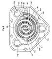
- FIG.8 illustrates a meshing state of a revolving scroll lap and stationary scroll lap.
- FIG.12 is an exploded view and a partial sectional view showing the construction of a scroll fluid machine of prior art.
- the stationary scroll 11 is, as shown in a plan view of FIG. 11, shaped like pentagon, an outlet port 16 for letting out the compressed fluid is provided on a land 11b located in the center part, inlet ports 11e and 11f are provided on lands 11j and 11k each located in the right and left of the outlet port 16.
- Three bosses llm are positioned in the same distance from the outlet port 16, where crank mechanisms are mounted to hinder the rotation of the revolving scroll to attain the revolving, or orbiting motion of the revolving scroll.
- a chip seal 34 having self-lubricating property is provided on the top face of the lap 11a.
- the chip seal 34 is preferable to be made of elastic resin material of superior anti-wear, anti-friction property, for example, fluorine group resin such as polytetrafluoroethylene(PTFE), or polyethersulfan(PES),polyphenylenesulfide(PPS), polyetheretherketone(PEEK), liquid crystal polymer(LCP), polyesphone(PSF), etc.
- fluorine group resin such as polytetrafluoroethylene(PTFE), or polyethersulfan(PES),polyphenylenesulfide(PPS), polyetheretherketone(PEEK), liquid crystal polymer(LCP), polyesphone(PSF), etc.
- the inlet port 11e and 11 f are opened in the sliding surface 11c.
- On the outer side of the stationary scroll are formed a lot of fins 23(FIG.11).
- a stationary scroll housing 13 Underside the stationary scroll 11 is screwed a stationary scroll housing 13 having the same outer shape as the stationary scroll in plan view. Inside the stationary scroll housing 13 is formed a room 13b which is communicated to the outside through openings 13f to allow the outside air to flow in and out.
- a motor housing 15 connecting to the stationary scroll housing 13 is formed under the housing 13 in which a motor not shown having a driving shaft 3 is mounted.
- the revolving scroll 12 In the room 13 of the stationary scroll housing, the revolving scroll 12 is supported via a bearing 5 for revolving motion on the eccentric pin of a driving shaft 4 fixed to the driving shaft 3.
- the revolving scroll 12 has a revolving scroll lap 12a standing erect on its sliding surface 12, the lap 12a meshing with the stationary scroll lap 11a.
- the revolving scroll 12 has three eyes 12g corresponding to the three eyes 11g provided in the bosses 11m of the stationary scroll 11, bearings 6 and 7 are fitted in the eye 12g, and the crank pin 21 is inserted in the inner races of these bearings. As the crank pin 21 is offset from the center of the crank journal 22 which is supported in the boss 11g of stationary scroll 11 via the bearings 8 and 9, the revolving scroll 12 revolves around the center of the driving shaft 3 as the driving shaft 3 rotates.
- Reference number 17 is the crank web of the crank.
- FIG.1 is a schematic plan view of a first embodiment of the revolving scroll according to the present invention.
- the revolving scroll 12A is formed like a pan having a bottom face 12c, the lap 12a being formed spirally extending toward the center from a point at the inner side of the outer wall 12b, 12b' of the pan-like shaped revolving scroll 12A.
- Three eyes 12i, 12j, and 12k for inserting the beatings 6, 7 of the crank pins 21 are provided at a span of 120 angle, the position of each eye corresponding to that of each eye 11g of the stationary scroll 11.
- a dust seal groove 18 from the end part 18d near the eye 12j to the end part 18d' near the eye 12i passing through on the wall 12b'.
- a chip seal groove 43 from the end part 43d near the center to the end part 43d' near the eye 12i passing through on the outer wall 12b.
- the chip seal groove 43 is formed, as shown in Section A-A, and B-B, so that the depth L1 at the outer side (Section A-A) is shallower than the depth L3 at the center side (Section B-B), that is, L1 ⁇ L3, and the groove 43 deepens gradually toward the center side.
- the chip seal 34 is accordingly formed so that its thickness L2 at the outer side (Section A-A) is smaller than that at the center side (Section B-B), that is, L2 ⁇ L4.
- the bottom 43b of the chip seal groove 43 may be the same in depth as the bottom 18b of the dust seal groove 18 is as shown in FIG.2(b) or the bottom 43b may be shallower than the bottom 18b as shown in FIG.2(a) or vice-versa.
- the chip seal 34 has, as shown in FIG.3(a) and FIG.3(b), projections 44 on the face 34c facing the bottom face 43b of the groove 43 formed by incising at a certain span so that the projections 44 have openings produced by the incision orienting toward the high pressure side 50, that is, toward the right direction in FIG.2.
- the width of the chip seal 34 is made smaller than that of the groove 43 for easing the assembling, and a groove 41 is machined on a face 34d of the chip seal 34.
- a cushion(seal element) 40 made of elastic resin such as silicone, fluorine, nitrile resin.
- the seal chip 34 is inserted in the groove 43 of the lap 12a with the cushion 40 fitted in the groove 41.
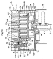
- the discharging fluid at the discharge port lid shown in FIG.10 pushes up the chip seal 34 from the lower face 34c to make the upper face 34a contact with the mating mirror face to form an enclosed space, when the pressure of the fluid is low, the enclosed space is difficult to be formed.
- the chip seal 34 is forced upward by the elastic force of the projection 44 to secure the forming of the enclosed space, and the leak of the fluid across the lap 12a is prevented.
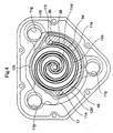
- FIG.4 shows a plan view of the combination of the stationary scroll lap 11a and revolving scroll lap 12a.
- the lap 11a of the stationary scroll 11 is disposed inside the lap 12a and outer wall 12b'.
- the fluid is taken into a taking-in space 45 formed between the stationary scroll lap 11a and the outer wall 12b' of the revolving scroll 12 from the inlet port 11e and 11f of the stationary scroll 11 as the pressure in the space 45 becomes negative and discharged from the discharge port lid of the stationary scroll 11, according as the revolving scroll 12 revolves.
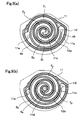
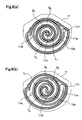
- FIG.5(a) the fluid in a space S1 communicating with the taking-in space 45 is enclosed in an enclosed space S2 (FIG.5(b)) formed by the revolving scroll lap 12a and the stationary scroll lap 11a owing to the oscillation of the revolving scroll. Then the volume of the enclosed space decreases in the order of S3(FIG.6(a)), S4(FIG.6(b)), S5(FIG.5(a)), S6(FIG.5(b)), S7(FIG.6(a)) to compress the fluid, and the compressed fluid is discharged from the discharge port lid when the last compression chamber S8 communicates with the discharge port lid as shown in FIG.6(b).
- the fluid in a space T1 communicating with the taking-in space 45 is enclosed in an enclosed space T2(FIG.5(b)) formed by the revolving scroll lap 12a and the stationary scroll lap 11a owing to the oscillation of the revolving scroll. Then the volume of the enclosed space decreases in the order of T3(FIG.6(a)), T4(FIG.6(b)), T5(FIG.5(a)), T6(FIG.5(b)), T7(FIG.6(a)) to compress the fluid, and the compressed fluid is discharged from the discharge port lid when the last compression chamber T8 communicates with the discharge port lid as shown in FIG.6(b).
- the chip seal groove 43 may be formed on the lap 12a from the end part 18d' to the end part 18d on the outer wall 12b".
- the chip seal 34 works also as dust seal.
- FIG.1 sealing of the outer wall is duplicated by a chip seal and dust seal in FIG.1, but in FIG.7 the duplicating parts do not exist.
- the same constituent element as that in FIG.1 is denoted with the same reference number.
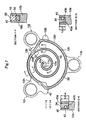
- the revolving scroll 12B is formed like a pan having the bottom face 12c, the lap 12a being formed spirally extending from a point at the inner side of the outer wall 12b, 12b' of the pan-like shaped revolving scroll 12B toward the center.
- Three eyes 12I, 12j, and 12k for inserting the crank pins 21 are provided at a span of 120° angle, the position of each eye corresponding to that of each eye 11g of the stationary scroll 11.
- a dust seal groove 18 As shown in Section F-F in FIG.7.
- a chip seal groove 43 On the lap 12a extending from the outer wall 12b, 12b' toward the center is, as shown in Section E-E, G-G, formed a chip seal groove 43 from the end part 43d near the center to the end part 43d' near the eye 12j.
- the chip seal groove 43 is formed, as shown in Section E-E, and G-G so that the depth L1 at the outer side is shallower than the depth L3 at the center side, that is, L1 ⁇ L3 and the groove 43 deepens gradually toward the center side.
- the chip seal 34 is accordingly formed so that its thickness L2 at the outer side is smaller than that at the center side, that is, L2 ⁇ L4.
- the bottom 43b of the chip seal groove 43 may be the same in depth as the bottom 18b of the dust seal groove 18 is as shown in FIG.2(b) or the bottom 43b may be shallower than the bottom 18b as shown in FIG.2(a) or vice-versa.
- the shape of the chip seal 36 is the same as detailed in FIG.3.
- the dust seal 34 is of the same material as that in FIG.1.
- the dust seal 34 may be of ring shape without a joint, or one or a plurality of adequate length may be inserted in the groove 18.
- FIG.8 shows a plan view of the combination of the stationary scroll lap 11a and revolving scroll lap 12a.
- the lap 11a of the stationary scroll 11 is disposed inside the lap 12a and outer wall 12b'.
- the fluid is taken into a taking-in space 45 formed between the stationary scroll lap 11a and the outer wall 12b' of the revolving scroll 12 from the inlet port 11e and 11f of the stationary scroll 11 as the pressure in the space 45 becomes negative and is discharged from the discharge port 11d of the stationary scroll 11, according as the revolving scroll 12 revolves.
- the chip seal groove 43 may be formed on the lap 12a extending from the end part 43d' to the outer wall 12b.
- the chip seal 34 works also as dust seal.
- FIG.9 shows another embodiments of a chip seal disposed in the chip seal groove.
- FIG.9(a) shows the case a columnar seal element 46A with circular section made of elastic material is used for the cushion(seal element)40 in FIG.3(a) of the chip seal 34 which is inserted in the chip seal groove 43
- FIG.9(b) shows the case a seal element of hollow octagon tube 46B is used.
- FIG.9(c) shows the case a chip seal 27 having rectangular section is used instead of the chip seal 34 having the seal element 46.
- the chip seal 27 has projections 28 on the face 27A facing the bottom face 43b of the groove 43 formed by incising at a certain span so that the projections 44 have openings produced by the incision orienting toward the high pressure side 50, the projections 44 exerting elastic force against the bottom face 43b, and also has on the higher pressure side face 27c projections 29 having elastic pushing force formed by incising the face 27c at a certain span so that the projections 44 have openings produced by incision orienting toward the high pressure side 50.
- the chip seal 27 is pushed up by the fluid pressure under the bottom face 27A and the upper face 27B contacts with the mating mirror face to form an enclosed space, when the fluid pressure is low, the enclosed space is difficult to be formed. In the embodiment, however, the chip seal 27 is forced upward by the elastic force of the projection 28 to secure the forming of the enclosed space, and the leak of the fluid across the lap 11a(12a) is prevented.
- the chip seal groove 43 shown in FIG.1 and FIG.7 is formed so that the depth L1 at the outer side is shallower than the depth L3 at the center side, that is, L1 ⁇ L3 and the groove 43 deepens gradually toward the center side, and the chip seal 34 is formed so that the thickness at the outer side L2 is smaller than the thickness L4 at the center side, that is, L2 ⁇ L4.
- L1 ⁇ L3 and L2 ⁇ L4 are permissible that L1 ⁇ L3 and L2 ⁇ L4.
- seal element As the thermal expansion of a seal element is different whether it is in higher pressure zone or lower pressure zone, it is also possible to divide the seal element into a plurality of seal elements having appropriate dimensions and dispose seal elements having different property in consideration of thermal expansion coefficient, anti-wear property, etc.
- either one of the stationary or revolving scroll each scroll having a spiral scroll lap spiraling from the center side to the outer side, is provided with an annular, outermost lap of which the radius is larger than that at the outer end of the spiral lap of the other scroll and the outermost lap forms the outermost wall of the said one of the scrolls, so the outermost wall has no excess width of rims as is the case with the prior art; and the said one and the other scrolls are assembled so that the lap of the said other scroll is disposed in the inner side of the lap of the said one of the scrolls. Therefore, the scroll mechanism becomes small sized, and the downsizing of the scroll fluid machine is achieved.
- the light weight of the constituent elements of the scroll fluid machine is achieved, the load for driving the scroll mechanism is lightened, and the power for driving the scroll fluid mechanism is reduced.
- the leakage of the compressed fluid between the compression chambers formed by the revolving scroll lap and the stationary scroll lap that is, the leakage from the chamber of higher pressure to that of lower pressure, is prevented, by providing seal elements between the top face of the laps of the stationary and revolving scrolls and mating sliding surfaces to keep gas-tight between chambers across the laps, and high compression ratio, or high pressure ratio can be achieved.
- the seal element for sliding surface sealing on the outermost lap achieves the role of sealing dust while at the same time achieving the sealing of fluid without providing an extra dust seal at still outside of the outermost lap.
- the light weight of the constituent elements of the scroll fluid machine is achieved, the load for driving the scroll mechanism is lightened, and the power for driving the scroll fluid mechanism is reduced.
Landscapes
- Engineering & Computer Science (AREA)
- Mechanical Engineering (AREA)
- General Engineering & Computer Science (AREA)
- Rotary Pumps (AREA)
Applications Claiming Priority (2)
| Application Number | Priority Date | Filing Date | Title |
|---|---|---|---|
| JP2000061262A JP3422747B2 (ja) | 2000-03-06 | 2000-03-06 | スクロール流体機械 |
| JP2000061262 | 2000-03-06 |
Publications (3)
| Publication Number | Publication Date |
|---|---|
| EP1132573A2 true EP1132573A2 (fr) | 2001-09-12 |
| EP1132573A3 EP1132573A3 (fr) | 2002-06-12 |
| EP1132573B1 EP1132573B1 (fr) | 2007-02-21 |
Family
ID=18581423
Family Applications (1)
| Application Number | Title | Priority Date | Filing Date |
|---|---|---|---|
| EP01105612A Expired - Lifetime EP1132573B1 (fr) | 2000-03-06 | 2001-03-06 | Machine à spirales pour fluides |
Country Status (4)
| Country | Link |
|---|---|
| US (1) | US6695597B2 (fr) |
| EP (1) | EP1132573B1 (fr) |
| JP (1) | JP3422747B2 (fr) |
| DE (1) | DE60126695T2 (fr) |
Cited By (5)
| Publication number | Priority date | Publication date | Assignee | Title |
|---|---|---|---|---|
| EP1643079A1 (fr) * | 2004-09-29 | 2006-04-05 | Anest Iwata Corporation | Volute à mouvement orbital d'une machine à volutes |
| EP1593850A3 (fr) * | 2004-05-07 | 2006-06-07 | Anest Iwata Corporation | Joint pour une machine à spirales |
| EP1837525A3 (fr) * | 2006-03-23 | 2010-06-09 | Anest Iwata Corporation | Machine à spirales |
| US10451068B2 (en) | 2014-11-07 | 2019-10-22 | Trane International Inc. | Tip seal |
| US20220034322A1 (en) * | 2018-11-01 | 2022-02-03 | Gree Green Refrigeration Technology Center Co., Ltd. Of Zhuhai | Sealing structure and scroll air compressor having same |
Families Citing this family (16)
| Publication number | Priority date | Publication date | Assignee | Title |
|---|---|---|---|---|
| US20040238344A1 (en) * | 2003-05-30 | 2004-12-02 | Benoit Jeffrey T. | Air purification system using excimer lamps for ultra-violet photocatalytic oxidation |
| JP2005307770A (ja) * | 2004-04-19 | 2005-11-04 | Anest Iwata Corp | スクロール流体機械 |
| JP4873706B2 (ja) * | 2006-09-27 | 2012-02-08 | アネスト岩田株式会社 | 流体機械のシール構造 |
| JP5352384B2 (ja) * | 2009-08-31 | 2013-11-27 | 株式会社日立産機システム | スクロール式流体機械 |
| US11047389B2 (en) | 2010-04-16 | 2021-06-29 | Air Squared, Inc. | Multi-stage scroll vacuum pumps and related scroll devices |
| US9228587B2 (en) | 2013-02-17 | 2016-01-05 | Yujin Machinery Ltd. | Scroll compressor for accommodating thermal expansion of dust seal |
| JP5817760B2 (ja) * | 2013-03-04 | 2015-11-18 | 株式会社豊田自動織機 | スクロール型圧縮機 |
| US10865793B2 (en) | 2016-12-06 | 2020-12-15 | Air Squared, Inc. | Scroll type device having liquid cooling through idler shafts |
| EP3788262B1 (fr) | 2018-05-04 | 2024-11-20 | Air Squared, Inc. | Refroidissement par liquide de compresseur, de détendeur ou de pompe à vide à volute fixe et orbitale |
| US11067080B2 (en) * | 2018-07-17 | 2021-07-20 | Air Squared, Inc. | Low cost scroll compressor or vacuum pump |
| US20200025199A1 (en) | 2018-07-17 | 2020-01-23 | Air Squared, Inc. | Dual drive co-rotating spinning scroll compressor or expander |
| US11530703B2 (en) | 2018-07-18 | 2022-12-20 | Air Squared, Inc. | Orbiting scroll device lubrication |
| US11473572B2 (en) | 2019-06-25 | 2022-10-18 | Air Squared, Inc. | Aftercooler for cooling compressed working fluid |
| US11898557B2 (en) | 2020-11-30 | 2024-02-13 | Air Squared, Inc. | Liquid cooling of a scroll type compressor with liquid supply through the crankshaft |
| US11885328B2 (en) | 2021-07-19 | 2024-01-30 | Air Squared, Inc. | Scroll device with an integrated cooling loop |
| EP4174285B1 (fr) | 2022-12-22 | 2024-10-23 | Pfeiffer Vacuum Technology AG | Pompe à vide à spirales |
Citations (1)
| Publication number | Priority date | Publication date | Assignee | Title |
|---|---|---|---|---|
| JPH07208353A (ja) | 1994-01-27 | 1995-08-08 | Sanyo Electric Co Ltd | スクロール型無給油式流体機械 |
Family Cites Families (15)
| Publication number | Priority date | Publication date | Assignee | Title |
|---|---|---|---|---|
| JPS58172404A (ja) * | 1982-04-05 | 1983-10-11 | Hitachi Ltd | スクロ−ル流体機械 |
| KR860001681Y1 (en) * | 1983-04-29 | 1986-07-25 | Mitsubishi Electric Corp | Scroll type compressor |
| JPS6098186A (ja) * | 1983-11-04 | 1985-06-01 | Sanden Corp | スクロ−ル型圧縮機 |
| DE3711986A1 (de) * | 1986-04-11 | 1987-10-15 | Hitachi Ltd | Kompressor in spiralbauweise und verfahren zu seiner herstellung |
| DE4200530A1 (de) * | 1991-01-19 | 1992-07-23 | Volkswagen Ag | Dichtungsanordnung in einer verdraengermaschine fuer kompressible medien |
| JPH0587065A (ja) * | 1991-09-30 | 1993-04-06 | Kubota Corp | スクロール圧縮機 |
| JPH06207588A (ja) * | 1992-11-20 | 1994-07-26 | Kobe Steel Ltd | スクロール圧縮機 |
| US5366358A (en) | 1993-01-27 | 1994-11-22 | Grenci Charles A | Oil free scroll vacuum pump |
| US5759020A (en) * | 1994-04-05 | 1998-06-02 | Air Squared, Inc. | Scroll compressor having tip seals and idler crank assemblies |
| US5466134A (en) * | 1994-04-05 | 1995-11-14 | Puritan Bennett Corporation | Scroll compressor having idler cranks and strengthening and heat dissipating ribs |
| JP3369786B2 (ja) * | 1995-04-19 | 2003-01-20 | サンデン株式会社 | スクロール型圧縮機 |
| JPH09184493A (ja) * | 1995-12-28 | 1997-07-15 | Anest Iwata Corp | スクロール流体機械 |
| JPH1162858A (ja) * | 1997-08-08 | 1999-03-05 | Toyota Autom Loom Works Ltd | スクロール型圧縮機のシール構造 |
| JPH1193864A (ja) * | 1997-09-16 | 1999-04-06 | Toyota Autom Loom Works Ltd | スクロール型流体機械 |
| US6224357B1 (en) * | 1998-09-29 | 2001-05-01 | Tokioco Ltd. | Scroll fluid machine having an orbiting radius varying mechanism and a clearance between the wrap portions |
-
2000
- 2000-03-06 JP JP2000061262A patent/JP3422747B2/ja not_active Expired - Fee Related
-
2001
- 2001-03-06 US US09/799,099 patent/US6695597B2/en not_active Expired - Lifetime
- 2001-03-06 DE DE60126695T patent/DE60126695T2/de not_active Expired - Lifetime
- 2001-03-06 EP EP01105612A patent/EP1132573B1/fr not_active Expired - Lifetime
Patent Citations (1)
| Publication number | Priority date | Publication date | Assignee | Title |
|---|---|---|---|---|
| JPH07208353A (ja) | 1994-01-27 | 1995-08-08 | Sanyo Electric Co Ltd | スクロール型無給油式流体機械 |
Cited By (6)
| Publication number | Priority date | Publication date | Assignee | Title |
|---|---|---|---|---|
| EP1593850A3 (fr) * | 2004-05-07 | 2006-06-07 | Anest Iwata Corporation | Joint pour une machine à spirales |
| EP1643079A1 (fr) * | 2004-09-29 | 2006-04-05 | Anest Iwata Corporation | Volute à mouvement orbital d'une machine à volutes |
| EP1837525A3 (fr) * | 2006-03-23 | 2010-06-09 | Anest Iwata Corporation | Machine à spirales |
| US10451068B2 (en) | 2014-11-07 | 2019-10-22 | Trane International Inc. | Tip seal |
| US20220034322A1 (en) * | 2018-11-01 | 2022-02-03 | Gree Green Refrigeration Technology Center Co., Ltd. Of Zhuhai | Sealing structure and scroll air compressor having same |
| US11725657B2 (en) * | 2018-11-01 | 2023-08-15 | Gree Green Refrigeration Technology Center Co., Ltd. Of Zhuhai | Sealing structure and scroll air compressor having same |
Also Published As
| Publication number | Publication date |
|---|---|
| JP3422747B2 (ja) | 2003-06-30 |
| DE60126695T2 (de) | 2007-12-06 |
| EP1132573B1 (fr) | 2007-02-21 |
| US6695597B2 (en) | 2004-02-24 |
| JP2001248576A (ja) | 2001-09-14 |
| DE60126695D1 (de) | 2007-04-05 |
| EP1132573A3 (fr) | 2002-06-12 |
| US20010038800A1 (en) | 2001-11-08 |
Similar Documents
| Publication | Publication Date | Title |
|---|---|---|
| EP1132573B1 (fr) | Machine à spirales pour fluides | |
| US4477238A (en) | Scroll type compressor with wrap portions of different axial heights | |
| US4303379A (en) | Scroll-type compressor with reduced housing radius | |
| EP0077214B1 (fr) | Compresseur à volutes imbriquées avec rendement élevé | |
| US6030192A (en) | Scroll compressor having bearing structure in the orbiting scroll to eliminate tipping forces | |
| US4304535A (en) | Scroll-type compressor units with minimum housing and scroll plate radii | |
| US6454551B2 (en) | Seal structure in a scroll type compressor | |
| US4437820A (en) | Scroll type fluid compressor unit with axial end surface sealing means | |
| US5931650A (en) | Hermetic electric scroll compressor having a lubricating passage in the orbiting scroll | |
| US6887058B2 (en) | Fluid machinery | |
| KR100434931B1 (ko) | 스크롤형유체변위장치 | |
| KR100875049B1 (ko) | 스크롤형 유체기계 | |
| EP0012614A1 (fr) | Améliorations à des compresseurs à fluide du type à volutes imbriquées | |
| EP0913580A1 (fr) | Machine à fluide du type à volutes | |
| US6544014B2 (en) | Scroll-type compressors | |
| JPH09250464A (ja) | スクロール型コンプレッサに用いる自転防止機構 | |
| US12473917B2 (en) | Scroll assemblies and compressors including the same | |
| JPH09250467A (ja) | スクロール式流体機械 | |
| JPH0763176A (ja) | スクロール式流体機械 | |
| JP2779814B2 (ja) | 容積形圧縮機 | |
| KR0173575B1 (ko) | 코로테이팅 스크롤형 유체기계 | |
| CN121925518A (zh) | 涡旋组件和包括该涡旋组件的压缩机 | |
| JPH03138477A (ja) | スクロール流体機械 | |
| JPH01121582A (ja) | スクロール圧縮機 | |
| JPH10205465A (ja) | スクロールコンプレッサ |
Legal Events
| Date | Code | Title | Description |
|---|---|---|---|
| PUAI | Public reference made under article 153(3) epc to a published international application that has entered the european phase |
Free format text: ORIGINAL CODE: 0009012 |
|
| AK | Designated contracting states |
Kind code of ref document: A2 Designated state(s): AT BE CH CY DE DK ES FI FR GB GR IE IT LI LU MC NL PT SE TR |
|
| AX | Request for extension of the european patent |
Free format text: AL;LT;LV;MK;RO;SI |
|
| PUAL | Search report despatched |
Free format text: ORIGINAL CODE: 0009013 |
|
| AK | Designated contracting states |
Kind code of ref document: A3 Designated state(s): AT BE CH CY DE DK ES FI FR GB GR IE IT LI LU MC NL PT SE TR |
|
| AX | Request for extension of the european patent |
Free format text: AL;LT;LV;MK;RO;SI |
|
| 17P | Request for examination filed |
Effective date: 20021209 |
|
| AKX | Designation fees paid |
Designated state(s): BE DE FR GB IT |
|
| GRAP | Despatch of communication of intention to grant a patent |
Free format text: ORIGINAL CODE: EPIDOSNIGR1 |
|
| GRAS | Grant fee paid |
Free format text: ORIGINAL CODE: EPIDOSNIGR3 |
|
| GRAA | (expected) grant |
Free format text: ORIGINAL CODE: 0009210 |
|
| AK | Designated contracting states |
Kind code of ref document: B1 Designated state(s): BE DE FR GB IT |
|
| REG | Reference to a national code |
Ref country code: GB Ref legal event code: FG4D |
|
| REF | Corresponds to: |
Ref document number: 60126695 Country of ref document: DE Date of ref document: 20070405 Kind code of ref document: P |
|
| ET | Fr: translation filed | ||
| PLBE | No opposition filed within time limit |
Free format text: ORIGINAL CODE: 0009261 |
|
| STAA | Information on the status of an ep patent application or granted ep patent |
Free format text: STATUS: NO OPPOSITION FILED WITHIN TIME LIMIT |
|
| 26N | No opposition filed |
Effective date: 20071122 |
|
| PGFP | Annual fee paid to national office [announced via postgrant information from national office to epo] |
Ref country code: GB Payment date: 20080320 Year of fee payment: 8 |
|
| PGFP | Annual fee paid to national office [announced via postgrant information from national office to epo] |
Ref country code: IT Payment date: 20080329 Year of fee payment: 8 |
|
| PGFP | Annual fee paid to national office [announced via postgrant information from national office to epo] |
Ref country code: FR Payment date: 20080327 Year of fee payment: 8 |
|
| GBPC | Gb: european patent ceased through non-payment of renewal fee |
Effective date: 20090306 |
|
| REG | Reference to a national code |
Ref country code: FR Ref legal event code: ST Effective date: 20091130 |
|
| PG25 | Lapsed in a contracting state [announced via postgrant information from national office to epo] |
Ref country code: GB Free format text: LAPSE BECAUSE OF NON-PAYMENT OF DUE FEES Effective date: 20090306 Ref country code: FR Free format text: LAPSE BECAUSE OF NON-PAYMENT OF DUE FEES Effective date: 20091123 |
|
| PG25 | Lapsed in a contracting state [announced via postgrant information from national office to epo] |
Ref country code: IT Free format text: LAPSE BECAUSE OF NON-PAYMENT OF DUE FEES Effective date: 20090306 |
|
| PGFP | Annual fee paid to national office [announced via postgrant information from national office to epo] |
Ref country code: DE Payment date: 20180322 Year of fee payment: 18 |
|
| PGFP | Annual fee paid to national office [announced via postgrant information from national office to epo] |
Ref country code: BE Payment date: 20180321 Year of fee payment: 18 |
|
| REG | Reference to a national code |
Ref country code: DE Ref legal event code: R119 Ref document number: 60126695 Country of ref document: DE |
|
| REG | Reference to a national code |
Ref country code: BE Ref legal event code: MM Effective date: 20190331 |
|
| PG25 | Lapsed in a contracting state [announced via postgrant information from national office to epo] |
Ref country code: DE Free format text: LAPSE BECAUSE OF NON-PAYMENT OF DUE FEES Effective date: 20191001 |
|
| PG25 | Lapsed in a contracting state [announced via postgrant information from national office to epo] |
Ref country code: BE Free format text: LAPSE BECAUSE OF NON-PAYMENT OF DUE FEES Effective date: 20190331 |