EP1132575A1 - Konfiguration von filmkühlungsbohrungen in gasturbinenschaufeln - Google Patents
Konfiguration von filmkühlungsbohrungen in gasturbinenschaufeln Download PDFInfo
- Publication number
- EP1132575A1 EP1132575A1 EP99943365A EP99943365A EP1132575A1 EP 1132575 A1 EP1132575 A1 EP 1132575A1 EP 99943365 A EP99943365 A EP 99943365A EP 99943365 A EP99943365 A EP 99943365A EP 1132575 A1 EP1132575 A1 EP 1132575A1
- Authority
- EP
- European Patent Office
- Prior art keywords
- cooling
- blade
- passage
- film
- turbulators
- Prior art date
- Legal status (The legal status is an assumption and is not a legal conclusion. Google has not performed a legal analysis and makes no representation as to the accuracy of the status listed.)
- Withdrawn
Links
Images


Classifications
-
- F—MECHANICAL ENGINEERING; LIGHTING; HEATING; WEAPONS; BLASTING
- F01—MACHINES OR ENGINES IN GENERAL; ENGINE PLANTS IN GENERAL; STEAM ENGINES
- F01D—NON-POSITIVE DISPLACEMENT MACHINES OR ENGINES, e.g. STEAM TURBINES
- F01D5/00—Blades; Blade-carrying members; Heating, heat-insulating, cooling or antivibration means on the blades or the members
- F01D5/12—Blades
- F01D5/14—Form or construction
- F01D5/18—Hollow blades, i.e. blades with cooling or heating channels or cavities; Heating, heat-insulating or cooling means on blades
- F01D5/187—Convection cooling
- F01D5/188—Convection cooling with an insert in the blade cavity to guide the cooling fluid, e.g. forming a separation wall
-
- F—MECHANICAL ENGINEERING; LIGHTING; HEATING; WEAPONS; BLASTING
- F05—INDEXING SCHEMES RELATING TO ENGINES OR PUMPS IN VARIOUS SUBCLASSES OF CLASSES F01-F04
- F05D—INDEXING SCHEME FOR ASPECTS RELATING TO NON-POSITIVE-DISPLACEMENT MACHINES OR ENGINES, GAS-TURBINES OR JET-PROPULSION PLANTS
- F05D2260/00—Function
- F05D2260/20—Heat transfer, e.g. cooling
- F05D2260/201—Heat transfer, e.g. cooling by impingement of a fluid
-
- F—MECHANICAL ENGINEERING; LIGHTING; HEATING; WEAPONS; BLASTING
- F05—INDEXING SCHEMES RELATING TO ENGINES OR PUMPS IN VARIOUS SUBCLASSES OF CLASSES F01-F04
- F05D—INDEXING SCHEME FOR ASPECTS RELATING TO NON-POSITIVE-DISPLACEMENT MACHINES OR ENGINES, GAS-TURBINES OR JET-PROPULSION PLANTS
- F05D2260/00—Function
- F05D2260/20—Heat transfer, e.g. cooling
- F05D2260/202—Heat transfer, e.g. cooling by film cooling
-
- F—MECHANICAL ENGINEERING; LIGHTING; HEATING; WEAPONS; BLASTING
- F05—INDEXING SCHEMES RELATING TO ENGINES OR PUMPS IN VARIOUS SUBCLASSES OF CLASSES F01-F04
- F05D—INDEXING SCHEME FOR ASPECTS RELATING TO NON-POSITIVE-DISPLACEMENT MACHINES OR ENGINES, GAS-TURBINES OR JET-PROPULSION PLANTS
- F05D2260/00—Function
- F05D2260/20—Heat transfer, e.g. cooling
- F05D2260/221—Improvement of heat transfer
- F05D2260/2214—Improvement of heat transfer by increasing the heat transfer surface
- F05D2260/22141—Improvement of heat transfer by increasing the heat transfer surface using fins or ribs
Definitions
- the present invention relates to a film cooling hole structure of a gas turbine moving blade in which arrangement of film cooling holes is optimized so as to enhance a cooling efficiency of the moving blade.
- cooling air is flown in a serpentine cooling passage provided in the blade for effecting a convection cooling and also cooling air is injected from film cooling holes onto a blade outer surface for effecting a film cooling.
- Fig. 6 is a cross sectional view of one example of a gas turbine moving blade cooling structure in the prior art, wherein Fig. 6(a) shows an entire portion of the cooling structure and Fig. 6(b) shows a cross sectional view taken on line B-B of Fig. 6(a).
- numeral 30 designates a moving blade, whose interior is sectioned by ribs 36, 37, 38, 39 to form a leading edge side cooling passage 31, a serpentine cooling passage comprising cooling passage portions 32, 33, 34 in a blade central portion and a trailing edge side cooling passage 35, said cooling passage portions 32, 33, 34 communicating with each other in this order.
- Cooling air 40 in a blade base portion enters the cooling passages, wherein the cooling air flowing in the leading edge side cooling passage 31 cools a blade leading edge portion and flows out of leading edge side holes as air 40a, the cooling air flowing in the cooling passage portions 32, 33, 34 cools the blade central portion and flows out of film cooling holes provided in a blade surface for effecting a film cooling of the blade surface as air 40b and the cooling air flowing in the trailing edge side cooling passage 35 cools a blade trailing edge portion and flows out of a blade tip portion as air 40c as well as flows out of a multiplicity of cooling holes provided in a blade trailing edge as air 40d.
- Fig. 5 is a cross sectional view of another example of a gas turbine moving blade cooling structure in the prior art, wherein Fig. 5(a) shows an entire portion of the cooling structure and Fig. 5(b) shows a cross sectional view taken on line A-A of Fig. 5(a).
- numeral 20 designates a moving blade, whose interior is sectioned to form a leading edge side cooling passage 21, a serpentine cooling passage comprising cooling passage portions 22, 23, 24 and a serpentine cooling passage comprising cooling passage portions 25, 26, 27 on a rear side thereof, said cooling passage portions 22, 23, 24 and those 25, 26, 27 communicating with each other in said orders, respectively.
- Cooling air 41 in a blade base portion enters the cooling passages, wherein the cooling air entering passage (A) flows into the leading edge side cooling passage 21 and flows out of leading edge side holes as air 41a, the cooling air entering passage (B) flows into the cooling passage portion 22 to then flow through the cooling passage portions 23, 24 and flows out of film cooling holes provided in a blade tip portion as air 40b and the cooling air entering passages (C), (D) flows into the cooling passage portion 25 to then flow through the cooling passage portions 26, 27 and flows out of a multiplicity of cooling holes of a blade trailing edge portion as air 41d.
- the blade is so constructed as to be cooling effectively in its entirety.
- Fig. 4 is an enlarged explanatory view of portion X of Fig. 5 showing a film cooling hole structure in a cooling passage turning portion of the gas turbine moving blade in the prior art.
- the cooling passage portions 22, 23 are sectioned by a rib 51 and communicate with each other at a turning portion in the blade tip portion.
- a multiplicity of film cooling holes 50 In the blade tip portion, there are provided a multiplicity of film cooling holes 50.
- the leading edge side cooling passage, the serpentine cooling passage of the blade central portion and the trailing edge side cooling passage and the cooling air is flown therethrough for blade cooling as well as the cooling air is injected from the film cooling holes onto the blade outer surface for effecting a film cooling.
- the positions of the film cooling holes are not necessarily optimized, so that there arises the stagnation area of the cooling air in the cooling passage and also there is caused the separation phenomenon of the cooling air from the rib surface in the turning portion of the serpentine cooling passage.
- These stagnation area and separation area are areas where the heat transfer rate is reduced, thereby the cooling of the blade interior becomes non-uniform and this is one of the reasons for the cooling efficiency being reduced.
- the present invention is made with a first object to provide a gas turbine moving blade cooling structure in which film cooling holes provided in a cooling passage are devised to be arranged so as to eliminate a stagnation area and a separation phenomenon of cooling air to thereby realize a uniform cooling in the cooling passage and to enhance a cooling efficiency by eliminating an area where a heat transfer rate is low.
- Fig. 8 is a cross sectional view of still another example of a gas turbine moving blade cooling structure in the prior art, wherein Fig. 8(a) shows an entire portion of the cooling structure and Fig.8(b) shows a cross sectional view taken on line B-B of Fig. 8(a).
- numeral 30 designates a moving blade, whose interior is sectioned by ribs 36, 37, 38, 39 to form a leading edge side cooling passage 31, a serpentine cooling passage comprising cooling passage portions 32, 33, 34 in a blade central portion and a trailing edge side cooling passage 35, said cooling passage portions 32, 33, 34 communicating with each other in this order.
- turbulators 48 for making a flow of cooling air therein turbulent to accelerate a convection to thereby enhance a heat transfer effect of the cooling air.
- Cooling air 40 in a blade base portion enters the cooling passages, wherein the cooling air flowing in the leading edge side cooling passage 31 cools a blade leading edge portion and flows out of leading edge side holes as air 40a, the cooling air flowing in the cooling passage portions 32, 33, 34 cools the blade central portion and flows out of film cooling holes provided in a blade surface for effecting a film cooling of the blade surface as air 40b and the cooling air flowing in the trailing edge side cooling passage 35 cools a blade trailing edge portion and flows out of a blade tip portion as air 40c as well as flows out of a multiplicity of cooling holes provided in a blade trailing edge as air 40d.
- Fig. 7 is a cross sectional view of still another example of a gas turbine moving blade cooling structure in the prior art, wherein Fig. 7(a) shows an entire portion of the cooling structure and Fig.7(b) shows a cross sectional view taken on line A-A of Fig. 7(a).
- numeral 20 designates a moving blade, whose interior is sectioned to form a leading edge side cooling passage 21, a serpentine cooling passage comprising cooling passage portions 22, 23, 24 and a serpentine cooling passage comprising cooling passage portions 25, 26, 27 on a rear side thereof, said cooling passage portions 22, 23, 24 and those 25, 26, 27 communicating with each other in said orders, respectively.
- turbulators 28 in each of the cooling passages so as to enhance a heat transfer effect of the cooling air.
- Cooling air 41 in a blade base portion enters the cooling passages, wherein the cooling air entering passage (A) flows into the leading edge side cooling passage 21 and flows out of leading edge side holes as air 41a, the cooling air entering passage (B) flows into the cooling passage portion 22 to then flow through the cooling passage portions 23, 24 and flows out of film cooling holes provided in a blade tip portion as air 40b and the cooling air entering passages (C), (D) flows into the cooling passage portion 25 to then flow through the cooling passage portions 26, 27 and flows out of a multiplicity of cooling holes of a blade trailing edge as air 41d.
- the blade is so constructed as to be cooled effectively in its entirety.
- the leading edge side cooling passage the serpentine cooling passage of the blade central portion and the trailing edge side cooling passage, wherein the turbulators are provided in each of the cooling passages, and the cooling air is flown therethrough for blade cooling as well as the cooling air is injected from the film cooling holes onto the blade outer surface for effecting a film cooling.
- the positions of the film cooling holes are not necessarily optimized, so that there arises a separation area of the cooling air flow immediately after each of the turbulators in the cooling passage and this separation area is an area where a heat transfer rate is reduced to thereby make the blade cooling non-uniform, which is one of the reasons for the cooling efficiency being reduced.
- the present invention is made with a second object to provide a gas turbine moving blade cooling structure in which film cooling holes provided in cooling passages are devised to be arranged so as to eliminate a separation phenomenon of cooling air caused between each of turbulators to thereby realize a uniform cooling in the cooling passage and to enhance a cooling efficiency by eliminating an area where a heat transfer rate is low.
- the present invention provides the following means;
- a film cooling hole structure of a gas turbine moving blade constructed such that an interior of the blade is sectioned by a rib into cooling passage portions communicating with each other so as to form a serpentine cooling passage, and cooling air for blade cooling is flown in said serpentine cooling passage to be flown out of the blade through film cooling holes, characterized in that, where two mutually adjacent cooling passage portions so sectioned by said rib are a cooling air flow upstream side passage and a cooling air flow downstream side passage, a portion of said film cooling holes is provided in an end corner portion of said cooling air flow upstream side passage and a portion of said film cooling holes is provided at a position close to or in contact with a tip portion of said rib in said cooling air flow downstream side passage.
- a portion of the film cooling holes is provided in the end corner portion of the cooling passage portion on the cooling air flow upstream side of the two mutually adjacent cooling passage portions sectioned by the rib, hence the cooling air entering a stagnation area of the cooling air flow in this end corner portion flows outside of the blade through the film cooling holes provided there, so that cooling air flow occurs in the stagnation area and the heat transfer rate can be enhanced in the stagnation area in the end corner portion.
- a turning portion of the cooling air passage between the cooling air flow upstream side passage and the cooling air flow downstream side passage, and in the cooling air flow downstream side passage, especially in the rib tip portion, the cooling air does not flow along the rib surface but separates therefrom, hence a separation area occurs in the rib tip portion and the cooling air flow therein becomes worse.
- a portion of the film cooling holes is provided in the separation are, that is, at the position close to or in contact with the rib tip portion, hence the cooling air flows outside of the blade through the film cooling holes provided there, so that cooling air flow occurs in the separation area and the heat transfer rate can be enhanced in the separation area.
- the above-mentioned portion of the film cooling holes may be provided newly in the stagnation area and the separation area or a portion of the film cooling holes provided conventionally may be moved to these areas, thereby such a low heat transfer area as the stagnation area or the separation area is eliminated and a uniform cooling of the moving blade and a longer life thereof can be attained.
- the present invention provides the following means;
- a film cooling hole structure of a gas turbine moving blade constructed such that an interior of the blade is sectioned by a rib into cooling passage portions communicating with each other so as to form a serpentine cooling passage, there are provided turbulators on an inner wall of said serpentine cooling passage, being arranged in multi-stages so as to cross a cooling air flow direction, and cooling air for blade cooling is flown in said serpentine cooling passage to be flown out of the blade through a film cooling hole provided between each of said turbulators, characterized in that, where width of each of said turbulators is e and distance between a cooling air flow downstream side surface of each of said turbulators and a center of said film cooling hole downstream thereof is d, said film cooling hole positions so that d/e is larger than 0 and smaller than 2 (0 ⁇ d/e ⁇ 2) between each of said turbulators.
- the film cooling hole is arranged to position so that d/e is larger than 0 and smaller than 2 (0 ⁇ d/e ⁇ 2), that is, the film cooling hole is provided close to or in contact with the rear side of the turbulator in the cooling air flow direction. Hence, a separation phenomenon of the cooling air flow wherein the cooling air is entrained reversely toward the rear side of the turbulator to separate from the wall surface can be eliminated.
- the film cooling hole is provided in a separation area, which is a low heat transfer area, caused by separation of the air flow in the vicinity of the rear side of the turbulator, the cooling air flows in the separation area to flow outside of the blade through the film cooling hole to accelerate a convection of the cooling air, thus the heat transfer rate is enhanced in the separation area and the cooling passage can be cooled. uniformly.
- the present invention is made by combining the means to solve the first object and the second object to thereby provide a film cooling hole structure of a gas turbine moving blade which is able to achieve both of the mentioned objects.
- Fig. 1 is an enlarged explanatory view of a film cooling hole structure of a gas turbine moving blade of a first embodiment according to the present invention.
- Fig. 2 is a cross sectional plan view of another film cooling hole structure of a gas turbine moving blade, wherein Fig. 2(a) shows a second embodiment according to the present invention and Fig. 2(b) shows a film cooling hole structure in the prior art applied to the moving blade shown in Fig. 7.
- Fig. 3 is an explanatory cross sectional side view showing an arrangement of the film cooling hole of Fig. 2 and a flow of cooling air therein, wherein Fig. 3 (a) is of the second embodiment of Fig. 2(a) and Fig. 3(b) is of the prior art of Fig. 2(b).
- Fig. 4 is an enlarged explanatory view of portion X of Fig. 5 showing a film cooling hole structure in a cooling passage turning portion in the prior art.
- Fig. 5 is a cross sectional view of one example of a gas turbine moving blade cooling structure in the prior art, wherein Fig. 5(a) shows an entire portion of the cooling structure and Fig. 5(b) shows a cross sectional view taken on line A-A of Fig. 5(a).
- Fig. 6 is a cross sectional view of another example of a gas turbine moving blade cooling structure in the prior art, wherein Fig. 6(a) shows an entire portion of the cooling structure and Fig. 6(b) shows a cross sectional view taken on line B-B of Fig. 6(a).
- Fig. 7 is a cross sectional view of still another example of a gas turbine moving blade cooling structure in the prior art, wherein Fig. 7(a) shows an entire portion of the cooling structure and Fig. 7(b) shows a cross sectional view taken on line A-A of Fig. 7(a).
- Fig. 8 is a cross sectional view of still another example of a gas turbine moving blade cooling structure in the prior art, wherein Fig. 8(a) shows an entire portion of the cooling structure and Fig. 8(b) shows a cross sectional view taken on line B-B of Fig. 8(a).
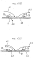
- Fig. 1 is an enlarged explanatory view of a film cooling hole structure of a gas turbine moving blade of a first embodiment, which is shown in contrast with the prior art film cooling hole structure of Fig. 4 as portion X of the moving blade of Fig. 5.
- FIG. 1 interior of a moving blade 20 is sectioned by a rib 51 to form cooling passage portions 22, 23 and cooling holes 50 are provided in a blade tip portion.
- This construction is same as that shown in Fig. 4.
- Featured portion of the present invention is cooling holes 1, 2 provided in the cooling passage as follows.
- the cooling hole 1 is a hole for effecting a film cooling, which is provided at the separation area 52 caused by a separation phenomenon of cooling air flow in a tip portion of the rib 51 of the gas turbine moving blade in the prior art shown in Fig. 4. Also, the cooling hole 2 is provided at the stagnation area 53 caused in a corner of the cooling passage portion 22 in the prior art.
- cooling air 41 flowing through the cooling passage portion 22 turns as shown by air 41e to flow into the adjacent cooling passage portion 23.
- the air flow separated from the tip portion of the rib 51 enters the cooling hole 1 provided at the separation area 52 as shown by air 41h.
- the cooling hole 1 is provided closely to or in contact with the tip portion of the rib 51 so as to be positioned in the area where the separation of air occurs to prevent a flow thereof, hence the cooling air 41h flows through this area to cool the separation area 52 effectively and the heat transfer rate there can be enhanced.
- the cooling air 41 partially flows to the stagnation area 53 in a tip corner portion of the cooling passage portion 22 and as the cooling hole 2 is provided in the stagnation area 53, the cooling air flows through the stagnation area 53, as shown by air 41i, to flow out of the blade.
- the cooling air flow arises in the stagnation area to cool this portion effectively and the heat transfer rate there can be enhanced.
- cooling holes 1, 2 may be provided newly in the separation area and the stagnation area or a portion of the film cooling holes provided conventionally may be moved to these areas to form the cooling holes 1, 2 and either way thereof may be employed as a matter of course.
- the cooling hole 1 is provided in the separation area 52 caused on the cooling passage portion 23 side in the turning portion of the cooling passage at the tip portion of the rib 51 between the cooling passage portions 22, 23 of the gas turbine moving blade in the prior art as well as the cooling hole 2 is provided in the stagnation area 53 caused in the tip corner portion of the cooling passage portion 22, thereby the heat transfer rate in the respective areas is enhanced, the cooling of the entire blade is made uniform and a reduction of the cooling air quantity and a life elongation of the blade can be realized.
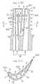
- Fig. 2 is a cross sectional plan view of another film cooling hole structure of a gas turbine moving blade, wherein Fig. 2(a) shows a second embodiment according to the present invention which is applied to the moving blade in the prior art shown in Fig. 7 and Fig. 2(b) shows a film cooling hole structure of the moving blade in the prior art shown in Fig. 7.
- Fig. 2(a) shows a second embodiment according to the present invention which is applied to the moving blade in the prior art shown in Fig. 7
- Fig. 2(b) shows a film cooling hole structure of the moving blade in the prior art shown in Fig. 7.
- the second embodiment may naturally be applied also to the moving blade in the prior art shown in Fig. 8.
- turbulators 28 in plural stages on a cooling passage inner wall 60 and also provided is a film cooling hole 61 between each of the turbulators 28 so as to pass through the blade to open in a blade outer surface.
- width or thickness of the turbulator 28 is e and distance between a cooling air downstream side surface of the turbulator and a center of the film cooling hole 61 is d, there is no specific rule to decide the relation between e and d in the present state of the film cooling hole but it is conventional to set d/e in a range of 10 to 20, that is, to provide the film cooling hole 61 around a central portion between each of the turbulators 28.
- cooling air 41 flows in the passage to be made turbulent by the turbulators 28 to thereby cool the blade with an enhanced heat transfer rate as well as the cooling air 41 is injected onto the blade outer surface from the film cooling holes 61 to thereby effect a film cooling of the blade surface.
- This separation area 62 is an area where the heat transfer rate is reduced, so that the cooling of the cooling passage becomes non-uniform and an effective cooling cannot be done.
- a film cooling hole 11 is provided close to or in contact with each of the turbulators 28 on the downstream side thereof so as to position in a range of 0 ⁇ d/e ⁇ 2. Construction of other portions of the second embodiment is same as that of the cooling passage in the prior art shown in Fig. 2(b).
- the flow separation area begins to be formed from when d/e is about 5 and this area is a low heat transfer area formed on a blade inner surface with the heat transfer rate being reduced by separation of the cooling air flow, hence if the film cooling hole 11 is provided at a position between a central portion of this low heat transfer area and a portion close to each of the turbulators 28, that is, a position where d/e is about 2 or less, so that the cooling air may flow into this film cooling hole 11, then a convection in this area is accelerated and the separation phenomenon can be dissolved effectively.
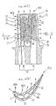
- FIG. 3 is an explanatory cross sectional side view showing an arrangement of the film cooling hole and a flow of the cooling air in a gas turbine moving blade, wherein Fig. 3(a) is of the second embodiment and Fig. 3(b) is of the prior art shown in Fig. 2(b).
- the turbulators 28 are provided on the cooling passage inner wall 60 and the cooling air 41 strikes this inner wall 60 to then flow in a space downstream thereof like air 41f.
- air 41g near each of the turbulators 28 on an upstream side thereof flows to join in the air 41f
- air near the turbulator 28 on a downstream side thereof turns like air 41h to cause the separation area 62 of air flow and this separation area 62 becomes a low heat transfer area to make the cooling non-uniform, which is one of the reasons to reduce the cooling performance of the entire blade.
- the film cooling hole 11 near each of the turbulators 28 on the downstream side thereof so as to position in the separation area 62.
- the air that wants to separate flows through the film cooling hole 11 to flow out to the blade outer surface like air 41e, and by this cooling air flow caused in the separation area 62, the cooling effect in this portion can be enhanced.
- the cooling air 41 strikes the blade inner wall to then flow over the turbulator 28 as the air 41f and cools the blade wall.
- the cooling air flows through the film cooling hole 11 provided near the turbulator 28 on the downstream side thereof to thereby accelerate a convection of the cooling air in the separation area 62 which would otherwise be caused and the cooling effect in this area can be enhanced.
- the cooling in the cooling passage is done uniformly and the cooling effect of the entire blade can be enhanced.
Landscapes
- Engineering & Computer Science (AREA)
- Mechanical Engineering (AREA)
- General Engineering & Computer Science (AREA)
- Turbine Rotor Nozzle Sealing (AREA)
Applications Claiming Priority (1)
| Application Number | Priority Date | Filing Date | Title |
|---|---|---|---|
| PCT/JP1999/005047 WO2001020133A1 (en) | 1999-09-16 | 1999-09-16 | Film cooling hole construction in gas turbine moving-vanes |
Publications (2)
| Publication Number | Publication Date |
|---|---|
| EP1132575A1 true EP1132575A1 (de) | 2001-09-12 |
| EP1132575A4 EP1132575A4 (de) | 2002-04-10 |
Family
ID=14236721
Family Applications (1)
| Application Number | Title | Priority Date | Filing Date |
|---|---|---|---|
| EP99943365A Withdrawn EP1132575A4 (de) | 1999-09-16 | 1999-09-16 | Konfiguration von filmkühlungsbohrungen in gasturbinenschaufeln |
Country Status (3)
| Country | Link |
|---|---|
| EP (1) | EP1132575A4 (de) |
| CA (1) | CA2347888A1 (de) |
| WO (1) | WO2001020133A1 (de) |
Cited By (2)
| Publication number | Priority date | Publication date | Assignee | Title |
|---|---|---|---|---|
| EP1362982A1 (de) | 2002-05-09 | 2003-11-19 | General Electric Company | Turbinenschaufel mit dreifach nach hinten gewundenen Kühlkanälen |
| CN104791020A (zh) * | 2015-04-23 | 2015-07-22 | 华能国际电力股份有限公司 | 一种具有纵向相交肋冷却结构的燃气透平叶片 |
Families Citing this family (1)
| Publication number | Priority date | Publication date | Assignee | Title |
|---|---|---|---|---|
| US7235122B2 (en) | 2004-11-08 | 2007-06-26 | E. I. Du Pont De Nemours And Company | Filtration media for filtering particulate material from gas streams |
Family Cites Families (6)
| Publication number | Priority date | Publication date | Assignee | Title |
|---|---|---|---|---|
| GB1350424A (en) * | 1971-07-02 | 1974-04-18 | Rolls Royce | Cooled blade for a gas turbine engine |
| GB1564608A (en) * | 1975-12-20 | 1980-04-10 | Rolls Royce | Means for cooling a surface by the impingement of a cooling fluid |
| GB2165315B (en) * | 1984-10-04 | 1987-12-31 | Rolls Royce | Improvements in or relating to hollow fluid cooled turbine blades |
| JPS62228603A (ja) * | 1986-03-31 | 1987-10-07 | Toshiba Corp | ガスタ−ビンの翼 |
| US4930980A (en) * | 1989-02-15 | 1990-06-05 | Westinghouse Electric Corp. | Cooled turbine vane |
| JPH11257005A (ja) * | 1998-03-16 | 1999-09-21 | Mitsubishi Heavy Ind Ltd | ガスタービン動翼のフィルム冷却穴構造 |
-
1999
- 1999-09-16 CA CA002347888A patent/CA2347888A1/en not_active Abandoned
- 1999-09-16 EP EP99943365A patent/EP1132575A4/de not_active Withdrawn
- 1999-09-16 WO PCT/JP1999/005047 patent/WO2001020133A1/ja not_active Ceased
Cited By (3)
| Publication number | Priority date | Publication date | Assignee | Title |
|---|---|---|---|---|
| EP1362982A1 (de) | 2002-05-09 | 2003-11-19 | General Electric Company | Turbinenschaufel mit dreifach nach hinten gewundenen Kühlkanälen |
| CN104791020A (zh) * | 2015-04-23 | 2015-07-22 | 华能国际电力股份有限公司 | 一种具有纵向相交肋冷却结构的燃气透平叶片 |
| CN104791020B (zh) * | 2015-04-23 | 2016-06-15 | 华能国际电力股份有限公司 | 一种具有纵向相交肋冷却结构的燃气透平叶片 |
Also Published As
| Publication number | Publication date |
|---|---|
| CA2347888A1 (en) | 2001-03-22 |
| EP1132575A4 (de) | 2002-04-10 |
| WO2001020133A1 (en) | 2001-03-22 |
| WO2001020133A8 (en) | 2001-07-26 |
Similar Documents
| Publication | Publication Date | Title |
|---|---|---|
| US6474947B1 (en) | Film cooling hole construction in gas turbine moving-vanes | |
| US6616406B2 (en) | Airfoil trailing edge cooling construction | |
| US7137776B2 (en) | Film cooling for microcircuits | |
| US10808551B2 (en) | Airfoil cooling circuits | |
| KR100553295B1 (ko) | 터빈블레이드 | |
| US7997868B1 (en) | Film cooling hole for turbine airfoil | |
| US6602052B2 (en) | Airfoil tip squealer cooling construction | |
| AU2003204539B2 (en) | Linked, manufacturable, non-plugging microcircuits | |
| US7121787B2 (en) | Turbine nozzle trailing edge cooling configuration | |
| JP2002364305A (ja) | タービンエンジン用の冷却可能なブレードまたはベーン | |
| KR20000070801A (ko) | 가스 터빈 에어포일을 냉각하는 장치 및 그 제조 방법 | |
| JP2006112429A (ja) | ガスタービンエンジン部品 | |
| JPS60192802A (ja) | ガスタ−ビン翼 | |
| US7311498B2 (en) | Microcircuit cooling for blades | |
| JP2010502872A (ja) | 冷却形タービン動翼 | |
| EP0927814A1 (de) | Deckband für gekühlte gasturbinenschaufeln | |
| JP2005337259A (ja) | ロータブレード | |
| JP4064778B2 (ja) | ガスタービン翼体およびガスタービン | |
| JP2005337256A (ja) | ロータブレード | |
| EP1132575A1 (de) | Konfiguration von filmkühlungsbohrungen in gasturbinenschaufeln | |
| JPS59113204A (ja) | 冷却翼 | |
| JPH11193701A (ja) | タービン翼 | |
| EP0921276B1 (de) | Gasturbinenschaufel | |
| JPH10252405A (ja) | 冷却動翼 | |
| JP3642537B2 (ja) | ガスタービン冷却翼 |
Legal Events
| Date | Code | Title | Description |
|---|---|---|---|
| PUAI | Public reference made under article 153(3) epc to a published international application that has entered the european phase |
Free format text: ORIGINAL CODE: 0009012 |
|
| 17P | Request for examination filed |
Effective date: 20010510 |
|
| AK | Designated contracting states |
Kind code of ref document: A1 Designated state(s): AT BE CH CY DE DK ES FI FR GB GR IE IT LI LU MC NL PT SE |
|
| AX | Request for extension of the european patent |
Free format text: AL;LT;LV;MK;RO;SI |
|
| A4 | Supplementary search report drawn up and despatched |
Effective date: 20020222 |
|
| AK | Designated contracting states |
Kind code of ref document: A4 Designated state(s): AT BE CH CY DE DK ES FI FR GB GR IE IT LI LU MC NL PT SE |
|
| 17Q | First examination report despatched |
Effective date: 20030923 |
|
| RBV | Designated contracting states (corrected) |
Designated state(s): CH DE FR GB LI |
|
| STAA | Information on the status of an ep patent application or granted ep patent |
Free format text: STATUS: THE APPLICATION IS DEEMED TO BE WITHDRAWN |
|
| 18D | Application deemed to be withdrawn |
Effective date: 20040204 |