EP1134417A2 - Verdrängerpumpe - Google Patents
Verdrängerpumpe Download PDFInfo
- Publication number
- EP1134417A2 EP1134417A2 EP01104428A EP01104428A EP1134417A2 EP 1134417 A2 EP1134417 A2 EP 1134417A2 EP 01104428 A EP01104428 A EP 01104428A EP 01104428 A EP01104428 A EP 01104428A EP 1134417 A2 EP1134417 A2 EP 1134417A2
- Authority
- EP
- European Patent Office
- Prior art keywords
- wing
- displacement pump
- pump according
- housing space
- sealing strips
- Prior art date
- Legal status (The legal status is an assumption and is not a legal conclusion. Google has not performed a legal analysis and makes no representation as to the accuracy of the status listed.)
- Granted
Links
- 238000006073 displacement reaction Methods 0.000 title claims abstract description 24
- 238000007789 sealing Methods 0.000 claims abstract description 53
- 230000002093 peripheral effect Effects 0.000 claims description 13
- 230000006835 compression Effects 0.000 claims description 6
- 238000007906 compression Methods 0.000 claims description 6
- 238000010276 construction Methods 0.000 description 7
- 239000000919 ceramic Substances 0.000 description 4
- 230000008859 change Effects 0.000 description 3
- 239000004033 plastic Substances 0.000 description 3
- 239000004696 Poly ether ether ketone Substances 0.000 description 2
- 239000004734 Polyphenylene sulfide Substances 0.000 description 2
- 229920010524 Syndiotactic polystyrene Polymers 0.000 description 2
- 230000008901 benefit Effects 0.000 description 2
- 238000005516 engineering process Methods 0.000 description 2
- 239000012530 fluid Substances 0.000 description 2
- 229920002530 polyetherether ketone Polymers 0.000 description 2
- 229920000069 polyphenylene sulfide Polymers 0.000 description 2
- 239000004721 Polyphenylene oxide Substances 0.000 description 1
- UCKMPCXJQFINFW-UHFFFAOYSA-N Sulphide Chemical compound [S-2] UCKMPCXJQFINFW-UHFFFAOYSA-N 0.000 description 1
- 230000006978 adaptation Effects 0.000 description 1
- 238000005452 bending Methods 0.000 description 1
- 230000015572 biosynthetic process Effects 0.000 description 1
- 238000009826 distribution Methods 0.000 description 1
- 230000000694 effects Effects 0.000 description 1
- 238000004146 energy storage Methods 0.000 description 1
- 238000007373 indentation Methods 0.000 description 1
- 238000001746 injection moulding Methods 0.000 description 1
- 230000003993 interaction Effects 0.000 description 1
- 239000007788 liquid Substances 0.000 description 1
- 238000004519 manufacturing process Methods 0.000 description 1
- 239000000463 material Substances 0.000 description 1
- 230000007246 mechanism Effects 0.000 description 1
- 239000002184 metal Substances 0.000 description 1
- 238000000034 method Methods 0.000 description 1
- 239000002991 molded plastic Substances 0.000 description 1
- 230000000149 penetrating effect Effects 0.000 description 1
- 229920000570 polyether Polymers 0.000 description 1
- 238000003825 pressing Methods 0.000 description 1
- 230000008569 process Effects 0.000 description 1
- 238000005086 pumping Methods 0.000 description 1
- 238000000926 separation method Methods 0.000 description 1
- 238000005507 spraying Methods 0.000 description 1
Images


Classifications
-
- F—MECHANICAL ENGINEERING; LIGHTING; HEATING; WEAPONS; BLASTING
- F04—POSITIVE - DISPLACEMENT MACHINES FOR LIQUIDS; PUMPS FOR LIQUIDS OR ELASTIC FLUIDS
- F04C—ROTARY-PISTON, OR OSCILLATING-PISTON, POSITIVE-DISPLACEMENT MACHINES FOR LIQUIDS; ROTARY-PISTON, OR OSCILLATING-PISTON, POSITIVE-DISPLACEMENT PUMPS
- F04C2/00—Rotary-piston machines or pumps
- F04C2/30—Rotary-piston machines or pumps having the characteristics covered by two or more groups F04C2/02, F04C2/08, F04C2/22, F04C2/24 or having the characteristics covered by one of these groups together with some other type of movement between co-operating members
- F04C2/34—Rotary-piston machines or pumps having the characteristics covered by two or more groups F04C2/02, F04C2/08, F04C2/22, F04C2/24 or having the characteristics covered by one of these groups together with some other type of movement between co-operating members having the movement defined in groups F04C2/08 or F04C2/22 and relative reciprocation between the co-operating members
- F04C2/344—Rotary-piston machines or pumps having the characteristics covered by two or more groups F04C2/02, F04C2/08, F04C2/22, F04C2/24 or having the characteristics covered by one of these groups together with some other type of movement between co-operating members having the movement defined in groups F04C2/08 or F04C2/22 and relative reciprocation between the co-operating members with vanes reciprocating with respect to the inner member
- F04C2/3441—Rotary-piston machines or pumps having the characteristics covered by two or more groups F04C2/02, F04C2/08, F04C2/22, F04C2/24 or having the characteristics covered by one of these groups together with some other type of movement between co-operating members having the movement defined in groups F04C2/08 or F04C2/22 and relative reciprocation between the co-operating members with vanes reciprocating with respect to the inner member the inner and outer member being in contact along one line or continuous surface substantially parallel to the axis of rotation
-
- F—MECHANICAL ENGINEERING; LIGHTING; HEATING; WEAPONS; BLASTING
- F01—MACHINES OR ENGINES IN GENERAL; ENGINE PLANTS IN GENERAL; STEAM ENGINES
- F01C—ROTARY-PISTON OR OSCILLATING-PISTON MACHINES OR ENGINES
- F01C21/00—Component parts, details or accessories not provided for in groups F01C1/00 - F01C20/00
- F01C21/08—Rotary pistons
-
- F—MECHANICAL ENGINEERING; LIGHTING; HEATING; WEAPONS; BLASTING
- F01—MACHINES OR ENGINES IN GENERAL; ENGINE PLANTS IN GENERAL; STEAM ENGINES
- F01C—ROTARY-PISTON OR OSCILLATING-PISTON MACHINES OR ENGINES
- F01C21/00—Component parts, details or accessories not provided for in groups F01C1/00 - F01C20/00
- F01C21/08—Rotary pistons
- F01C21/0809—Construction of vanes or vane holders
-
- F—MECHANICAL ENGINEERING; LIGHTING; HEATING; WEAPONS; BLASTING
- F01—MACHINES OR ENGINES IN GENERAL; ENGINE PLANTS IN GENERAL; STEAM ENGINES
- F01C—ROTARY-PISTON OR OSCILLATING-PISTON MACHINES OR ENGINES
- F01C21/00—Component parts, details or accessories not provided for in groups F01C1/00 - F01C20/00
- F01C21/08—Rotary pistons
- F01C21/0809—Construction of vanes or vane holders
- F01C21/0881—Construction of vanes or vane holders the vanes consisting of two or more parts
-
- F—MECHANICAL ENGINEERING; LIGHTING; HEATING; WEAPONS; BLASTING
- F04—POSITIVE - DISPLACEMENT MACHINES FOR LIQUIDS; PUMPS FOR LIQUIDS OR ELASTIC FLUIDS
- F04C—ROTARY-PISTON, OR OSCILLATING-PISTON, POSITIVE-DISPLACEMENT MACHINES FOR LIQUIDS; ROTARY-PISTON, OR OSCILLATING-PISTON, POSITIVE-DISPLACEMENT PUMPS
- F04C18/00—Rotary-piston pumps specially adapted for elastic fluids
- F04C18/30—Rotary-piston pumps specially adapted for elastic fluids having the characteristics covered by two or more of groups F04C18/02, F04C18/08, F04C18/22, F04C18/24, F04C18/48, or having the characteristics covered by one of these groups together with some other type of movement between co-operating members
- F04C18/34—Rotary-piston pumps specially adapted for elastic fluids having the characteristics covered by two or more of groups F04C18/02, F04C18/08, F04C18/22, F04C18/24, F04C18/48, or having the characteristics covered by one of these groups together with some other type of movement between co-operating members having the movement defined in group F04C18/08 or F04C18/22 and relative reciprocation between the co-operating members
- F04C18/344—Rotary-piston pumps specially adapted for elastic fluids having the characteristics covered by two or more of groups F04C18/02, F04C18/08, F04C18/22, F04C18/24, F04C18/48, or having the characteristics covered by one of these groups together with some other type of movement between co-operating members having the movement defined in group F04C18/08 or F04C18/22 and relative reciprocation between the co-operating members with vanes reciprocating with respect to the inner member
- F04C18/3441—Rotary-piston pumps specially adapted for elastic fluids having the characteristics covered by two or more of groups F04C18/02, F04C18/08, F04C18/22, F04C18/24, F04C18/48, or having the characteristics covered by one of these groups together with some other type of movement between co-operating members having the movement defined in group F04C18/08 or F04C18/22 and relative reciprocation between the co-operating members with vanes reciprocating with respect to the inner member the inner and outer member being in contact along one line or continuous surface substantially parallel to the axis of rotation
- F04C18/3442—Rotary-piston pumps specially adapted for elastic fluids having the characteristics covered by two or more of groups F04C18/02, F04C18/08, F04C18/22, F04C18/24, F04C18/48, or having the characteristics covered by one of these groups together with some other type of movement between co-operating members having the movement defined in group F04C18/08 or F04C18/22 and relative reciprocation between the co-operating members with vanes reciprocating with respect to the inner member the inner and outer member being in contact along one line or continuous surface substantially parallel to the axis of rotation the surfaces of the inner and outer member, forming the inlet and outlet opening
-
- F—MECHANICAL ENGINEERING; LIGHTING; HEATING; WEAPONS; BLASTING
- F04—POSITIVE - DISPLACEMENT MACHINES FOR LIQUIDS; PUMPS FOR LIQUIDS OR ELASTIC FLUIDS
- F04C—ROTARY-PISTON, OR OSCILLATING-PISTON, POSITIVE-DISPLACEMENT MACHINES FOR LIQUIDS; ROTARY-PISTON, OR OSCILLATING-PISTON, POSITIVE-DISPLACEMENT PUMPS
- F04C2/00—Rotary-piston machines or pumps
- F04C2/30—Rotary-piston machines or pumps having the characteristics covered by two or more groups F04C2/02, F04C2/08, F04C2/22, F04C2/24 or having the characteristics covered by one of these groups together with some other type of movement between co-operating members
- F04C2/34—Rotary-piston machines or pumps having the characteristics covered by two or more groups F04C2/02, F04C2/08, F04C2/22, F04C2/24 or having the characteristics covered by one of these groups together with some other type of movement between co-operating members having the movement defined in groups F04C2/08 or F04C2/22 and relative reciprocation between the co-operating members
- F04C2/344—Rotary-piston machines or pumps having the characteristics covered by two or more groups F04C2/02, F04C2/08, F04C2/22, F04C2/24 or having the characteristics covered by one of these groups together with some other type of movement between co-operating members having the movement defined in groups F04C2/08 or F04C2/22 and relative reciprocation between the co-operating members with vanes reciprocating with respect to the inner member
- F04C2/3441—Rotary-piston machines or pumps having the characteristics covered by two or more groups F04C2/02, F04C2/08, F04C2/22, F04C2/24 or having the characteristics covered by one of these groups together with some other type of movement between co-operating members having the movement defined in groups F04C2/08 or F04C2/22 and relative reciprocation between the co-operating members with vanes reciprocating with respect to the inner member the inner and outer member being in contact along one line or continuous surface substantially parallel to the axis of rotation
- F04C2/3442—Rotary-piston machines or pumps having the characteristics covered by two or more groups F04C2/02, F04C2/08, F04C2/22, F04C2/24 or having the characteristics covered by one of these groups together with some other type of movement between co-operating members having the movement defined in groups F04C2/08 or F04C2/22 and relative reciprocation between the co-operating members with vanes reciprocating with respect to the inner member the inner and outer member being in contact along one line or continuous surface substantially parallel to the axis of rotation the surfaces of the inner and outer member, forming the working space, being surfaces of revolution
Definitions
- the invention relates to a displacer with a wing mutual separation of the two chambers in the housing of the Pump housing, with the features of the preamble of Claim 1.
- Fig. 2A is already one Displacement pump known, the two chambers of the Pump housing space separating, positively guided Wings at both ends one in Wing longitudinally guided and on the Sealing strip adjacent to the inner circumferential wall of the housing space wearing.
- these are in Cross-section T-shaped, the T-beam is convexly curved on the outside in cross section and accordingly the peripheral wall only along a surface line touched.
- the middle ledge is with one in the wing Longitudinal groove formed on the face in the longitudinal direction of the wing engaged movably so that the Sealing strips when the drive shaft rotates below Centrifugal force automatically to the Create the inner circumferential wall.
- Positive displacement pumps of this embodiment are therefore suitable e.g. B. not for the evacuation of a brake booster a motor vehicle, since in this case even small ones Speeds an evacuation must be ensured.
- the object underlying the invention now exists in specifying a positive displacement pump in which then A subsidy starts when the speed is> 0 or when starting the pump driven by the motor the centrifugal force is not yet sufficient to the sealing strips of the wing in its maximum, radial sealing position relocate.
- the wing is equipped with an energy accumulator causes permanent contact even when the wave is at a standstill both sealing strips with the peripheral wall of the Housing space is secured, so that right from the start a shaft rotation displaces or is promoted.
- the wing on the drive shaft or in one of these driven pump rotor radially be guided displaceably, wherein, as explained above, may already be sufficient between the wing and only one of its sealing strips an energy accumulator to arrange.
- both sealing strips are preferably provided movable in the longitudinal direction of the wing and each of supported an energy store.
- the sliding arrangement of the sealing strips can 2A of DE 41 07 720 A1.
- the energy accumulator could each between Groove base of the wing groove and the web of the T-beam Sealing strips must be interposed.
- a preferred, slidable sealing strip arrangement on the wing is the subject of claim 3.
- This Construction offers on the one hand the possibility of Injection molding process of sash and sealing strips Shaped slide for the formation of the slide end as well the guide grooves to be provided on the performance side are waived can.
- stand out with this construction placed on or overlapping the wing ends Sealing strips made from a greater stability the bending moments resulting from the radial support forces the wing rotation from the U-legs of the sealing strips can be included cheaply.
- the energy accumulator designed as a leaf spring can be position advantageously according to claim 4, wherein wings and sealing strips in the lateral direction at the same time stay exactly aligned with each other.
- An alternative energy storage arrangement has claim 5 for Object.
- This construction offers above all Advantages if the housing space from the circular cylindrical Circumferential shape is very different and therefore around the sealing strip or strips during wing rotation relatively large radial paths have to be shifted.
- Wing construction is the subject of claim 6, by which is a sliding arrangement of the sealing strips superfluous on the wing ends in the longitudinal direction of the wing.
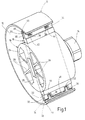
- the positive displacement pump according to FIG. 1 comprises in a known manner Way, a pump housing 10, one in its z. B. circular cylindrical housing space 12 eccentrically mounted Pump rotor 16, which is rotatably connected to a drive shaft 14 is connected in a rotationally fixed manner and radially in this slidably guided rotor blades 18 which at its Wing ends each carries a sealing strip 20 or 22.
- the pump rotor 16 preferably has one hollow cylindrical rotor shell 24 in which one inner ones extending along its inner diameter Wing guide strip 26 is provided in which Rotor blade 18 is received radially. 28 denotes inner rotor webs for stiffening the Rotor shell.
- the rotor 16 is towards the drive shaft 14 Slotted guide for the wing 18 and on the shaft 14 attached, inserted or molded.
- the housing space 12 is what is not, for the sake of simplicity is shown, tightly closed on both ends, the drive shaft 14 the one housing end wall penetrated liquid-tight.
- At the housing space 12 are also an inflow and an outflow line connected to a fluid to be promoted To be able to supply and discharge positive displacement pump.
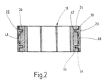
- the sealing strips 20, 22 of the rotor blade 18 are in the Cross section preferably U-shaped and overlap one with their U-legs 30, 32 the wing tips preferably over the entire Wing width molded guide bar 34.
- these are preferred with two spaced apart and parallel to each other provided guide pieces 36, 38 equipped to molded the connecting web 40 of their U-legs 30, 32 are and extend parallel to them, their Length is preferably less than that of the U-leg 30, 32.
- the guide pieces 36, 38 each engage in one blind hole-like indentation 42 and 44 and so also an exact alignment of the sealing strips 20, 22 transversely to the longitudinal direction of the wing.
- the U-leg connecting web 40 of the sealing strips 20, 22 is preferably designed in cross section so that it At the same time, a sealing edge 46 is defined on the outside.
- an energy store preferably in the form a leaf spring 48 is provided, which constantly tries the relevant sealing strip 20 or 22 in the direction of To shift or circumferential inner wall of the housing space 12 to keep in touch with this.
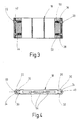
- a compression spring 50 or 52 can be introduced, on which the ledge guide pieces 36, 38 are supported (FIG. 3).
- the rotor blades 18 and the sealing strips 20, 22 are preferably designed as a molded plastic part, the Rotor blades 18 in particular for the purpose of being more uniform Material distribution during the spraying process, for example with three of these in the transverse direction parallel to its flat sides penetrating, flat slot-like recesses 54 Is provided.
- the pump rotor 16 can be in the housing space 12 also be centrally stored, provided the latter is oval Has peripheral shape.
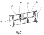
- the positive displacement pump according to FIGS. 5 and 6 comprises one Flange body with a pump housing 61 forming Cylinder pot 62, one stored in it Pump drive shaft 63 with attached rotor 64 and one in a recess running across the center of the rotor guided, divided as a whole with 65, divided into two Wing. As shown in FIG. 7, this is preferably through symmetrical, flat wing sections 65 ', 65' 'formed, which each have a pivot bearing at their outer end, on which a sealing strip 66 about an axis of rotation of the rotor parallel axis is pivotally mounted.
- the sealing strips 66 face the wall of the cylinder pot 62 provided with a concave radius 68 (Fig. 5). Consequently there are two lines of contact at 69 and 70, which in Interaction with the flat wing sections 65 ', 65' ' to seal the chambers in front of and behind the wing 65 serve. Radii 71 are at the ends of the sealing strips 66 and 72 are provided, which ensures optimal resealing is achieved.
- the rotor 64 is towards the drive shaft 63 as a guide for slotted the wing 65 and plugged onto the shaft 63, inserted or molded.
- This change in length is due to the radial mobility of the Wing sections 65 ', 65' 'balanced.
- the adaptation to the variable length in the angle of rotation happens through that Pressing the sealing strips 66 and taking the Wing 65 through the drive shaft 63 through the shaped spring 67 or by a corresponding compression spring, which the Wing sections 65 ', 65' 'apart and with this connected sealing strips 66 to the Pressed on cylinder wall.
- Rotor blades 18; 65, wing sections 65 ', 65' ', Sealing strips 20, 22; 66 and rotor 18; 64 can advantageously made of metal, plastic, ceramic, metal-plastic connection, Metal-ceramic connection, metal-plastic-ceramic connection or plastic-ceramic connection getting produced.
- PEEK polyether ether ketone
- PES polyether sulfide
- SPS syndiotactic polystyrene
- PPS polyphenylene sulfide
Landscapes
- Engineering & Computer Science (AREA)
- Mechanical Engineering (AREA)
- General Engineering & Computer Science (AREA)
- Rotary Pumps (AREA)
- Details And Applications Of Rotary Liquid Pumps (AREA)
- Electrically Driven Valve-Operating Means (AREA)
- Structures Of Non-Positive Displacement Pumps (AREA)
Abstract
Description
- Figur 1
- in schaubildlicher, aufgebrochener Darstellung einer Verdrängerpumpe mit einem, einen erfindungsgemäß ausgebildeten Flügel aufweisenden Pumpenrotor,
- Figur 2
- einen Längsschnitt des Rotorflügels gemäß Fig. 1,
- Figur 3
- einen Längsschnitt durch eine Konstruktionsvariante des Rotorflügels,
- Figur 4
- eine Ansicht auf eine Flügellängskante,
- Figur 5
- eine schaubildliche Ansicht in den geöffneten Gehäuseraum einer Verdrängerpumpe, deren Flügel ein weiteres Ausführungsbeispiel der Erfindung darstellt,
- Figur 6
- eine Seitenansicht der Verdrängerpumpe gemäß Figur 5,
- Figur 7
- eine perspektivische Darstellung des aus zwei Flügelteilstücken gebildeten Pumpenflügels.
Claims (13)
- Verdrängungspumpe (18, 65) mit einem Flügel zum gegenseitigen Trennen der beiden Kammern im Gehäuseraum (12, 62), der von einer im Pumpengehäuse (10, 61) gelagerten Antriebswelle (14, 63) antreibbar und zu dieser in einer deren Achse enthaltenden Ebene radial verschiebbar geführt ist und der endseitig jeweils eine mit der Innenumfangswand des Gehäuseraumes (12, 62) abdichtend zusammenwirkende Abdichtleiste (20 bzw. 22; 66) trägt, die zur Achse der Antriebswelle (14, 63) voneinander unabhängig radial beweglich sind, dadurch gekennzeichnet, dass am Flügel (18, 65) wenigstens ein Kraftspeicher (48 bzw. 67) vorgesehen ist, der versucht, beide Abdichtleisten (20, 22; 66) ständig mit der Innenumfangswand des Gehäuseraumes (12, 62) abdichtend in Berührung zu halten.
- Verdrängungspumpe nach Anspruch 1, dadurch gekennzeichnet, dass der Kraftspeicher (48) zwischen dem Flügel (18) und einer an diesem in Flügellängsrichtung verschiebbaren Abdichtleiste (20 bzw. 22) vorgesehen ist.
- Verdrängungspumpe nach Anspruch 2, dadurch gekennzeichnet, dass die verschiebbare Abdichtleiste (20 bzw. 22) im Querschnitt U-förmig ist und einen am Flügelende stirnseitig vorgesehenen Führungssteg (34) übergreift und dass der Kraftspeicher eine sich am Verbindungssteg (40) der U-Schenkel (30, 32) der Abdichtleiste (20 bzw. 22) abstützende Blattfeder (48) ist.
- Verdrängungspumpe nach Anspruch 3, dadurch gekennzeichnet, dass die Blattfeder (48) zwischen zwei sich vom Verbindungssteg (40) der U-Schenkel (30, 32) zu diesen parallel wegerstreckenden Führungsstücken (36, 38) angeordnet ist, die jeweils mit einer Vertiefung (42 bzw. 44) des Führungssteges (34) verschiebbar in Eingriff sind.
- Verdrängungspumpe nach Anspruch (3), dadurch gekennzeichnet, dass zwischen den U-Schenkeln (30, 32) der Abdichtleiste (20 bzw. 22), zu diesen parallel und in seitlichem Abstand voneinander, zwei sich jeweils mit einer Vertiefung (42 bzw. 44) des Führungssteges (34) verschiebbar in Eingriff befindliche Führungsstücke (36, 38) vorgesehen sind und dass zwischen den Führungsstücken (36, 38) und dem Boden der Vertiefungen (42, 44) jeweils eine die Abdichtleiste (20 bzw. 22) abstützende Schraubenfeder (50 bzw. 52) angeordnet ist.
- Verdrängungspumpe nach Anspruch 1, dadurch gekennzeichnet, dass der Flügel (65) in einem Schlitz eines im Gehäuseraum (62) gelagerten und von der Antriebswelle (63) antreibbaren Rotors (64) geführt ist, welcher Schlitz symmetrisch in einer die Rotorachse enthaltenden Ebene liegt, dass an den Flügelenden die sich an der Innenumfangsfläche des Gehäuseraumes (62) abstützenden Abdichtleisten (66) verschwenkbar gelagert sind und dass der Flügel (65) durch zwei zueinander fluchtende und voneinander unabhängig bewegliche Flügelteilstücke (65', 65") gebildet ist, zwischen denen der Kraftspeicher (67) angeordnet ist.
- Verdrängungspumpe nach Anspruch 6, dadurch gekennzeichnet, dass die Flügelteilstücke (65', 65'') symmetrisch ausgebildet sind.
- Verdrängungspumpe nach Anspruch 7, dadurch gekennzeichnet, dass die Flügelteilstücke (65', 65") ein Flachprofil aufweisen.
- Verdrängungspumpe nach einem der vorhergehenden Ansprüche 6 - 8, dadurch gekennzeichnet, dass die Flügelteilstücke (65', 65'') an ihren einander zugekehrten Stirnenden symmetrisch abgestuft sind und dass sich die Stirnenden jeweils an einem Schenkel einer zwischen diese eingelegten, Z-förmigen Feder (67) abstützen.
- Verdrängungspumpe nach einem der vorhergehenden Ansprüche 6 - 8, dadurch gekennzeichnet, dass die Flügelteilstücke (65', 65") an ihren einander zugekehrten Stirnenden nut- und federartig miteinander in Eingriff sind und dass zwischen diesen eine Druckfeder angeordnet ist.
- Verdrängungspumpe nach einem der vorhergehenden Ansprüche 6 - 10, dadurch gekennzeichnet, dass die Abdichtleisten (66) mit der Innenumfangsfläche des Gehäuseraumes (62), in Umfangsrichtung gesehen, eine Zwei-Linien-Berührung (69, 70) haben.
- Verdrängungspumpe nach Anspruch 11, dadurch gekennzeichnet, dass die der Innenumfangsfläche zugekehrte Seite der Abdichtleisten (66) in Umfangsrichtung des Gehäuseraumes (62) konkav gekrümmt ist.
- Verdrängungspumpe nach einem der vorhergehenden Ansprüche 6 - 12, dadurch gekennzeichnet, dass die zylindrische Innenumfangsfläche des Gehäuseraumes (62) ovale Umfangsform hat.
Priority Applications (2)
| Application Number | Priority Date | Filing Date | Title |
|---|---|---|---|
| EP03008524A EP1327778A3 (de) | 2000-03-15 | 2001-02-27 | Flügelzellenpumpe |
| EP04004782A EP1424495A3 (de) | 2000-03-15 | 2001-02-27 | Flügelzellenpumpe |
Applications Claiming Priority (4)
| Application Number | Priority Date | Filing Date | Title |
|---|---|---|---|
| DE10012406 | 2000-03-15 | ||
| DE2000112406 DE10012406A1 (de) | 2000-03-15 | 2000-03-15 | Vakuumpumpe |
| DE20018958U DE20018958U1 (de) | 2000-11-07 | 2000-11-07 | Schieber zum gegenseitigen Trennen der beiden Kammern im Gehäuseraum einer Flügelzellenpumpe oder eines solchen Motors |
| DE20018958U | 2000-11-07 |
Related Child Applications (1)
| Application Number | Title | Priority Date | Filing Date |
|---|---|---|---|
| EP03008524.5 Division-Into | 2003-04-12 |
Publications (3)
| Publication Number | Publication Date |
|---|---|
| EP1134417A2 true EP1134417A2 (de) | 2001-09-19 |
| EP1134417A3 EP1134417A3 (de) | 2002-09-11 |
| EP1134417B1 EP1134417B1 (de) | 2003-09-24 |
Family
ID=26004832
Family Applications (3)
| Application Number | Title | Priority Date | Filing Date |
|---|---|---|---|
| EP01104428A Expired - Lifetime EP1134417B1 (de) | 2000-03-15 | 2001-02-27 | Verdrängerpumpe |
| EP04004782A Withdrawn EP1424495A3 (de) | 2000-03-15 | 2001-02-27 | Flügelzellenpumpe |
| EP03008524A Withdrawn EP1327778A3 (de) | 2000-03-15 | 2001-02-27 | Flügelzellenpumpe |
Family Applications After (2)
| Application Number | Title | Priority Date | Filing Date |
|---|---|---|---|
| EP04004782A Withdrawn EP1424495A3 (de) | 2000-03-15 | 2001-02-27 | Flügelzellenpumpe |
| EP03008524A Withdrawn EP1327778A3 (de) | 2000-03-15 | 2001-02-27 | Flügelzellenpumpe |
Country Status (5)
| Country | Link |
|---|---|
| US (1) | US6604924B2 (de) |
| EP (3) | EP1134417B1 (de) |
| CN (1) | CN1162621C (de) |
| AT (1) | ATE250722T1 (de) |
| DE (1) | DE50100666D1 (de) |
Cited By (6)
| Publication number | Priority date | Publication date | Assignee | Title |
|---|---|---|---|---|
| WO2002025113A1 (de) * | 2000-09-21 | 2002-03-28 | Robert Bosch Gmbh | Flügel aus kunststoff für eine flügelzellen-vakuumpumpe |
| EP1471255A1 (de) * | 2003-04-24 | 2004-10-27 | Joma-Hydromechanic GmbH | Flügelzellenpumpe |
| DE102004034921B3 (de) * | 2004-07-09 | 2005-12-29 | Joma-Hydromechanic Gmbh | Einflügelvakuumpumpe |
| EP1553299A3 (de) * | 2004-01-07 | 2006-01-11 | Joma-Hydromechanic GmbH | Verdrängerpumpe mit Flügel |
| EP2299055A1 (de) | 2009-09-14 | 2011-03-23 | Pierburg Pump Technology GmbH | Flügelzellen-Vakuumpumpe für Kraftfahrzeuge |
| DE102009035000B4 (de) * | 2009-07-27 | 2013-03-28 | Sergej Semakin | Flügelzellenmaschine |
Families Citing this family (24)
| Publication number | Priority date | Publication date | Assignee | Title |
|---|---|---|---|---|
| DE102004034922B4 (de) * | 2004-07-09 | 2006-05-11 | Joma-Hydromechanic Gmbh | Einflügelvakuumpumpe |
| DE102004034925B3 (de) * | 2004-07-09 | 2006-02-16 | Joma-Hydromechanic Gmbh | Einflügelvakuumpumpe |
| DE102004034926B3 (de) * | 2004-07-09 | 2005-12-29 | Joma-Hydromechanic Gmbh | Einflügelvakuumpumpe |
| GB0419496D0 (en) * | 2004-09-02 | 2004-10-06 | Wabco Automotive Uk Ltd | Improvements relating to vacuum pumps |
| DE102004053521A1 (de) * | 2004-10-29 | 2006-05-11 | Joma-Hydromechanic Gmbh | Flügel für eine Rotorpumpe |
| DE102005015721B3 (de) * | 2005-03-31 | 2006-12-21 | Joma-Hydromechanic Gmbh | Vakuumpumpe |
| ITMI20050685A1 (it) * | 2005-04-18 | 2006-10-19 | O M P Officine Mazzocco Pagnon | Pompa a palette per un motore per autoveicoli e paletta per tale pompa |
| DE102005050001A1 (de) * | 2005-10-13 | 2007-04-19 | Joma-Hydromechanic Gmbh | Rotorpumpe |
| DE102005056270B3 (de) * | 2005-11-14 | 2007-03-01 | Joma-Hydromechanic Gmbh | Rotorpumpe |
| DE102006016243A1 (de) * | 2006-03-31 | 2007-10-04 | Joma-Hydromechanic Gmbh | Rotorpumpe und Flügel für eine Rotorpumpe |
| CN101122365B (zh) * | 2006-08-08 | 2012-07-04 | 刘矗汀 | 流体通道上的穿轴叶块旋转式膨胀或压缩机构 |
| GB2486007B (en) * | 2010-12-01 | 2017-05-10 | Itt Mfg Enterprises Inc | Sliding vane pump |
| CN103930678B (zh) * | 2012-01-11 | 2016-03-30 | 三菱电机株式会社 | 叶片型压缩机 |
| WO2013131011A1 (en) * | 2012-03-01 | 2013-09-06 | Torad Engineering, Llc | Sealing element for rotary compressor |
| DE102012210048A1 (de) * | 2012-06-14 | 2013-12-19 | Joma-Polytec Gmbh | Verdrängerpumpe |
| DE202013000976U1 (de) * | 2013-02-01 | 2014-05-08 | Saeta Gmbh & Co. Kg | Flügel für eine Flügelzellenvorrichtung sowie Flügelzellenvorrichtung |
| DE102013215561A1 (de) * | 2013-08-07 | 2015-03-05 | Behr Gmbh & Co. Kg | Rotor für einen Elektromotor, Elektromotor und Klimaanlage |
| CN104131976A (zh) * | 2014-08-18 | 2014-11-05 | 王喜来 | 一种旋转式空压机 |
| DE102015213098B4 (de) * | 2015-07-13 | 2017-05-04 | Joma-Polytec Gmbh | Flügel für eine Flügelzellenpumpe und Flügelzellenpumpe |
| CN105864034B (zh) * | 2016-06-06 | 2019-06-21 | 陈继业 | 单滑片回转式容积泵 |
| CN109826788A (zh) * | 2019-01-31 | 2019-05-31 | 刘江 | 一种新型气、液泵 |
| CN110374874B (zh) * | 2019-07-29 | 2024-11-01 | 黄石东贝压缩机有限公司 | 一种多重防泄漏弹片式滑块机构 |
| CN110541826A (zh) * | 2019-10-21 | 2019-12-06 | 太仓束捍机电科技有限公司 | 一种真空束焊机用真空泵 |
| CN117759651A (zh) * | 2024-01-08 | 2024-03-26 | 长春工业大学 | 一种离合器分离泵转接支架 |
Citations (1)
| Publication number | Priority date | Publication date | Assignee | Title |
|---|---|---|---|---|
| DE4107720A1 (de) | 1990-03-10 | 1991-10-10 | Barmag Luk Automobiltech | Fluegelzellenpumpe |
Family Cites Families (36)
| Publication number | Priority date | Publication date | Assignee | Title |
|---|---|---|---|---|
| US620636A (en) * | 1899-03-07 | Rotary engine | ||
| US884747A (en) * | 1904-12-02 | 1908-04-14 | Creamery Package Mfg Co | Rotary pump. |
| US1078301A (en) * | 1910-01-12 | 1913-11-11 | Junius M Horner | Rotary engine. |
| DE329066C (de) * | 1912-09-18 | 1920-11-13 | Paul Schaefer | Abdichtung des Kolbens von Kraftmaschinen mit umlaufenden, in der Kolbentrommel verschiebbaren Kolben mittels Keilwirkung |
| US1528075A (en) * | 1921-08-11 | 1925-03-03 | Joseph R Richer | Rotary pump and the like |
| DE385561C (de) * | 1922-01-08 | 1923-11-26 | App Bauanstalt Axmann & Co G M | Kolbenentlastungsvorrichtung fuer Drehkolbenkraftmaschinen mit in geschlossenen Schlitzen der Trommel verschiebbaren Kolben |
| US1649256A (en) * | 1923-02-10 | 1927-11-15 | Rotary Machine & Engineering C | Rotary pump |
| GB222242A (en) * | 1923-07-09 | 1924-10-02 | William Rogan | Improvements in or relating to rotary pumps |
| FR590546A (fr) * | 1924-06-03 | 1925-06-18 | Pompe centrifuge utilisable, notamment, comme compresseur rotatif | |
| US1658524A (en) * | 1925-02-10 | 1928-02-07 | John W Gurley | Rotary pump |
| US1972864A (en) * | 1930-10-15 | 1934-09-11 | Bradshaw & Company | Rotary pump |
| US2103180A (en) * | 1933-06-15 | 1937-12-21 | Rice Mfg And Aerial Transp Cor | Rotary motor |
| US2436876A (en) * | 1943-07-29 | 1948-03-02 | Alfred L Stamsvik | Rotary sliding vane pump structure |
| GB605740A (en) * | 1946-12-20 | 1948-07-29 | Derek Eyre Kirkland | Improvements in or relating to sliding-vane rotary pumps |
| US2631546A (en) * | 1948-10-19 | 1953-03-17 | Edward A Dawson | Rotary sliding vane pump |
| CH381797A (de) * | 1959-03-10 | 1964-09-15 | Kron Werner | Drehkolbenmaschine |
| FR1315068A (fr) * | 1961-11-09 | 1963-01-18 | Moteur à combustion interne à piston rotatif | |
| US3386648A (en) * | 1967-01-31 | 1968-06-04 | Walter J. Van Rossem | Rotary vane type pump |
| US3452725A (en) * | 1967-08-23 | 1969-07-01 | Donald A Kelly | High compression rotary i.c. engine |
| CH466490A (de) * | 1967-10-18 | 1968-12-15 | Ryffel Hans | Drehschiebermaschine |
| GB1426126A (en) * | 1973-02-16 | 1976-02-25 | Komiya S | Movable vane type compressor |
| JPS5216011A (en) * | 1975-07-30 | 1977-02-07 | Shimadzu Corp | Moving vane type vacuum pump |
| JPS5598689A (en) * | 1979-01-23 | 1980-07-26 | Musashi Seimitsu Kogyo Kk | Vane at rotary compressor |
| IT1130363B (it) * | 1980-01-29 | 1986-06-11 | Leonardo Beltrame | Compressore a capsulismo con girante perfezionato,utile in particolare per gonfiaggio od alimentazione di avvisatoripneumatici per veicoli |
| DE3418928A1 (de) * | 1984-05-21 | 1986-02-20 | Günter 5600 Wuppertal Küller | Rotationskolbenpumpe zur befoerderung von luft |
| JPS6111482A (ja) * | 1984-06-27 | 1986-01-18 | Honda Motor Co Ltd | ベ−ンポンプ装置 |
| DE3537158A1 (de) * | 1984-10-26 | 1986-06-05 | Barmag Barmer Maschinenfabrik Ag, 5630 Remscheid | Verzahnte fluegelzellenpumpe |
| DE3504547A1 (de) * | 1985-02-11 | 1986-09-11 | Armatec FTS-Armaturen GmbH & Co KG, 7988 Wangen | Rotationsverdichter mit festverbundenen schieberhaelften |
| JPS62126286A (ja) * | 1985-11-25 | 1987-06-08 | Honda Motor Co Ltd | ベ−ン式回転圧縮機に於けるベ−ン構造 |
| DE3615102A1 (de) * | 1986-05-03 | 1987-11-05 | Wolfgang Dipl Ing Peylo | Drehkolbenbrennkraftmaschine |
| DE3628998A1 (de) * | 1986-08-26 | 1988-03-03 | Wuerth Gustav Dipl Kaufm Dr | Schieberkolben fuer rotations-kompressor |
| DE4033455A1 (de) * | 1990-10-20 | 1992-04-23 | Bosch Gmbh Robert | Fluegelzellenkompressor oder -pumpe |
| IT1293672B1 (it) * | 1997-08-01 | 1999-03-08 | Magneti Marelli Spa | Depressore rotativo a palette. |
| DE19844904C1 (de) * | 1998-09-30 | 2000-02-17 | Luk Automobiltech Gmbh & Co Kg | Vakuumpumpe |
| DE10046697A1 (de) * | 2000-09-21 | 2002-04-11 | Bosch Gmbh Robert | Flügel aus Kunststoff für eine Flügelzellen-Vakuumpumpe |
| DE10294902D2 (de) * | 2001-10-15 | 2004-09-16 | Luk Automobiltech Gmbh & Co Kg | Vakuumpumpe |
-
2001
- 2001-02-27 DE DE50100666T patent/DE50100666D1/de not_active Expired - Lifetime
- 2001-02-27 EP EP01104428A patent/EP1134417B1/de not_active Expired - Lifetime
- 2001-02-27 EP EP04004782A patent/EP1424495A3/de not_active Withdrawn
- 2001-02-27 AT AT01104428T patent/ATE250722T1/de not_active IP Right Cessation
- 2001-02-27 EP EP03008524A patent/EP1327778A3/de not_active Withdrawn
- 2001-03-14 US US09/808,304 patent/US6604924B2/en not_active Expired - Fee Related
- 2001-03-14 CN CNB011094974A patent/CN1162621C/zh not_active Expired - Fee Related
Patent Citations (1)
| Publication number | Priority date | Publication date | Assignee | Title |
|---|---|---|---|---|
| DE4107720A1 (de) | 1990-03-10 | 1991-10-10 | Barmag Luk Automobiltech | Fluegelzellenpumpe |
Cited By (8)
| Publication number | Priority date | Publication date | Assignee | Title |
|---|---|---|---|---|
| WO2002025113A1 (de) * | 2000-09-21 | 2002-03-28 | Robert Bosch Gmbh | Flügel aus kunststoff für eine flügelzellen-vakuumpumpe |
| EP1471255A1 (de) * | 2003-04-24 | 2004-10-27 | Joma-Hydromechanic GmbH | Flügelzellenpumpe |
| EP1553299A3 (de) * | 2004-01-07 | 2006-01-11 | Joma-Hydromechanic GmbH | Verdrängerpumpe mit Flügel |
| DE102004034921B3 (de) * | 2004-07-09 | 2005-12-29 | Joma-Hydromechanic Gmbh | Einflügelvakuumpumpe |
| DE102004034921B9 (de) * | 2004-07-09 | 2006-04-27 | Joma-Hydromechanic Gmbh | Einflügelvakuumpumpe |
| DE102004064029B4 (de) * | 2004-07-09 | 2008-04-10 | Joma-Hydromechanic Gmbh | Einflügelvakuumpumpe |
| DE102009035000B4 (de) * | 2009-07-27 | 2013-03-28 | Sergej Semakin | Flügelzellenmaschine |
| EP2299055A1 (de) | 2009-09-14 | 2011-03-23 | Pierburg Pump Technology GmbH | Flügelzellen-Vakuumpumpe für Kraftfahrzeuge |
Also Published As
| Publication number | Publication date |
|---|---|
| EP1424495A3 (de) | 2004-06-23 |
| CN1317644A (zh) | 2001-10-17 |
| CN1162621C (zh) | 2004-08-18 |
| ATE250722T1 (de) | 2003-10-15 |
| DE50100666D1 (de) | 2003-10-30 |
| US6604924B2 (en) | 2003-08-12 |
| EP1134417B1 (de) | 2003-09-24 |
| EP1424495A2 (de) | 2004-06-02 |
| US20020136656A1 (en) | 2002-09-26 |
| EP1327778A2 (de) | 2003-07-16 |
| EP1134417A3 (de) | 2002-09-11 |
| EP1327778A3 (de) | 2003-07-23 |
Similar Documents
| Publication | Publication Date | Title |
|---|---|---|
| EP1134417A2 (de) | Verdrängerpumpe | |
| EP2732165B1 (de) | Schraubenverdichter | |
| DE19613833B4 (de) | Innenzahnradmaschine, insbesondere Innenzahnradpumpe | |
| EP1361365B1 (de) | Vakuumpumpe und Kunststoffrotor | |
| EP2359005B1 (de) | Flügelzellenpumpe | |
| EP1295037B1 (de) | Flügelzellenpumpe | |
| DE102011078017B3 (de) | Pumpe | |
| DE19527647A1 (de) | Axialkolbenmaschine | |
| DE102006016791B4 (de) | Vakuumpumpe | |
| EP1766240B1 (de) | Einflügelvakuumpumpe | |
| EP1766237B1 (de) | Einflügelvakuumpumpe | |
| DE19703113C2 (de) | Hydraulische Flügelzellenmaschine | |
| DE102008045440B4 (de) | Drehkolben einer Drehkolbenpumpe und Drehkolbenpumpe | |
| EP2176519B1 (de) | Pendelschieber-vakuumpumpe | |
| EP1448895A1 (de) | Drehkolbenpumpe | |
| DE4107720C2 (de) | Flügelzellenpumpe | |
| EP3859159B1 (de) | Schraubenverdichter | |
| DE20018958U1 (de) | Schieber zum gegenseitigen Trennen der beiden Kammern im Gehäuseraum einer Flügelzellenpumpe oder eines solchen Motors | |
| DE4322584C2 (de) | Innenzahnradmaschine (Pumpe oder Motor) | |
| DE102017125632A1 (de) | Peristaltische Schlauchpumpe | |
| DE3922434C2 (de) | ||
| EP1118773A2 (de) | Flügelzellenpumpe oder Flügelzellenmotor | |
| DE102006016790B3 (de) | Zellenpumpe | |
| DE202007012565U1 (de) | Hybridpumpe zum Fördern eines flüssigen Pumpmediums | |
| EP2580477B1 (de) | Drehschieberpumpe |
Legal Events
| Date | Code | Title | Description |
|---|---|---|---|
| PUAI | Public reference made under article 153(3) epc to a published international application that has entered the european phase |
Free format text: ORIGINAL CODE: 0009012 |
|
| AK | Designated contracting states |
Kind code of ref document: A2 Designated state(s): AT BE CH CY DE DK ES FI FR GB GR IE IT LI LU MC NL PT SE TR |
|
| AX | Request for extension of the european patent |
Free format text: AL;LT;LV;MK;RO;SI |
|
| PUAL | Search report despatched |
Free format text: ORIGINAL CODE: 0009013 |
|
| AK | Designated contracting states |
Kind code of ref document: A3 Designated state(s): AT BE CH CY DE DK ES FI FR GB GR IE IT LI LU MC NL PT SE TR |
|
| AX | Request for extension of the european patent |
Free format text: AL;LT;LV;MK;RO;SI |
|
| 17P | Request for examination filed |
Effective date: 20020814 |
|
| 17Q | First examination report despatched |
Effective date: 20021114 |
|
| AKX | Designation fees paid |
Designated state(s): AT BE CH CY DE DK ES FI FR GB GR IE IT LI LU MC NL PT SE TR |
|
| GRAP | Despatch of communication of intention to grant a patent |
Free format text: ORIGINAL CODE: EPIDOSNIGR1 |
|
| RIN1 | Information on inventor provided before grant (corrected) |
Inventor name: JESCHONNEK PETER Inventor name: SCHNEIDER, WILLI, DIPL.-ING. Inventor name: SCHMID REINER |
|
| RAP1 | Party data changed (applicant data changed or rights of an application transferred) |
Owner name: JOMA-HYDROMECHANIC GMBH Owner name: BAYERISCHE MOTOREN WERKE AKTIENGESELLSCHAFT |
|
| GRAS | Grant fee paid |
Free format text: ORIGINAL CODE: EPIDOSNIGR3 |
|
| GRAA | (expected) grant |
Free format text: ORIGINAL CODE: 0009210 |
|
| AK | Designated contracting states |
Kind code of ref document: B1 Designated state(s): AT BE CH CY DE DK ES FI FR GB GR IE IT LI LU MC NL PT SE TR |
|
| PG25 | Lapsed in a contracting state [announced via postgrant information from national office to epo] |
Ref country code: TR Free format text: LAPSE BECAUSE OF FAILURE TO SUBMIT A TRANSLATION OF THE DESCRIPTION OR TO PAY THE FEE WITHIN THE PRESCRIBED TIME-LIMIT Effective date: 20030924 Ref country code: NL Free format text: LAPSE BECAUSE OF FAILURE TO SUBMIT A TRANSLATION OF THE DESCRIPTION OR TO PAY THE FEE WITHIN THE PRESCRIBED TIME-LIMIT Effective date: 20030924 Ref country code: FI Free format text: LAPSE BECAUSE OF FAILURE TO SUBMIT A TRANSLATION OF THE DESCRIPTION OR TO PAY THE FEE WITHIN THE PRESCRIBED TIME-LIMIT Effective date: 20030924 Ref country code: CY Free format text: LAPSE BECAUSE OF FAILURE TO SUBMIT A TRANSLATION OF THE DESCRIPTION OR TO PAY THE FEE WITHIN THE PRESCRIBED TIME-LIMIT Effective date: 20030924 Ref country code: IE Free format text: LAPSE BECAUSE OF FAILURE TO SUBMIT A TRANSLATION OF THE DESCRIPTION OR TO PAY THE FEE WITHIN THE PRESCRIBED TIME-LIMIT Effective date: 20030924 |
|
| REG | Reference to a national code |
Ref country code: GB Ref legal event code: FG4D Free format text: NOT ENGLISH |
|
| REG | Reference to a national code |
Ref country code: CH Ref legal event code: EP |
|
| GBT | Gb: translation of ep patent filed (gb section 77(6)(a)/1977) | ||
| REG | Reference to a national code |
Ref country code: IE Ref legal event code: FG4D Free format text: GERMAN |
|
| REF | Corresponds to: |
Ref document number: 50100666 Country of ref document: DE Date of ref document: 20031030 Kind code of ref document: P |
|
| PG25 | Lapsed in a contracting state [announced via postgrant information from national office to epo] |
Ref country code: DK Free format text: LAPSE BECAUSE OF FAILURE TO SUBMIT A TRANSLATION OF THE DESCRIPTION OR TO PAY THE FEE WITHIN THE PRESCRIBED TIME-LIMIT Effective date: 20031224 Ref country code: SE Free format text: LAPSE BECAUSE OF FAILURE TO SUBMIT A TRANSLATION OF THE DESCRIPTION OR TO PAY THE FEE WITHIN THE PRESCRIBED TIME-LIMIT Effective date: 20031224 Ref country code: GR Free format text: LAPSE BECAUSE OF FAILURE TO SUBMIT A TRANSLATION OF THE DESCRIPTION OR TO PAY THE FEE WITHIN THE PRESCRIBED TIME-LIMIT Effective date: 20031224 |
|
| PG25 | Lapsed in a contracting state [announced via postgrant information from national office to epo] |
Ref country code: ES Free format text: LAPSE BECAUSE OF FAILURE TO SUBMIT A TRANSLATION OF THE DESCRIPTION OR TO PAY THE FEE WITHIN THE PRESCRIBED TIME-LIMIT Effective date: 20040104 |
|
| PG25 | Lapsed in a contracting state [announced via postgrant information from national office to epo] |
Ref country code: LU Free format text: LAPSE BECAUSE OF NON-PAYMENT OF DUE FEES Effective date: 20040227 Ref country code: AT Free format text: LAPSE BECAUSE OF NON-PAYMENT OF DUE FEES Effective date: 20040227 |
|
| PG25 | Lapsed in a contracting state [announced via postgrant information from national office to epo] |
Ref country code: MC Free format text: LAPSE BECAUSE OF NON-PAYMENT OF DUE FEES Effective date: 20040228 Ref country code: BE Free format text: LAPSE BECAUSE OF NON-PAYMENT OF DUE FEES Effective date: 20040228 |
|
| NLV1 | Nl: lapsed or annulled due to failure to fulfill the requirements of art. 29p and 29m of the patents act | ||
| REG | Reference to a national code |
Ref country code: IE Ref legal event code: FD4D |
|
| ET | Fr: translation filed | ||
| PLBE | No opposition filed within time limit |
Free format text: ORIGINAL CODE: 0009261 |
|
| STAA | Information on the status of an ep patent application or granted ep patent |
Free format text: STATUS: NO OPPOSITION FILED WITHIN TIME LIMIT |
|
| BERE | Be: lapsed |
Owner name: *JOMA-HYDROMECHANIC G.M.B.H. Effective date: 20040228 Owner name: BAYERISCHE *MOTOREN WERKE A.G. Effective date: 20040228 |
|
| 26N | No opposition filed |
Effective date: 20040625 |
|
| PG25 | Lapsed in a contracting state [announced via postgrant information from national office to epo] |
Ref country code: CH Free format text: LAPSE BECAUSE OF NON-PAYMENT OF DUE FEES Effective date: 20050228 Ref country code: LI Free format text: LAPSE BECAUSE OF NON-PAYMENT OF DUE FEES Effective date: 20050228 |
|
| REG | Reference to a national code |
Ref country code: CH Ref legal event code: PL |
|
| PG25 | Lapsed in a contracting state [announced via postgrant information from national office to epo] |
Ref country code: PT Free format text: LAPSE BECAUSE OF NON-PAYMENT OF DUE FEES Effective date: 20040224 |
|
| PGFP | Annual fee paid to national office [announced via postgrant information from national office to epo] |
Ref country code: FR Payment date: 20100315 Year of fee payment: 10 Ref country code: IT Payment date: 20100226 Year of fee payment: 10 |
|
| PGFP | Annual fee paid to national office [announced via postgrant information from national office to epo] |
Ref country code: GB Payment date: 20100224 Year of fee payment: 10 |
|
| PGFP | Annual fee paid to national office [announced via postgrant information from national office to epo] |
Ref country code: DE Payment date: 20100420 Year of fee payment: 10 |
|
| GBPC | Gb: european patent ceased through non-payment of renewal fee |
Effective date: 20110227 |
|
| REG | Reference to a national code |
Ref country code: FR Ref legal event code: ST Effective date: 20111102 |
|
| PG25 | Lapsed in a contracting state [announced via postgrant information from national office to epo] |
Ref country code: IT Free format text: LAPSE BECAUSE OF NON-PAYMENT OF DUE FEES Effective date: 20110227 |
|
| REG | Reference to a national code |
Ref country code: DE Ref legal event code: R119 Ref document number: 50100666 Country of ref document: DE Effective date: 20110901 |
|
| PG25 | Lapsed in a contracting state [announced via postgrant information from national office to epo] |
Ref country code: FR Free format text: LAPSE BECAUSE OF NON-PAYMENT OF DUE FEES Effective date: 20110228 |
|
| PG25 | Lapsed in a contracting state [announced via postgrant information from national office to epo] |
Ref country code: GB Free format text: LAPSE BECAUSE OF NON-PAYMENT OF DUE FEES Effective date: 20110227 |
|
| PG25 | Lapsed in a contracting state [announced via postgrant information from national office to epo] |
Ref country code: DE Free format text: LAPSE BECAUSE OF NON-PAYMENT OF DUE FEES Effective date: 20110901 |