EP1134576A2 - Produkt mit Merkmalen zur Feststellung der Verschlechterung von Materialeigenschaften - Google Patents
Produkt mit Merkmalen zur Feststellung der Verschlechterung von Materialeigenschaften Download PDFInfo
- Publication number
- EP1134576A2 EP1134576A2 EP01106347A EP01106347A EP1134576A2 EP 1134576 A2 EP1134576 A2 EP 1134576A2 EP 01106347 A EP01106347 A EP 01106347A EP 01106347 A EP01106347 A EP 01106347A EP 1134576 A2 EP1134576 A2 EP 1134576A2
- Authority
- EP
- European Patent Office
- Prior art keywords
- product
- state checking
- resin member
- molded resin
- deteriorating state
- Prior art date
- Legal status (The legal status is an assumption and is not a legal conclusion. Google has not performed a legal analysis and makes no representation as to the accuracy of the status listed.)
- Withdrawn
Links
- 239000000463 material Substances 0.000 title claims description 65
- 230000006866 deterioration Effects 0.000 title claims description 14
- 230000002542 deteriorative effect Effects 0.000 claims abstract description 94
- 239000011347 resin Substances 0.000 claims abstract description 92
- 229920005989 resin Polymers 0.000 claims abstract description 92
- XLYOFNOQVPJJNP-UHFFFAOYSA-N water Substances O XLYOFNOQVPJJNP-UHFFFAOYSA-N 0.000 claims description 29
- 238000004064 recycling Methods 0.000 claims description 25
- 238000000034 method Methods 0.000 claims description 21
- 230000032683 aging Effects 0.000 claims description 10
- 230000003679 aging effect Effects 0.000 claims description 9
- 239000000843 powder Substances 0.000 claims description 5
- 230000007423 decrease Effects 0.000 claims description 4
- 230000002093 peripheral effect Effects 0.000 description 14
- 230000007613 environmental effect Effects 0.000 description 12
- 230000003247 decreasing effect Effects 0.000 description 5
- 238000003672 processing method Methods 0.000 description 5
- 238000003825 pressing Methods 0.000 description 4
- 239000000446 fuel Substances 0.000 description 2
- 238000005259 measurement Methods 0.000 description 2
- 239000002994 raw material Substances 0.000 description 2
- 238000011179 visual inspection Methods 0.000 description 2
- 229920000122 acrylonitrile butadiene styrene Polymers 0.000 description 1
- 238000005452 bending Methods 0.000 description 1
- 238000004140 cleaning Methods 0.000 description 1
- 230000001419 dependent effect Effects 0.000 description 1
- 238000001746 injection moulding Methods 0.000 description 1
- 238000004519 manufacturing process Methods 0.000 description 1
- 238000012986 modification Methods 0.000 description 1
- 230000004048 modification Effects 0.000 description 1
- 238000000465 moulding Methods 0.000 description 1
- 238000003860 storage Methods 0.000 description 1
Images




Classifications
-
- G—PHYSICS
- G01—MEASURING; TESTING
- G01N—INVESTIGATING OR ANALYSING MATERIALS BY DETERMINING THEIR CHEMICAL OR PHYSICAL PROPERTIES
- G01N17/00—Investigating resistance of materials to the weather, to corrosion, or to light
- G01N17/04—Corrosion probes
- G01N17/043—Coupons
-
- Y—GENERAL TAGGING OF NEW TECHNOLOGICAL DEVELOPMENTS; GENERAL TAGGING OF CROSS-SECTIONAL TECHNOLOGIES SPANNING OVER SEVERAL SECTIONS OF THE IPC; TECHNICAL SUBJECTS COVERED BY FORMER USPC CROSS-REFERENCE ART COLLECTIONS [XRACs] AND DIGESTS
- Y10—TECHNICAL SUBJECTS COVERED BY FORMER USPC
- Y10T—TECHNICAL SUBJECTS COVERED BY FORMER US CLASSIFICATION
- Y10T29/00—Metal working
- Y10T29/49—Method of mechanical manufacture
- Y10T29/49718—Repairing
- Y10T29/49732—Repairing by attaching repair preform, e.g., remaking, restoring, or patching
- Y10T29/49734—Repairing by attaching repair preform, e.g., remaking, restoring, or patching and removing damaged material
Definitions
- the present invention relates to a product comprising at least one molded resin member with a feature for checking the deterioration of material properties due to exposure to environmental influences, e.g. due to weathering, exposure to sunlight or aging, of the molded resin member by visual inspection.
- a part or the whole part thereof includes a molded member of resin, formed e.g. by injection molding or form molding of resin, regardless whether the industrial products are finished products or members of such products.
- products are often recycled when they are not used anymore.
- the former type of recycling is referred herein to as “recycling as it is (as a product)" and the latter type of recycling is referred herein to as “recycling as material”.
- the molded resin member of the product, which has been used is broken into pieces and new products are produced by using the pieces as raw material.
- the product is not broken into pieces, instead it is processed by cleaning, refurbishing, etc. according to necessity, so that the product can be used again as a new or recycled product.
- the product, which has been used may also be recycled "as resources", e.g. as fuel, in order to utilize the heat generated during burning of the product.
- Japanese Laid Open Patent Publication No. 10-240081 discloses a method, wherein the number of times of use with respect to an apparatus or member of a product is recorded for recycling and the record is used as data for determining the processing method for recycling.
- the structure of the product is relatively complicated.
- an object of the present invention is to provide a product, where the deterioration of material properties of molded resin members of the product can be assessed simply and reliably by visual inspection.
- a product includes a resin mold member and a deteriorating state checking portion that is worse in a weather resistance than the resin mold member.
- the deteriorating state checking portion is provided to the molded resin member.
- the deteriorating state checking portion is exposed to an outside of the product.
- the molded resin member is made of a material which is less than two in a weathering resistance value ⁇ E, and the deteriorating state checking portion is made of a material which is four or more in the weathering resistance value ⁇ E.
- the deteriorating state checking portion is detachably provided to the molded resin member.
- the deteriorating state checking portion is formed at least in the upper portion.
- an installing hole for installing, to the product, another product other than the product having the molded resin member, is formed in the molded resin member, and the deteriorating state checking portion is provided in the installing hole.
- a product includes a molded resin member, and a deteriorating state checking device including a capacity changing material that is changed in its capacity by absorbing water and a storing portion which allows rain water to enter, wherein the capacity changing material is stored in the storing portion of the deteriorating state checking device.
- the deteriorating state checking device is provided to the molded resin member.
- the deteriorating state checking device further including an opening such that the capacity changing material in the storing portion can be seen from an outside of the deteriorating state checking device.
- the capacity changing material is a powder which is decreased in its capacity by absorbing water.
- the deteriorating state checking device is provided at least in the upper portion.
- the deteriorating state checking device is detachably provided to the molded resin member.
- an installing hole for installing, to the product, another product other than the product having the molded resin member, is formed in the molded resin member, and the deteriorating state checking device is set in the installing hole.
- the product is an exterior cover of an apparatus.
- a method of checking a deteriorating state of a product includes checking a deteriorating state of a deteriorating state checking portion of the product, that is worse in a weathering resistance than a molded resin member of the product.
- the present invention can be applied to any products, for example, an image forming apparatus such as a copying machine etc., other electric products, vehicles such as an automobile , measurement equipment, household products, furniture, toys, and a member used in these machine, products etc.
- an exterior cover of an image forming apparatus will be described hereinafter.
- FIG. 1 is a perspective view illustrating an appearance of a copying machine as an example for an image forming apparatus.
- An exterior cover 1 of the image forming apparatus includes a front cover 2 positioned at a front side of the apparatus, a front door 8, a paper feeding tray cover 3, a side cover 4 positioned at a right side of the apparatus, a side cover positioned at a left side opposite to the right side of the apparatus, an upper cover 6 positioned at an upper side of the apparatus, and a pressing board 7 for pressing a document, which is positioned on the upper cover 6.
- the exterior cover 1 is made of a molded resin member, and, a deteriorating state checking portion is provided in the exterior cover 1.
- the deteriorating state checking portion 9 is formed in the front cover 2 and an upper surface of the pressing board 7 respectively, of course, the deteriorating state checking portion 9 can be formed in any other cover member.
- the front cover 2 has a molded resin member 10 which is configured as a body of the front cover 2.
- the deteriorating state checking portion 9 is installed in the molded resin member 10 so that it is exposed to the environment outside.
- the deteriorating state checking portion 9 is made of material of a weathering resistance or of aging properties worse than that of the molded resin member 10 of the front cover 2 and other cover members.
- the pressing board 7 includes the checking portion 9 in the substantially same manner as the front cover 2.
- the molded resin member of each cover member other than the front cover 2 is also designated by numeral 10.
- the image forming apparatus When the image forming apparatus is not used anymore by a user, the image forming apparatus which has been used is transported to a recycling dealer, and as described above, it is determined whether the exterior cover 1 can be recycled as it is, as material, or as resources.
- the environmental or aging conditions to which an image forming apparatus is exposed during or after use are manifold and in some cases it might be necessary to use the image forming apparatus under severe circumstance. Also, when the image forming apparatus has been transported to a recycling dealer, the apparatus may have been roughly handled and may have been exposed excessively to sunlight or rain water or other environmental or aging influences in some cases. When the image forming apparatus has been exposed to such conditions, the mechanical properties of the exterior cover 1 such as tensile strength, impact strength, bending strength etc. or the appearance such as gloss etc. may be deteriorated greatly. In this case, it is not proper to recycle each member of the exterior cover 1 as it is, and therefore, the exterior cover 1 is recycled as material for manufacturing a new product, or is recycled as resources. Only when the deterioration of the exterior cover 1 has not proceeded excessively, the exterior cover is recycled as it is.
- the deteriorating state checking portion 9 For determining whether the exterior cover 1 can be recycled as it is, as material, or as resources, the deteriorating state checking portion 9 described above is used.
- the deteriorating state checking portion 9 is made of material of a weathering resistance or of aging properties worse than that of the molded resin member 10 of the exterior cover 1.
- the color of the deteriorating state checking portion 9 has changed, it does not return to the original color, so that the deteriorating state of the molded resin member 10 can be correctly understood. Thereby, one can easily and reliably assess to what extent the exterior cover 1 has been exposed to the outside environment, simply by visually recognizing the change of color of the deteriorating state checking portion, without performing complicated work to measure the mechanical properties of the molded resin member with a measurement equipment.
- a product whose deteriorating state can be recognized e.g. the exterior cover 1 in the above embodiment, includes at least one molded resin member and a deteriorating state checking portion which has a weathering resistance or aging properties that are worse than that of the molded resin member of the product.
- the deterioration of the material properties of the molded resin member can be easily and reliably assessed at low product costs.
- the color of the molded resin member is changed. Therefore, the color difference between the color of the molded resin member before being exposed to certain conditions during use and the color of the molded resin member after exposure to these conditions during use depends on the weathering resistance ⁇ E or on the aging properties of the molded resin member. As the value of the weathering resistance ⁇ E or of the aging properties is smaller, the weathering resistance or the aging properties of the molded resin member 10 may be higher.
- the weathering resistance ⁇ E or the aging or wearing properties of the exterior cover 1 can be made high.
- the weathering resistance ⁇ E of the deteriorating state checking portion 9 is set to 4 or more, because the color of the deteriorating state checking portion changes significantly if the exterior cover 1 is exposed to severe environmental or usage influences, the deterioration of the material properties of the molded resin member 10 can be properly recognized.
- the molded resin member 10 can be made by ABS resin of 1.2 in the weathering resistance ⁇ E and the deteriorating state checking portion 9 by a resin of 4.6 in the weathering resistance ⁇ E, so that the difference between the weathering resistances ⁇ E is made large.
- a product whose deteriorating state can be correctly recognized can be provided.
- the deteriorating state checking portion 9 can be formed integrally with the molded resin member 10.
- the exterior cover 1 is recycled as it is, the exterior cover 1 is used as an exterior cover of a new image forming apparatus, again. Therefore, when the new image forming apparatus has been used again to the end, it becomes necessary to determine whether the exterior cover 1 can be further recycled as it is, or should be recycled as material or as resources instead, by recognizing the deteriorating state of the exterior cover 1, and at this time, the deteriorating state checking portion 9 is necessary.
- the deteriorating state checking portion 9 as a member detachable to the molded resin member 10, when the exterior cover 1 is recycled as it is, the deteriorating state checking portion 9 which has been used can be removed from the molded resin member 10, and a new deteriorating state checking portion 9 can be installed to the molded resin member 10 to be recycled as it is.
- the image forming apparatus has been used again, it can be easily judged whether the exterior cover 1 can be further recycled as it is, or should be recycled as material or as resources instead, by visually inspecting the deteriorating state checking portion 9 of the exterior cover 1.
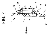
- an installing hole 12 is formed in the molded resin member 10 as illustrated in Figure 2.
- Plural elastic leg portions 13 formed in the deteriorating state checking portion 9 are inserted into the installing hole 12, and nail portions 14 of tips of the leg portions 13 are configured so as to be engaged with edge portions of the installing hole 12.
- the leg portions 13 are elastically bent into the directions indicated by the arrows A, and the nail portions 14 are removed from the edge portions of the installing hole, and further the deteriorating state checking portion 9 is pulled out to the outside as indicated by the arrow B.
- the deteriorating state checking portion 9 may be formed as being exposed to the outside at the upper portion 1A of the upper portion 1A and the lower one 1B. Thereby, the deteriorating state of the product can be more accurately recognized.
- a peripheral equipment such as a gathering machine or a stapler etc. is connected or mounted to the exterior cover 1 in some cases.
- a peripheral equipment such as a gathering machine or a stapler etc.
- FIG 4 in the molded resin member of the exterior cover 1, installing holes 16 for connecting the peripheral equipment 15 (see Figure 3) are formed.
- the peripheral equipment 15 is installed by the desire of an user. Therefore, when the user does not so desire, the peripheral equipment is not connected to the image forming apparatus.
- the installing holes 16 are exposed to the outside, the appearance is reduced. Therefore, conventionally, a deteriorated appearance is prevented by setting a cap to each of the installing holes 16.
- a cap for the installing holes 16, which is necessary when the peripheral equipment 15 is not connected, can be substituted by installing the deteriorating state checking portion 9 in the installing holes 16 or the total number of caps can reduced. Furthermore, an installing hole for installing the deteriorating state checking portion 9 does not have to be formed in other parts of the exterior cover 1. Thereby advantages like lower costs of the image forming apparatus can be obtained.
- the deteriorating state checking portion can be installed also in the peripheral equipment 15, as designated by numeral 109 in Figure 3. Such a structure can be also applied to a case where a product other than the peripheral equipment is connected to the exterior cover 1.
- the installing hole 16 is formed in a molded resin member of a product for installing a product (the peripheral equipment 15 in this embodiment) other than the product (the exterior cover 1 in this embodiment) having the molded resin member, the cost of the product can be decreased by installing the deteriorating state checking portion 9 in the installing hole 16.
- the deteriorating state checking portion 9 is formed as an exclusive element for recognizing the deteriorating state or the deterioration of material properties of the molded resin member.
- the deteriorating state checking portion 9 can be also configured as a member which is originally necessary or functional in a product such as an image forming apparatus etc., for example, as an operation button 17 as illustrated in Figure 1.
- the apparatus when an image forming apparatus which has been used is carried to a recycling dealer, the apparatus is generally roughly handled. For example, the apparatus is put in a place having no roof, in which case the exterior cover 1 is directly exposed to rain water in some cases. In such a case, the deterioration of the exterior cover 1 is promoted. Therefore, in order to reliably recognize that the exterior cover 1 has been exposed to rain water, it is preferable that the exterior cover 1 is configured as described below with respect to another embodiment of the present invention.
- Figure 5 is an enlarged section view from the viewpoint of V - V line in Figure 1
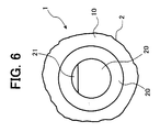
- Figure 6 is a view from the direction indicated by arrow VI in Figure 5.
- a storing case 19 is engaged and fixed with an installing hole 18 which is formed in the molded resin member 10 of the exterior cover 1.
- a capacity or volume changing material M which changes in its capacity or volume by absorbing water, is enclosed.
- the opening of the storing case 19 is closed by a cap 20 except at an upper portion thereof.
- the capacity or volume changing material M in the storing case 19 can be seen (from outside) through a gap 21 in the upper portion of the opening.
- the capacity or volume changing material M is a kind of material that, after having absorbed water, changes in capacity or volume, even when the water is evaporated and removed. After the change, the capacity or volume of the material is maintained.
- the capacity or volume changing material M may be a powder which decreases in capacity or volume by absorbing water.
- the capacity changing material M which changes in capacity by absorbing water, is provided in a molded resin member of a product, and the capacity changing material M is stored in a storing portion where rain water may enter so that the capacity or volume changing material M can been seen from the outside.
- the capacity or volume changing material M is provided at least in the upper portion 1A of an upper portion 1A and a lower portion 1B.
- a storing portion which stores the capacity or volume changing material M may be formed in the molded resin member 10 itself, such that the storing portion is a part of the molded resin member 10.
- the storing case 19 is inserted into the installing hole 18 as illustrated in Figure 5, and an engaging groove 26 formed in an outer circumference portion of the storing case 15 is engaged with the above nail 25 and the storing case 19 is fixed to the molded resin member 10.
- the guides 24 are elastically changed in an enlarging direction as indicated by arrows D in Figure 5, and the nails 25 are removed from the engaging groove 26, and further the storing case 19 is pulled out to the outside as indicated by an arrow sign E in Figure 5.
- the installing hole 16 for installing a product (the peripheral equipment 15 in Figure 3) other than a product having a molded resin member (the exterior cover 1 in Figures 3 and 4) is formed in a molded resin member of the product
- the storing case 19 as illustrated in Figure 5 can be installed to the installing hole 16 when the peripheral equipment 15 is not connected.
- a cap for the installing hole 16 which has been necessary conventionally can be eliminated, or the number of the caps can be decreased.
- the exclusive installing hole for installing the storing case 19 does not have to be formed in the molded resin member.
- the exterior cover of an apparatus such as an image forming apparatus is likely to be exposed to sunlight, rain water or other environmental influences, and therefore the present invention can be applied to such exterior covers of various products.
- the present invention applies to any products which are made of only one molded resin member or to products including a molded resin member as parts thereof, regardless of whether the products are finished products or members thereof.
- the deteriorating state of a molded resin member can be recognized visually in a simple manner.
- a deteriorating state checking portion can be simply exchanged.
- an exclusive installing hole for installing the deteriorating state checking portion does not have to be formed in the molded resin member.
- a storing case for storing the deteriorating checking portion can be simply exchanged.
- an exclusive installing hole for installing the storing case does not have to be formed.
- the embodiments of this invention comprise molded resin member or resin mold members
- the present invention may also be applied to members of other products that change their properties when they are exposed to environmental influences.
- environmental influences as used herein relates to any external influences to which the product might be exposed during its normal lifetime, e.g. in an office environment, during storage at dealers or during transport.
- aging properties as used herein relates to any material properties that change due to the exposure of the product to external influences, e.g. heat, sunlight or wearing during normal use.
Landscapes
- Life Sciences & Earth Sciences (AREA)
- Biodiversity & Conservation Biology (AREA)
- Ecology (AREA)
- Environmental & Geological Engineering (AREA)
- Environmental Sciences (AREA)
- Physics & Mathematics (AREA)
- Health & Medical Sciences (AREA)
- Chemical & Material Sciences (AREA)
- Analytical Chemistry (AREA)
- Biochemistry (AREA)
- General Health & Medical Sciences (AREA)
- General Physics & Mathematics (AREA)
- Immunology (AREA)
- Pathology (AREA)
- Testing Resistance To Weather, Investigating Materials By Mechanical Methods (AREA)
- Electrophotography Configuration And Component (AREA)
- Moulds For Moulding Plastics Or The Like (AREA)
- Injection Moulding Of Plastics Or The Like (AREA)
Applications Claiming Priority (4)
| Application Number | Priority Date | Filing Date | Title |
|---|---|---|---|
| JP2000073439 | 2000-03-16 | ||
| JP2000073439 | 2000-03-16 | ||
| JP2001039475A JP3849971B2 (ja) | 2000-03-16 | 2001-02-16 | 劣化状態確認可能な製品 |
| JP2001039475 | 2001-02-16 |
Publications (2)
| Publication Number | Publication Date |
|---|---|
| EP1134576A2 true EP1134576A2 (de) | 2001-09-19 |
| EP1134576A3 EP1134576A3 (de) | 2001-10-17 |
Family
ID=26587648
Family Applications (1)
| Application Number | Title | Priority Date | Filing Date |
|---|---|---|---|
| EP01106347A Withdrawn EP1134576A3 (de) | 2000-03-16 | 2001-03-16 | Produkt mit Merkmalen zur Feststellung der Verschlechterung von Materialeigenschaften |
Country Status (3)
| Country | Link |
|---|---|
| US (1) | US6644236B2 (de) |
| EP (1) | EP1134576A3 (de) |
| JP (1) | JP3849971B2 (de) |
Families Citing this family (6)
| Publication number | Priority date | Publication date | Assignee | Title |
|---|---|---|---|---|
| JP4095875B2 (ja) * | 2001-10-30 | 2008-06-04 | 株式会社リコー | 現像剤収納容器及び画像形成装置 |
| US7184674B2 (en) * | 2003-09-17 | 2007-02-27 | Ricoh Company, Limited | Detecting device for an image forming apparatus |
| JP2005126110A (ja) * | 2003-10-23 | 2005-05-19 | Tanaka Sangyo Kk | 収納袋 |
| US7110917B2 (en) | 2003-11-14 | 2006-09-19 | Ricoh Company, Ltd. | Abnormality determining method, and abnormality determining apparatus and image forming apparatus using same |
| JP2007171089A (ja) * | 2005-12-26 | 2007-07-05 | Fuji Electric Systems Co Ltd | 成型品の品質検査用試料作成方法 |
| JP2025011699A (ja) | 2023-07-11 | 2025-01-24 | 株式会社リコー | 樹脂成形部品、画像形成装置及び判断方法 |
Family Cites Families (50)
| Publication number | Priority date | Publication date | Assignee | Title |
|---|---|---|---|---|
| US3981958A (en) * | 1973-04-19 | 1976-09-21 | Toyoda Gosei Kabushiki-Kaisha (Toyoda Synthetics Co., Ltd.) | Graft copolymers and process for producing same |
| US4098121A (en) * | 1977-04-08 | 1978-07-04 | Foster-Miller Associates, Inc. | Humidity indicator |
| US4499849A (en) | 1981-04-06 | 1985-02-19 | Ricoh Company, Ltd. | Apparatus for cleaning a recording medium |
| US4547059A (en) | 1981-10-28 | 1985-10-15 | Ricoh Company, Ltd. | Image-transfer-type electrostatic recording apparatus |
| US4571070A (en) | 1983-03-31 | 1986-02-18 | Ricoh Company, Ltd. | Cleaning device for photoconductive element of electrophotographic copier or the like |
| US4655076A (en) * | 1984-01-23 | 1987-04-07 | Raychem Corporation | Moisture measuring apparatus |
| JPS62181312A (ja) * | 1986-02-06 | 1987-08-08 | Mitsubishi Rayon Co Ltd | 耐衝撃性、耐候性および成形性に優れるグラフト共重合体樹脂の製造方法 |
| JPH0548397Y2 (de) | 1989-10-25 | 1993-12-24 | ||
| JP2546851Y2 (ja) | 1990-01-19 | 1997-09-03 | 株式会社リコー | 電子写真装置の現像装置 |
| JPH03215744A (ja) * | 1990-01-22 | 1991-09-20 | Nippon Unicar Co Ltd | 光崩壊性成形物の崩壊レベル判別法 |
| JPH03221986A (ja) | 1990-01-29 | 1991-09-30 | Ricoh Co Ltd | 電子写真装置 |
| FR2683637A1 (fr) * | 1991-11-12 | 1993-05-14 | De Pontbriand Bertrand | Dispositif destine a faciliter la detection de la corrosion dans une installation a fluide. |
| JPH06273326A (ja) * | 1993-03-24 | 1994-09-30 | Densen Sogo Gijutsu Center | 可塑剤および充填剤を含有する合成樹脂成形品の非破壊的劣化診断方法 |
| JP3215744B2 (ja) | 1993-03-25 | 2001-10-09 | 株式会社東芝 | 画像形成装置 |
| JP3312438B2 (ja) | 1993-08-20 | 2002-08-05 | 東洋インキ製造株式会社 | 水検知インジケ−タ− |
| JP3439273B2 (ja) | 1994-01-19 | 2003-08-25 | 株式会社リコー | 電子写真装置 |
| JP3581720B2 (ja) | 1994-01-26 | 2004-10-27 | 株式会社リコー | 現像装置 |
| JPH07306239A (ja) | 1994-05-16 | 1995-11-21 | Hitachi Ltd | 余寿命センサー付き電気製品 |
| JP3403594B2 (ja) | 1995-11-15 | 2003-05-06 | 株式会社リコー | 画像形成装置 |
| US5895843A (en) | 1996-05-15 | 1999-04-20 | The University Of Virginia Patent Foundation | In situ sensor for critical corrosion conditions in a material |
| JPH10171221A (ja) | 1996-10-08 | 1998-06-26 | Ricoh Co Ltd | 画像形成装置及び画像形成方法 |
| JP3537293B2 (ja) | 1996-11-11 | 2004-06-14 | 株式会社リコー | 電子写真装置および感光体ユニット |
| JP3570701B2 (ja) | 1996-11-11 | 2004-09-29 | 株式会社リコー | 画像形成装置 |
| JPH10198110A (ja) | 1996-11-18 | 1998-07-31 | Ricoh Co Ltd | カラー画像形成方法 |
| US5875380A (en) | 1997-02-18 | 1999-02-23 | Ricoh Company, Ltd. | Image forming apparatus eliminating influence of fluctuation in speed of a conveying belt to correction of offset in color registration |
| JPH10240081A (ja) | 1997-02-26 | 1998-09-11 | Ricoh Co Ltd | 電子制御機器 |
| US6112046A (en) | 1997-06-20 | 2000-08-29 | Ricoh Company, Ltd. | Image forming apparatus having recycling of residual toner |
| JPH1184873A (ja) | 1997-07-10 | 1999-03-30 | Ricoh Co Ltd | スクリューポンプ及び該スクリューポンプを用いたトナー移送装置 |
| US5987298A (en) | 1998-02-02 | 1999-11-16 | Ricoh Company, Ltd. | Image forming apparatus including a toner recycling mechanism |
| JPH11258187A (ja) * | 1998-03-12 | 1999-09-24 | Yazaki Corp | 回収可塑剤の品質試験法 |
| EP0965833A1 (de) * | 1998-05-22 | 1999-12-22 | N.V. Kema | Korrosionstester |
| US6163669A (en) | 1998-05-29 | 2000-12-19 | Ricoh Company, Ltd. | Image forming apparatus |
| US6201941B1 (en) | 1998-06-25 | 2001-03-13 | Ricoh Company, Ltd. | Developer container for an image forming apparatus and method of conveying a developer |
| US6122468A (en) | 1998-10-09 | 2000-09-19 | Ricoh Company, Ltd. | Method and apparatus for forming toner images |
| US6295437B1 (en) | 1998-12-28 | 2001-09-25 | Ricoh Company, Ltd. | Apparatus and method for forming an image using a developing device capable of obtaining a high quality image |
| JP2000314688A (ja) * | 1999-04-30 | 2000-11-14 | Mitsubishi Electric Corp | 樹脂成形品とその成形方法並びに検査手法 |
| JP3935666B2 (ja) | 1999-09-30 | 2007-06-27 | 株式会社リコー | ノズル、トナー移送装置および画像形成装置 |
| JP2001166553A (ja) | 1999-12-13 | 2001-06-22 | Ricoh Co Ltd | カラー画像形成装置 |
| JP2001265099A (ja) | 2000-03-17 | 2001-09-28 | Ricoh Co Ltd | 画像形成装置 |
| JP4435385B2 (ja) * | 2000-07-03 | 2010-03-17 | 三菱レイヨン株式会社 | 樹脂被膜が形成された樹脂成形品の耐候性評価方法およびポリカーボネート製成形品 |
| JP4351814B2 (ja) | 2000-07-21 | 2009-10-28 | 株式会社リコー | カラー画像形成装置 |
| JP3958511B2 (ja) | 2000-09-28 | 2007-08-15 | 株式会社リコー | トナー補給装置および画像形成装置 |
| JP2003005608A (ja) | 2000-10-18 | 2003-01-08 | Ricoh Co Ltd | 像担持体上の付着物除去方法およびその方法を用いる画像形成装置 |
| JP3868785B2 (ja) * | 2000-11-10 | 2007-01-17 | 株式会社リコー | 積層型電子写真感光体、画像形成方法、画像形成装置及び画像形成装置用プロセスカートリッジ |
| US6665508B2 (en) * | 2001-01-31 | 2003-12-16 | Ricoh Company, Ltd. | Toner container and image forming apparatus using the same |
| JP2002351287A (ja) * | 2001-03-23 | 2002-12-06 | Ricoh Co Ltd | 作像ユニット及び画像形成装置 |
| DE60238808D1 (de) * | 2001-04-27 | 2011-02-17 | Ricoh Co Ltd | Bilderzeugungsvorrichtung mit verbesserter Tonerzufuhr |
| JP4121333B2 (ja) * | 2001-08-27 | 2008-07-23 | 株式会社リコー | 画像形成装置,プログラム更新方法および記録媒体 |
| JP4083505B2 (ja) * | 2001-08-27 | 2008-04-30 | 株式会社リコー | 画像形成装置,プログラム更新方法および記録媒体 |
| JP4212849B2 (ja) * | 2001-08-31 | 2009-01-21 | 株式会社リコー | 画像形成装置 |
-
2001
- 2001-02-16 JP JP2001039475A patent/JP3849971B2/ja not_active Expired - Fee Related
- 2001-03-16 EP EP01106347A patent/EP1134576A3/de not_active Withdrawn
- 2001-03-16 US US09/809,075 patent/US6644236B2/en not_active Expired - Fee Related
Also Published As
| Publication number | Publication date |
|---|---|
| EP1134576A3 (de) | 2001-10-17 |
| JP2001330554A (ja) | 2001-11-30 |
| US20010036666A1 (en) | 2001-11-01 |
| JP3849971B2 (ja) | 2006-11-22 |
| US6644236B2 (en) | 2003-11-11 |
Similar Documents
| Publication | Publication Date | Title |
|---|---|---|
| US6137564A (en) | Distance measuring device | |
| EP1134576A2 (de) | Produkt mit Merkmalen zur Feststellung der Verschlechterung von Materialeigenschaften | |
| AU718867B2 (en) | Ink tank, production process of ink tank and ink-jet printing apparatus | |
| US7854079B2 (en) | Animal marking tag consisting of a shell comprising two coloured elements | |
| CN101310986A (zh) | 液体盒确定系统和液体盒确定方法 | |
| JPH08500797A (ja) | 遠隔読み取りできるエスコートメモリーを具備した輸送もしくは貯蔵構造を提供する方法及び輸送もしくは貯蔵構造 | |
| CN101021712A (zh) | 用于图像形成装置的可消耗盒及图像形成装置 | |
| US20060038408A1 (en) | Cover | |
| KR101693846B1 (ko) | 차량용 범퍼 백빔 | |
| US20070013654A1 (en) | Image recording apparatus and method for producing image recording apparatus | |
| US5575494A (en) | Trailer coupler guard | |
| US20050062252A1 (en) | Vehicle running board assembly | |
| CN1041910C (zh) | 测头罩存放盒 | |
| EP0922650B1 (de) | Dosendeckel mit integriertem Abstreifer | |
| CA1280786C (en) | Preformed ornamental cap for automotive vehicle | |
| US7995254B2 (en) | Imaging apparatus having scan lid sensing | |
| US10461380B2 (en) | Battery attachment apparatuses | |
| US5668350A (en) | Electric connection box | |
| US5265819A (en) | Photographic film cassette | |
| JP2000261934A (ja) | 電気接続箱 | |
| KR200301717Y1 (ko) | 수도미터기함의 뚜껑 | |
| CN2282723Y (zh) | 录像盒带 | |
| JP2559175Y2 (ja) | 釘打機における釘マガジン | |
| US7121662B2 (en) | Image forming apparatus | |
| JP2000258103A (ja) | 巻尺ケース |
Legal Events
| Date | Code | Title | Description |
|---|---|---|---|
| PUAI | Public reference made under article 153(3) epc to a published international application that has entered the european phase |
Free format text: ORIGINAL CODE: 0009012 |
|
| PUAL | Search report despatched |
Free format text: ORIGINAL CODE: 0009013 |
|
| AK | Designated contracting states |
Kind code of ref document: A2 Designated state(s): AT BE CH CY DE DK ES FI FR GB GR IE IT LI LU MC NL PT SE TR |
|
| AX | Request for extension of the european patent |
Free format text: AL;LT;LV;MK;RO;SI |
|
| AK | Designated contracting states |
Kind code of ref document: A3 Designated state(s): AT BE CH CY DE DK ES FI FR GB GR IE IT LI LU MC NL PT SE TR |
|
| AX | Request for extension of the european patent |
Free format text: AL;LT;LV;MK;RO;SI |
|
| RIC1 | Information provided on ipc code assigned before grant |
Free format text: 7G 01N 17/00 A, 7G 01N 17/04 B |
|
| 17P | Request for examination filed |
Effective date: 20020121 |
|
| AKX | Designation fees paid |
Free format text: AT BE CH CY DE DK ES FI FR GB GR IE IT LI LU MC NL PT SE TR |
|
| 17Q | First examination report despatched |
Effective date: 20060726 |
|
| STAA | Information on the status of an ep patent application or granted ep patent |
Free format text: STATUS: THE APPLICATION IS DEEMED TO BE WITHDRAWN |
|
| 18D | Application deemed to be withdrawn |
Effective date: 20080209 |