EP1134766A2 - Gasisolirete Schaltanlage mit mindestens einem Schalter - Google Patents
Gasisolirete Schaltanlage mit mindestens einem Schalter Download PDFInfo
- Publication number
- EP1134766A2 EP1134766A2 EP01104079A EP01104079A EP1134766A2 EP 1134766 A2 EP1134766 A2 EP 1134766A2 EP 01104079 A EP01104079 A EP 01104079A EP 01104079 A EP01104079 A EP 01104079A EP 1134766 A2 EP1134766 A2 EP 1134766A2
- Authority
- EP
- European Patent Office
- Prior art keywords
- gas
- vessel
- flange
- rubber washer
- insulated switchgear
- Prior art date
- Legal status (The legal status is an assumption and is not a legal conclusion. Google has not performed a legal analysis and makes no representation as to the accuracy of the status listed.)
- Withdrawn
Links
- 230000015572 biosynthetic process Effects 0.000 claims abstract description 18
- 238000007789 sealing Methods 0.000 claims description 13
- 238000000034 method Methods 0.000 claims description 2
- 239000007789 gas Substances 0.000 description 9
- 230000002787 reinforcement Effects 0.000 description 6
- IJGRMHOSHXDMSA-UHFFFAOYSA-N Atomic nitrogen Chemical compound N#N IJGRMHOSHXDMSA-UHFFFAOYSA-N 0.000 description 4
- 239000004033 plastic Substances 0.000 description 3
- 239000000463 material Substances 0.000 description 2
- 229910052757 nitrogen Inorganic materials 0.000 description 2
- 238000005553 drilling Methods 0.000 description 1
- 230000000694 effects Effects 0.000 description 1
- 238000009434 installation Methods 0.000 description 1
- 238000007493 shaping process Methods 0.000 description 1
- 230000001960 triggered effect Effects 0.000 description 1
- 230000037303 wrinkles Effects 0.000 description 1
Images

Classifications
-
- H—ELECTRICITY
- H01—ELECTRIC ELEMENTS
- H01H—ELECTRIC SWITCHES; RELAYS; SELECTORS; EMERGENCY PROTECTIVE DEVICES
- H01H33/00—High-tension or heavy-current switches with arc-extinguishing or arc-preventing means
- H01H33/60—Switches wherein the means for extinguishing or preventing the arc do not include separate means for obtaining or increasing flow of arc-extinguishing fluid
- H01H33/66—Vacuum switches
- H01H33/666—Operating arrangements
-
- H—ELECTRICITY
- H01—ELECTRIC ELEMENTS
- H01H—ELECTRIC SWITCHES; RELAYS; SELECTORS; EMERGENCY PROTECTIVE DEVICES
- H01H9/00—Details of switching devices, not covered by groups H01H1/00 - H01H7/00
- H01H9/02—Bases, casings, or covers
- H01H9/04—Dustproof, splashproof, drip-proof, waterproof, or flameproof casings
- H01H9/047—Dustproof, splashproof, drip-proof, waterproof, or flameproof casings provided with venting means
Definitions
- the invention relates to a gas-insulated switchgear assembly with at least one switch, in particular Vacuum switch, which is arranged in a container filled with insulating gas and its Switch rod via an opening inside the vessel for connection to the Switch drive is brought out gas-tight, whereby for the gas-tight lead-out of the switch rod with this an elastically movable sealing element is gas-tight in connection.
- Such a gas-insulated switchgear concerns the arrangement of a vacuum switch in a container filled with insulating gas and the gastight lead out of the switch rod of the Vacuum switch essentially for example from an opening within the vessel DE 195 17 287 A1.
- the shift rod is brought out gastight via an elastically movable sealing element made of plastic, one of which Edge of the switch rod is connected gas-tight outside the vessel.
- the edge of the plastic sealing element is on one between the wall the vessel and the vacuum switch arranged, the switching rod concentrically at a distance surrounding insulating body connected gastight, the outside of the vessel arranged sealing element is essentially a bellows.
- the invention is based, a gas-insulated switchgear according to the task To provide the preamble of claim 1, in which a gas-tight lead-out of the shift rod from the vessel filled with insulating gas without increasing the installation space of the vessel is achieved, at the same time by a gas-tight lead-out of the shift rod enabling the cost-effective sealing element additionally through the opening spring axial forces to be taken into account of the switch must be avoided.
- the elastically movable sealing element is a rubber washer, the one in the area of the opening inside the vessel with the one hole having flange of an inward formation of the vessel and on the other with the shift rod, forming concentric folds on the free surface of the Rubber disk is connected by pressing gas-tight in such a way that at maximum stroke the Shift rod during a shift the rubber disc within the space after internal shape remains.
- the rubber washer is in the area of its outer circumference on the flange of the inward shaping of the vessel to the outside facing side delimited by a flange that can be inserted into the space of the formation, through which the rubber washer in the area of its outer circumference by pressure elements evenly is deformable.
- the rubber washer is in the area of its inner circumference by two opposing surfaces of the shift rod can be deformed evenly during assembly.
- the shift rod outside of the vessel filled with insulating gas consists of a bolt which is inside the Vessel can be screwed into the threaded bore of a guide.
- This flange stands another flange opposite, through which together with the flange of the guide Rubber washer in the area of its inner circumference via a sleeve placed on the bolt uniformly deformable when the bolt is screwed into the threaded bore of the guide is.
- the rubber washer can also be used in the area its outer circumference to the flange of the inward formation of the vessel and / or in the area of their inner circumference to the flange of the threaded bore Guide preferably glued or vulcanized under pressure.
- the electrical connection which is initially located in the formation of the vacuum switch is closed within the one filled with insulating gas
- the rubber disc is an elastic disc for gas-tight removal of the shift rod the vessel is used, which consists of a material whose properties it also allow that concentric to the shift rod on the free surface of the disc Wrinkles are formed when these are in the area of their outer and inner circumference is pressed.
- the invention also includes a three-pole gas insulated switchgear.
- the invention can be used for any type of switch whose switch rod is led out of the vessel.
- isolators and / or earth electrodes can also be arranged in the vessel filled with insulating gas, the insulating gas being, for example, nitrogen or SF 6 , in addition to the circuit breakers.
- the actuators of the isolator or earth electrode can also be brought out gas-tight via movable sealing elements. Regardless of this, the inventive gas-insulated switchgear is suitable for both high and medium voltage.
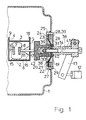
- a vacuum switch 2 is arranged in a vessel 1 of a gas-insulated switchgear, for example filled with nitrogen or SF 6 .
- This consists essentially of the vacuum switching chamber 6 delimited by the insulating cylinder 3 and the reinforcements 4, 5 and the fixed switching contact 7 and the drivable switching contact 8.
- the fixed switching contact 7 with the reinforcement 4 which at the same time has the one electrical connection 9 of the Includes vacuum switch 2
- the drivable switch contact 8 is arranged axially displaceably in the vacuum switching chamber 6.
- the drivable switch contact 8 is connected to a contact rod 11, which is axially displaceable by the switch drive 12 via the lever 13 and the switch rod 14 during a switching operation.
- the reinforcement 5 carries the second electrical connection 18 of the vacuum switch 2.
- the rubber washer 21 is in the region of its outer circumference 22 by means of pressure elements 28 in cooperation with the flange 24 of the formation 25 uniformly deformable, here as pressure elements in the inner wall 29 of the formation 25 screw-in pressure ring 30 is provided.
- This can in the design of the Shape of the rubber washer 21, which it occupies as it moves, that it is not damaged by the edge of the flange 27.
- the rubber disk 21 is pressed in the area of its inner Circumference 31 through two opposing surfaces 34, 35 of the shift rod 14 there is the switching rod 14 outside the vessel 1 from a bolt 36 which is inside the Vessel 1 can be screwed into the threaded bore 37 of a guide 38.
- This has one Flange 39, on which the rubber washer 21 abuts in the region of its inner circumference 31.
- the Flange 39 is opposite another flange 40, through which together with flange 39 the guide 38, the rubber washer 21 in the region of its inner circumference 31 on the Bolt 36 inserted sleeve 41 when screwing the bolt 36 into the threaded bore 37 the guide 38 is pressed and deformed evenly.
Landscapes
- High-Tension Arc-Extinguishing Switches Without Spraying Means (AREA)
- Gas-Insulated Switchgears (AREA)
Abstract
Description
- Fig. 1
- eine Teilansicht einer gasisolierten Schaltanlage mit Vakuumschalter und
- Fig. 2
- eine Teilansicht im Schnitt im Bereich der Herausführung der Schaltstange.
- 1
- Gefäß
- 2
- Vakuumschalter
- 3
- Isolierzylinder
- 4
- Armierungen
- 5
- Armierungen
- 6
- Vakuumschaltkammer
- 7
- feststehender Schaltkontakt
- 8
- antreibbarer Schaltkontakt
- 9
- elektrischer Anschluß
- 10
- Kontaktstange
- 11
- Kontaktstange
- 12
- Schalterantrieb
- 13
- Hebel
- 14
- Schaltstange
- 15
- Kondensatschirm
- 16
- Faltenbalg
- 17
- Kontaktelemente
- 18
- elektrischer Anschluß
- 19
- Öffnung
- 20
- elastisch bewegliches Dichtungselement
- 21
- Gummischeibe
- 22
- äußerer Umfang
- 23
- Bohrung
- 24
- Flansch
- 25
- nach innen gerichtete Ausformung
- 26
- Raum
- 27
- Flansch
- 28
- Druckelemente
- 29
- innere Wandung
- 30
- Druckring
- 31
- innerer Umfang
- 32
- freie Fläche
- 33
- konzentrische Falten
- 34
- Flächen
- 35
- Flächen
- 36
- Bolzen
- 37
- Gewindebohrung
- 38
- Führung
- 39
- Flansch
- 40
- Flansch
- 41
- Hülse
- 42
- abgestufter Isolierkörper
Claims (7)
- Gasisolierte Schaltanlage mit mindestens einem Schalter, insbesondere Vakuumschalter (2), der in einem mit Isoliergas gefüllten Gefäß (1) angeordnet und dessen Schaltstange (14) über eine Öffnung (19) innerhalb des Gefäßes (1) aus diesem zur Verbindung mit dem Schalterantrieb (12) gasdicht herausgeführt ist, wobei zur gasdichten Herausführung der Schaltstange (14) mit dieser ein elastisch bewegliches Dichtungselement (20) gasdicht in Verbindung steht, dadurch gekennzeichnet, daß das elastisch bewegliche Dichtungselement (20) eine Gummischeibe (21) ist, die im Bereich der Öffnung (19) innerhalb des Gefäßes (1) einerseits mit dem eine Bohrung (23) aufweisenden Flansch (24) einer nach innen gerichteten Ausformung (25) des Gefäßes (1) und andererseits mit der Schaltstange (14) unter Bildung von konzentrischen Falten (33) an der freien Fläche (32) der Gummischeibe (21) durch Pressen gasdicht derart in Verbindung steht, daß bei maximalem Hub der Schaltstange (14) bei einem Schaltvorgang die Gummischeibe (21) innerhalb des Raumes (26) der nach innen gerichteten Ausformung (25) verbleibt.
- Gasisolierte Schaltanlage nach Anspruch 1, dadurch gekennzeichnet, daß die Gummischeibe (21) im Bereich ihres äußeren Umfanges (22) auf der dem Flansch (24) der nach innen gerichteten Ausformung (25) des Gefäßes (1) nach außen zugerichteten Seite durch einen in den Raum (26) der Ausformung (25) einsetzbaren Flansch (27) begrenzt ist, durch den die Gummischeibe (21) im Bereich ihres äußeren Umfanges (22) durch Druckelemente (28) gleichmäßig verformbar ist.
- Gasisolierte Schaltanlage nach Anspruch 2, dadurch gekennzeichnet, daß die Gummischeibe (21) im Bereich ihres äußeren Umfanges (22) durch Einschrauben eines Druckringes (30) in die innere Wandung (29) der Ausformung (25) gleichmäßig verformbar ist.
- Gasisolierte Schaltanlage nach Anspruch 2 oder 3, dadurch gekennzeichnet, daß die Gummischeibe (21) im Bereich ihres inneren Umfanges (31) durch zwei sich gegenüberstehende Flächen (34,35) der Schaltstange (14) bei ihrer Montage gleichmäßig verformbar ist.
- Gasisolierte Schaltanlage nach Anspruch 4, dadurch gekennzeichnet, daß die Schaltstange (14) außerhalb des mit Isoliergas gefüllten Gefäßes (1) aus einem Bolzen (36) besteht, der innerhalb des Gefäßes (1) in die Gewindebohrung (37) einer Führung (38) einschraubbar ist, die einen Flansch (39) umfaßt, an dem die Gummischeibe (21) im Bereich ihres inneren Umfanges (31) anliegt, wobei dem Flansch (39) ein weiterer Flansch (40) gegenübersteht, durch den gemeinsam mit dem Flansch (39) die Gummischeibe (21) im Bereich ihres inneren Umfanges (31) über eine auf den Bolzen (36) gesteckte Hülse (41) beim Einschrauben des Bolzens (36) in die Gewindebohrung (37) der Führung (38) gleichmäßig verformbar ist.
- Gasisolierte Schaltanlage nach einem der Ansprüche 1 bis 5, dadurch gekennzeichnet, daß die Gummischeibe (21) im Bereich ihres äußeren Umfanges (22) an den Flansch (24) der nach innen gerichteten Ausformung (25) des Gefäßes (1) und/oder im Bereich ihres inneren Umfanges (31) an den Flansch (39) vorzugsweise unter Druck angeklebt oder anvulkanisiert ist.
- Gasisolierte Schaltanlage nach einem der Ansprüche 1 bis 6, dadurch gekennzeichnet, daß innerhalb des mit Isoliergas gefüllten Gefäßes (1) an die in dieses Gefäß (1) hineingeführte Schaltstange (14) sich eine die Spannungsfestigkeit zwischen der nach innen gerichteten Ausformung (25) des Gefäßes (1) und den Spannungspotential führenden Bauteilen innerhalb des Gefäßes (1) beherrschender, abgestufter Isolierkörper (42) anschließt.
Applications Claiming Priority (2)
| Application Number | Priority Date | Filing Date | Title |
|---|---|---|---|
| DE10013404 | 2000-03-17 | ||
| DE2000113404 DE10013404C1 (de) | 2000-03-17 | 2000-03-17 | Gasisolierte Schaltanlage mit mindestens einem Schalter |
Publications (2)
| Publication Number | Publication Date |
|---|---|
| EP1134766A2 true EP1134766A2 (de) | 2001-09-19 |
| EP1134766A3 EP1134766A3 (de) | 2003-08-13 |
Family
ID=7635371
Family Applications (1)
| Application Number | Title | Priority Date | Filing Date |
|---|---|---|---|
| EP01104079A Withdrawn EP1134766A3 (de) | 2000-03-17 | 2001-02-21 | Gasisolirete Schaltanlage mit mindestens einem Schalter |
Country Status (3)
| Country | Link |
|---|---|
| EP (1) | EP1134766A3 (de) |
| DE (1) | DE10013404C1 (de) |
| NO (1) | NO20011368L (de) |
Cited By (2)
| Publication number | Priority date | Publication date | Assignee | Title |
|---|---|---|---|---|
| CN102714405A (zh) * | 2009-12-14 | 2012-10-03 | 阿尔斯通技术有限公司 | 用于气体绝缘开关设备的连接装置 |
| CN113437573A (zh) * | 2021-06-17 | 2021-09-24 | 北京宇航系统工程研究所 | 一种电连接器深低温零泄漏密封隔离结构 |
Families Citing this family (1)
| Publication number | Priority date | Publication date | Assignee | Title |
|---|---|---|---|---|
| DE102013210194A1 (de) * | 2013-05-31 | 2014-12-04 | Tyco Electronics Amp Gmbh | Anordnung für ein elektrisches Schaltelement mit einer Dichtungsanordnung |
Family Cites Families (5)
| Publication number | Priority date | Publication date | Assignee | Title |
|---|---|---|---|---|
| DE1728095U (de) * | 1956-05-25 | 1956-08-16 | Devag Elek Zitaets Kom Ges Dr | Abdichtung von schaltwelleneinfuehrungen in oelarme schalter. |
| JPH0479117A (ja) * | 1990-07-19 | 1992-03-12 | Fuji Electric Co Ltd | ガス絶縁開閉装置 |
| DE4211154A1 (de) * | 1992-03-31 | 1993-10-07 | Siemens Ag | Gasisolierte Schaltanlage mit einem Vakuumschalter |
| DE19517287A1 (de) * | 1995-05-11 | 1996-11-14 | Abb Patent Gmbh | Elektrische Schaltanlage |
| US5667060A (en) * | 1995-12-26 | 1997-09-16 | Amerace Corporation | Diaphragm seal for a high voltage switch environment |
-
2000
- 2000-03-17 DE DE2000113404 patent/DE10013404C1/de not_active Expired - Fee Related
-
2001
- 2001-02-21 EP EP01104079A patent/EP1134766A3/de not_active Withdrawn
- 2001-03-16 NO NO20011368A patent/NO20011368L/no not_active Application Discontinuation
Cited By (3)
| Publication number | Priority date | Publication date | Assignee | Title |
|---|---|---|---|---|
| CN102714405A (zh) * | 2009-12-14 | 2012-10-03 | 阿尔斯通技术有限公司 | 用于气体绝缘开关设备的连接装置 |
| CN102714405B (zh) * | 2009-12-14 | 2015-07-22 | 阿尔斯通技术有限公司 | 用于气体绝缘开关设备的连接装置 |
| CN113437573A (zh) * | 2021-06-17 | 2021-09-24 | 北京宇航系统工程研究所 | 一种电连接器深低温零泄漏密封隔离结构 |
Also Published As
| Publication number | Publication date |
|---|---|
| EP1134766A3 (de) | 2003-08-13 |
| NO20011368D0 (no) | 2001-03-16 |
| NO20011368L (no) | 2001-09-18 |
| DE10013404C1 (de) | 2001-05-10 |
Similar Documents
| Publication | Publication Date | Title |
|---|---|---|
| DE69624901T2 (de) | Membran-Abdichtung für Hochspannungsschalter-Umgebung | |
| EP2136925B1 (de) | Anordnung zur elektrodynamischen fragmentierung von proben | |
| DE19631323C1 (de) | Druckgasschalter | |
| EP1155429B1 (de) | Vakuumschaltkammer mit ringförmigem isolator | |
| DE19756308C1 (de) | Vakuumschalter, insbesondere für Hochspannung | |
| EP1843376A1 (de) | Schaltkammer eines Hochspannungsschalters mit einem Heizvolumen veränderbarer Grösse | |
| DE19808083C1 (de) | Vakuumschalter | |
| EP4374407A1 (de) | Schaltgerät mit einem faltenbalg | |
| EP4026152B1 (de) | Vakuumschaltvorrichtung für eine schaltung mit haupt- und nebenstrompfad | |
| DE10013404C1 (de) | Gasisolierte Schaltanlage mit mindestens einem Schalter | |
| EP2026431A2 (de) | Schaltermodul für eine elektrische Schaltanlage | |
| DE3044366A1 (de) | Aus mindestens zwei bauteilen bestehendes hochspannungsschaltgeraet | |
| EP1691389A1 (de) | Schaltkammer für einen gasisolierten Hochspannungsschalter | |
| EP0920705B2 (de) | Lastschalter | |
| EP0573690A1 (de) | Druckkontakt | |
| DE69508680T2 (de) | Hochspannungsschalter | |
| BE1014553A3 (de) | Kontaktanordnung fur gleit-und steckkontakte elektrischer gerate und anlagen, insbesondere der elektrischen energietechnick, sowie steuer-und regelungstechnik. | |
| DE2541446C3 (de) | Hoch- bzw. Mittelspannungslastschalter | |
| DE19906156C2 (de) | Vakuumschalter mit mindestens einer Vakuumschaltkammer | |
| EP0734580B1 (de) | Hochspannungs-leistungsschalter mit einer feldelektrode | |
| DE19913059C2 (de) | Hochspannungsleistungsschalter, insbesondere in dreipoliger Ausführung | |
| DE102006056655B4 (de) | Schaltermodul für eine elektrische Schaltanlage | |
| DE69309759T2 (de) | Trägheitskontakt | |
| EP0310538B1 (de) | Elektrischer Hochspannungs-Leistungsschalter | |
| DE19711193C2 (de) | Vakuumschaltkammer |
Legal Events
| Date | Code | Title | Description |
|---|---|---|---|
| PUAI | Public reference made under article 153(3) epc to a published international application that has entered the european phase |
Free format text: ORIGINAL CODE: 0009012 |
|
| AK | Designated contracting states |
Kind code of ref document: A2 Designated state(s): AT BE CH CY DE DK ES FI FR GB GR IE IT LI LU MC NL PT SE TR |
|
| AX | Request for extension of the european patent |
Free format text: AL;LT;LV;MK;RO;SI |
|
| PUAL | Search report despatched |
Free format text: ORIGINAL CODE: 0009013 |
|
| AK | Designated contracting states |
Designated state(s): AT BE CH CY DE DK ES FI FR GB GR IE IT LI LU MC NL PT SE TR |
|
| AX | Request for extension of the european patent |
Extension state: AL LT LV MK RO SI |
|
| 17P | Request for examination filed |
Effective date: 20030705 |
|
| AKX | Designation fees paid |
Designated state(s): AT BE CH CY DE DK ES FI FR GB GR IE IT LI LU MC NL PT SE TR |
|
| STAA | Information on the status of an ep patent application or granted ep patent |
Free format text: STATUS: THE APPLICATION HAS BEEN WITHDRAWN |
|
| 18W | Application withdrawn |
Effective date: 20050615 |