EP1134782A2 - Une lampe à rayons ultraviolets et stérilisateurs et nettoyeurs utilisant ladite lampe - Google Patents
Une lampe à rayons ultraviolets et stérilisateurs et nettoyeurs utilisant ladite lampe Download PDFInfo
- Publication number
- EP1134782A2 EP1134782A2 EP01106054A EP01106054A EP1134782A2 EP 1134782 A2 EP1134782 A2 EP 1134782A2 EP 01106054 A EP01106054 A EP 01106054A EP 01106054 A EP01106054 A EP 01106054A EP 1134782 A2 EP1134782 A2 EP 1134782A2
- Authority
- EP
- European Patent Office
- Prior art keywords
- ultraviolet rays
- ultraviolet ray
- optical filter
- discharge vessel
- ray lamp
- Prior art date
- Legal status (The legal status is an assumption and is not a legal conclusion. Google has not performed a legal analysis and makes no representation as to the accuracy of the status listed.)
- Withdrawn
Links
Images



Classifications
-
- H—ELECTRICITY
- H01—ELECTRIC ELEMENTS
- H01J—ELECTRIC DISCHARGE TUBES OR DISCHARGE LAMPS
- H01J61/00—Gas-discharge or vapour-discharge lamps
- H01J61/02—Details
- H01J61/38—Devices for influencing the colour or wavelength of the light
- H01J61/40—Devices for influencing the colour or wavelength of the light by light filters; by coloured coatings in or on the envelope
-
- H—ELECTRICITY
- H01—ELECTRIC ELEMENTS
- H01J—ELECTRIC DISCHARGE TUBES OR DISCHARGE LAMPS
- H01J61/00—Gas-discharge or vapour-discharge lamps
- H01J61/02—Details
- H01J61/30—Vessels; Containers
-
- C—CHEMISTRY; METALLURGY
- C02—TREATMENT OF WATER, WASTE WATER, SEWAGE, OR SLUDGE
- C02F—TREATMENT OF WATER, WASTE WATER, SEWAGE, OR SLUDGE
- C02F1/00—Treatment of water, waste water, or sewage
- C02F1/30—Treatment of water, waste water, or sewage by irradiation
- C02F1/32—Treatment of water, waste water, or sewage by irradiation with ultraviolet light
- C02F1/325—Irradiation devices or lamp constructions
-
- H—ELECTRICITY
- H01—ELECTRIC ELEMENTS
- H01J—ELECTRIC DISCHARGE TUBES OR DISCHARGE LAMPS
- H01J61/00—Gas-discharge or vapour-discharge lamps
- H01J61/02—Details
- H01J61/30—Vessels; Containers
- H01J61/302—Vessels; Containers characterised by the material of the vessel
-
- C—CHEMISTRY; METALLURGY
- C02—TREATMENT OF WATER, WASTE WATER, SEWAGE, OR SLUDGE
- C02F—TREATMENT OF WATER, WASTE WATER, SEWAGE, OR SLUDGE
- C02F1/00—Treatment of water, waste water, or sewage
- C02F1/72—Treatment of water, waste water, or sewage by oxidation
- C02F1/725—Treatment of water, waste water, or sewage by oxidation by catalytic oxidation
-
- C—CHEMISTRY; METALLURGY
- C02—TREATMENT OF WATER, WASTE WATER, SEWAGE, OR SLUDGE
- C02F—TREATMENT OF WATER, WASTE WATER, SEWAGE, OR SLUDGE
- C02F2201/00—Apparatus for treatment of water, waste water or sewage
- C02F2201/32—Details relating to UV-irradiation devices
- C02F2201/326—Lamp control systems
-
- F—MECHANICAL ENGINEERING; LIGHTING; HEATING; WEAPONS; BLASTING
- F24—HEATING; RANGES; VENTILATING
- F24F—AIR-CONDITIONING; AIR-HUMIDIFICATION; VENTILATION; USE OF AIR CURRENTS FOR SCREENING
- F24F8/00—Treatment, e.g. purification, of air supplied to human living or working spaces otherwise than by heating, cooling, humidifying or drying
- F24F8/20—Treatment, e.g. purification, of air supplied to human living or working spaces otherwise than by heating, cooling, humidifying or drying by sterilisation
- F24F8/22—Treatment, e.g. purification, of air supplied to human living or working spaces otherwise than by heating, cooling, humidifying or drying by sterilisation using UV light
-
- H—ELECTRICITY
- H01—ELECTRIC ELEMENTS
- H01J—ELECTRIC DISCHARGE TUBES OR DISCHARGE LAMPS
- H01J61/00—Gas-discharge or vapour-discharge lamps
- H01J61/70—Lamps with low-pressure unconstricted discharge having a cold pressure < 400 Torr
- H01J61/72—Lamps with low-pressure unconstricted discharge having a cold pressure < 400 Torr having a main light-emitting filling of easily vaporisable metal vapour, e.g. mercury
-
- H—ELECTRICITY
- H01—ELECTRIC ELEMENTS
- H01J—ELECTRIC DISCHARGE TUBES OR DISCHARGE LAMPS
- H01J65/00—Lamps without any electrode inside the vessel; Lamps with at least one main electrode outside the vessel
- H01J65/04—Lamps in which a gas filling is excited to luminesce by an external electromagnetic field or by external corpuscular radiation, e.g. for indicating plasma display panels
- H01J65/042—Lamps in which a gas filling is excited to luminesce by an external electromagnetic field or by external corpuscular radiation, e.g. for indicating plasma display panels by an external electromagnetic field
- H01J65/046—Lamps in which a gas filling is excited to luminesce by an external electromagnetic field or by external corpuscular radiation, e.g. for indicating plasma display panels by an external electromagnetic field the field being produced by using capacitive means around the vessel
Definitions
- the present inventions relate in general to ultraviolet ray lamps and to sterilizers and cleaners using ultraviolet light. More specifically, the inventions described herein feature ultraviolet ray lamps having a predetermined spectrum of wavelengths.
- an apparatus for treating fluid such as a sterilizer, or an air cleaner utilizes an ultraviolet ray lamp. It is desired that such apparatus effectively remove or decompose harmful ingredients.
- an apparatus for treating water includes a water tank for collecting water including harmful ingredients.
- An ultraviolet ray lamp is arranged in proximity to the water and_irradiates_ultraviolet rays into the water in order to remove or decompose harmful contaminants.
- An ultraviolet ray lamp of this type comprises an ultraviolet rays-transmitting glass bulb made of soft glass, or quartz glass.
- the transmittance of quartz glass is higher than that of soft glass, so quartz glass is usually used for the glass bulb.
- An ultraviolet ray lamp having quartz glass bulb can irradiate ultraviolet rays having wavelengths of 254nm and 185nm.
- Ultraviolet rays of 185nm decompose molecular oxygen (O 2 ) of air into atomic oxygen (O). Then, atomic oxygen (O) bonds with molecular oxygen (O 2 ), to form ozone.
- Ozone is a sterilizer, however it is harmful to our health at a strong concentration.
- the concentration of ozone is preferably maintained at 0.1ppm or less to minimize health risk. For example, in case of a sterilizer or an air cleaner using an ultraviolet ray lamp, if the apparatus is set up indoors, ozone generated causes a bad smell. It is also harmful to health to have too strong a concentration of ozone.
- Japanese Laid Open Patent Application HEI 10-69886 discloses an arrangement for minimizing the production of ozone. It includes a quartz glass bulb (hereafter referred to as 'ozone-less quartz glass') containing titanium oxide (TiO 2 ), or cerium oxide (CeO 2 ) and a zirconium oxide (ZrO 2 ) film formed on the inner surface of the quartz glass bulb.
- the ozone-less quartz glass can transmit ultraviolet rays of 254nm that are generated by mercury (Hg), but do not easily transmit ultraviolet rays of 185nm that are generated by mercury (Hg).
- the ozone-less quartz glass has a characteristic of absorbing ultraviolet rays of 220nm or less because, for example, titanium oxide (TiO 2 ) contained in the quartz glass bulb, absorbs ultraviolet rays of the comparatively short wavelength.
- titanium oxide (TiO 2 ) contained in the quartz glass bulb, absorbs ultraviolet rays of the comparatively short wavelength.
- titanium oxide (TiO 2 ) starts to absorb ultraviolet rays of the comparatively long wavelength. Therefore, the quantity of the titanium oxide (TiO 2 ) is exactly controlled to ten PPM or less.
- ultraviolet rays of 185nm are absorbed at the inner surface of the glass bulb, so that its ultraviolet rays do not reach the outer surface of the glass bulb.
- ozone-less quartz glass tends to shrink when it is bombarded with ultraviolet rays of 185nm.
- the glass bulb shrinks at its inner surface, but does not shrink at its outer surface. Therefore, a strain occurs on the surface of the glass bulb. If there is a flaw on the outer surface of the bulb when it is manufactured, the bulb may crack due to the strain when it is operated. Because the zirconium oxide (ZrO 2 ) film absorbs ultraviolet rays of 185nm, the ozone-less quartz glass bulb does not strain easily and is less likely to crack.
- the above-described ultraviolet ray lamp cuts off most of the ultraviolet rays of 185nm.
- the ultraviolet ray lamp which does not easily crack, is not very efficient at producing ozone generated by ultraviolet rays of 185nm in order to sterilize.
- an ultraviolet ray lamp comprises a discharge vessel made of quartz glass having a filling gas therein.
- a pair of electrodes is able to generate a discharge in the discharge vessel.
- a device for generating ultraviolet rays comprises an ultraviolet ray lamp generating ultraviolet rays including short and long wavelength, having a discharge vessel made of quartz glass.
- An enclosure accommodates the discharge vessel, transmitting at least ultraviolet ray of short wavelength.
- a sterilizer comprises the device for generating ultraviolet rays having the ultraviolet ray lamp.
- a holder supports the ultraviolet ray lamp.
- a body fixes the holder, and accommodates the ultraviolet ray lamp.
- a sterilizer comprises the ultraviolet ray lamp.
- a holder supports the ultraviolet ray lamp.
- a body fixes the holder, and accommodates the ultraviolet ray lamp.
- an apparatus for treating water comprises the device for generating ultraviolet rays having an ultraviolet ray lamp.
- a holder supports the ultraviolet ray lamp.
- a water tank fixes the holder, and accommodates the ultraviolet ray lamp.
- a blower supplies air to the tank.
- an air cleaner comprises an ultraviolet ray lamp housed in a case.
- a blower causes airflow through an intake of the case, past the lamp and out of an exhaust.
- FIGURES 1 to 3 A first exemplary embodiment of the invention will be explained referring to FIGURES 1 to 3.
- FIGURE 1 shows a front view of an ultraviolet ray lamp according to the first embodiment.
- FIGURE 2 shows a side view of the ultraviolet ray lamp shown in FIGURE 1.
- FIGURE 3 shows an enlarged longitudinal section of the ultraviolet ray lamp shown in FIGURE 1.
- the ultraviolet ray lamp comprises a U-shaped discharge vessel 1 made of transparent quartz glass.
- Vessel 1 has a discharge space portion 1a having two straight portion 1a1, 1a1, and curved portion 1a2.
- Each of seals 1b, 1b is formed into flat shape at the ends of the discharge space portion 1a.
- the flat seals 1b face in parallel and are perpendicularly arranged to a plane including the discharge vessel 1.
- An exhaust portion 1c is formed in straight portion 1a1 about 50mm from the tip of curved portion 1a2.
- discharge vessel 1 has a length of 152mm, and a width of 18mm.
- the discharge space portion 1a has a 6mm outer diameter, and a 300mm inner space length.
- the quartz glass substantially transmits the ultraviolet rays of the wavelength of 254nm and 185nm. This is because the quartz glass does not contain substantial quantities of titanium oxide (TiO 2 ), and cerium oxide (CeO 2 ).
- the discharge vessel may further comprise a film on the inner surface thereof, which prevents mercury (Hg) of the vessel from permeating the quartz glass.
- the presence of the film maintains the quantity of mercury (Hg), so that the discharge lamp maintains good light levels throughout its entire life.
- the film may be made of aluminum oxide (Al 2 O 3 ), titanium oxide (TiO 2 ), or rare earth metal, e.g., yttrium oxide.
- Electrodes 2 of this embodiment are of the cold cathode type.
- Each electrode 2 has a coil 2a made of tungsten, an emitter (not shown), and an electrode rod 2b made of tungsten, and is disposed in the discharge vessel 1.
- a first end of each of electrodes 2 is respectively embedded in its corresponding seal 1b and is connected to a corresponding molybdenum foil 3, embedded in seals 1b.
- Each molybdenum foil 3 is also connected to a corresponding conductive wire 4.
- a pair of the electrodes may be arranged to the outer surface of the discharge vessel along the vessel.
- this embodiment describes a vessel arrangement in which there are two electrodes within the discharge vessel, other arrangements are possible.
- one electrode can be formed as described above and be positioned within the discharge vessel and the other electrode may be arranged outside of the discharge vessel, such as on its outer surface.
- the outer electrode may be made of a conductive foil, mesh, coil, thin film, or metal oxide film made of ITO including indium oxide (In 2 O 3 ), and tin oxide (SnO 2 ).
- the discharge vessel 1 has a filling gas, which contains mercury (Hg), and rare gases including argon (Ar) and neon (Ne).
- the filling gas may contain components that cause there to be generated ultraviolet rays of 185nm and 254nm.
- An optical filter 5, shown in the Figures as being on the outer surface of vessel 1, is made of zirconium oxide (ZrO 2 ). This filter substantially cuts off ultraviolet rays of short wavelength and allows passage of ultraviolet rays of long wavelength.
- the filter material is formed on about 85% of the surface area of discharge vessel 1.
- the optical filter 5 may be mainly made of metal oxide having an energy band gap in the range of 4.5 to 6.7eV. When the metal oxide has a band gap in this range, the metal oxide can cut off ultraviolet rays of 185nm or less, and allow those of 254nm or more to pass.
- the metal oxide may further comprise another metal oxide, e.g., silicon oxide (SiO 2 ), or aluminum oxide (Al 2 O 3 ).
- Zirconium oxide (ZrO 2 ) is suitable for the optical filter, as zirconium oxide (ZrO 2 ) has a band gap in the range of 4.5 to 6.7eV, and does not change chemically.
- the amount of area, e.g., above 85%, of the optical filter 5 correlates with the amount of ozone created by the wavelength of 185nm inducing an oxygen reaction. That is, ozone increases in inverse proportion to the area covered by the optical filter 5.
- the ozone can sterilize the air or a liquid.
- the optical filer may be formed on at least one surface of the discharge vessel.
- the optical filter may prevent the vessel from cracking because the filter can cover a flaw, if it has been formed on the surface of the bulb.
- impurities generating from the optical filer during the lamp operation, can easily be released to the outside.
- quartz glass tends to reduce its transparency, when it is touched by hand.
- quartz glass of the discharge vessel is constructed with the optical filer, the transparency of the discharge vessel does not decrease.
- the optical filter can be constructed and arranged in various ways.
- One way to make the filter follows: (1) dipping the discharge vessel 1 into a bath of water containing zirconium oxide having particles of 30nm average diameter and a surface active agent to form a zirconium oxide layer. (2) baking the discharge vessel having the zirconium oxide layer at the temperature of 450 degrees centigrade in the atmosphere.
- the optical filter of zirconium oxide (ZrO 2 ) is constructed and arranged to further include silicon oxide (SiO 2 ), and aluminum oxide (Al 2 O 3 ), the optical filter can be formed at lower temperature of 200 to 300 degrees centigrade. This optical filter becomes strong and has improved optical performance.
- a lamp base 6 made of polymers containing fluorine is fixed in the seals 1b with a silicone adhesive agent.
- Each of lead wires 7 connecting to a respective conductive wire 4 extend from the lamp base 6.
- the other ends of lead wires 7 are coupled to respective terminals 8.
- Terminals 8 are connected to a ballast (not shown), e.g., an inverter generating a high frequency power.
- the lamp base 6 has a flange 6a so that a fixing ring 13 (shown in FIGURE 5) can hold the lamp.
- the ultraviolet ray lamp including the lamp base 6 is about 190mm length fully assembled. Of course that is true for the specific exemplary embodiment described. Many other structural arrangements are possible.
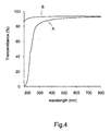
- FIGURE 4 is a graph of transmittance (vertical axis) as a function of wavelength (horizontal axis) of the ultraviolet ray lamp.
- the vertical axis is calibrated in transmittance (%) as a function of wavelength.
- the horizontal axis is calibrated in wavelength (nm) of the ultraviolet ray lamp.
- Line A represents the transmittance of part of the discharge vessel 1 having the optical filter 5.
- Line B represents the transmittance of part of the discharge vessel 1 not being coated the optical filter 5. According to the line A, the optical filter 5 can substantially cut off ultraviolet rays of 185nm and transmit almost ultraviolet rays of 254nm.
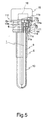
- FIGURE 5 is a side view, partly in section, of a device for generating ultraviolet rays according to the present invention.
- the same reference numerals refer to like or similar parts to those already described and therefore detailed explanation of those parts will not be provided.
- the device for generating ultraviolet rays is provided with an enclosure 10 accommodating a discharge vessel 1.
- An optical filter 5 is formed not on the discharge vessel 1 (as in the first embodiment), but rather on the enclosure 10.
- Other elements of an ultraviolet ray lamp 9 are the same as the first embodiment.
- a lamp base 6 is inserted into an opening 10a of the enclosure 10 made of transparent quartz glass, and the enclosure 10 is air-tightly sealed with a silicone adhesive agent (not shown).
- the enclosure may define some holes in order to allow a fluid, e.g., liquid or air to pass.
- the optical filter 5 made of zirconium oxide, which can substantially cut off ultraviolet rays of short wavelength and transmit ultraviolet rays of long wavelength, is formed on the upper half of enclosure 10.
- the optical filer may be formed at least on one surface of the enclosure.
- Enclosure 10 is steeped in the liquid to be sterilized.
- Ultraviolet rays are generated and pass through enclosure 10 steeped in the liquid. These ultraviolet rays have wavelengths of 185nm and 254nm because optical filter 5 is not formed on the lower half of the enclosure.
- the rays of wavelength 185nm cause oxygen in the liquid to react to create ozone in the liquid.
- the resulting ozone and the ultraviolet rays of 254nm effectively sterilize the liquid.
- the area of enclosure 10 covered by the optical filter 5 can control the amount of ozone generated by controlling the amount of 185 nm ultraviolet radiation. Due to the effectiveness of the optical filter 5, and if the surface level of the liquid is properly selected, this arrangement can prevent the production of ozone in the air.
- a holder 11 made of aluminum die-casting includes a lower opening 11a in order to allow the passage of envelope 10, and an upper opening 11b having a screw groove for accommodating fixing ring 13.
- the inner surface between the openings 11a and 11b is constructed and arranged as an inclined plane 11c.
- a groove 11d and fixing flange 11e are respectively formed on the middle outer surface of the holder 11.
- the upper opening 11b also has a supporting flange 11f on the outer side thereof.
- a ring-shaped seal 12 having a wedge-shaped section is arranged on the inclined plane 11c.
- the fixing ring 13 is provided with a holding portion 13a on its inner surface, and a screw 13b on its outer surface.
- the fixing ring 13 is inserted along the outer surface of the lamp base 6 so as to touch the holding portion 13a to the flange 6a, before the opening 10a of the enclosure 10 is fixed to the lamp base 6 with the silicone adhesive agent.
- the holding portion 13a of the fixing ring 13 is arranged between the flange 6a and the end of the enclosure 10, so that the fixing ring 13 is fixed.
- the ring-shaped sealing 12 is arranged on the inclined plane 11c of the holder 11, the holder 11 is inserted along the surface of the enclosure 10.
- the screw 13b of the fixing ring 13 is applied to the screw groove of upper opening 11b. Accordingly, the ring-shaped seal 12 is tightly put between the fixing ring 13, holder 11, and a part of the enclosure 10.
- An O-shaped ring 14 put into the groove 11d can seal, when the device for generating ultraviolet rays is applied to another apparatus.
- a cover 15 which is fixed to the supporting flange 11f by some screws, accommodates a ballast 16, including a high frequency inverter, and other electrical elements.
- FIGURE 6 shows a side view, partly in section, of a sterilizer according to the present invention.
- the sterilizer comprises a body 21 and the device for generating ultraviolet rays 22.
- Water 23 including bacteria is to be sterilized.
- the body 21 filled with water 23, e.g., water, has a cylinder-shaped opening 21a, which fixes the device 22 by inserting the holder 11 having the O-shaped ring 14 of the device 22 into the cylinder-shaped opening 21a. Accordingly, ultraviolet rays generating from the device irradiate fluid, so that the water becomes sterilized.
- the body 21 of the sterilizer may further comprise a material for reflecting ultraviolet rays on the inner surface thereof, so that the reflected ultraviolet rays also can sterilize fluid.
- the body 21 may be made of a material, which can effectively reflect ultraviolet rays.
- the sterilizer may further comprise a photocatalytic member.
- the sterilizer described in this embodiment may utilize the ultraviolet ray lamp of the first embodiment or some other ultraviolet lamp.
- the ultraviolet ray lamp may have a holder to be supported at a body. The body accommodates the ultraviolet ray lamp.
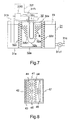
- FIGURE 7 is a section, schematically shown, of an apparatus for treating water according to the present invention.
- the apparatus for treating water 33 comprises a fluid tank 31, and a device 32 for treating the fluid.
- the apparatus can decompose toxic substances, e.g., tri-chloro-ethylene, poly-chloro-di-benzo-para-di-oxin (PCDD), or choloroform, remove color from an organic-coloring matter, or sterilize.
- toxic substances e.g., tri-chloro-ethylene, poly-chloro-di-benzo-para-di-oxin (PCDD), or choloroform
- Tank 31 has a body 31a having an opening (not shown) in order to fix the device 32, a supplying pipe 31b, and a draining pipe 31c connected to tank 31 via a valve 31c1. Fluid is supplied to tank 31 via the supplying pipe 31b, and drained via the draining pipe 31c after the device 32 sterilizes fluid 33.
- the treating device 32 comprises an ultraviolet ray lamp 32a, a cylindrical enclosure 32b, a holder 32c, photocatalytic filters 32d, a pair of photocatalytic plates 32e, 32e, and a blower 32f.
- the ultraviolet ray lamp 32a has a discharge vessel that is not coated with an optical filter as shown in FIGURE 5.
- the enclosure 32b made of quartz glass, which defines plural holes 32b1 for passing fluid, accommodates the ultraviolet ray lamp 32a.
- Enclosure 32b forms an optical filter, which can substantially cut off ultraviolet rays of short wavelength, e.g., 185nm and transmit ultraviolet rays of long wavelength, e.g., 254nm. For this purpose, it is made with a sufficient amount of zirconium oxide.
- the holder 32c supports the ultraviolet ray lamp 32a, and the enclosure 32b together.
- Photocatalytic filters 32d which have a photocatalytic layer made of titanium oxide, are arranged on both sides of the ultraviolet ray lamp 32a so as to be passed through water 33 being supplied via the supplying pipe 31b.
- Photocatalytic plates 32e which forms a photocatalytic layer made of titanium oxide on the inner surface thereof, are arranged at the upper and lower sides of tank body 31a.
- the upper side photocatalytic plate 32e supports the holder 32c of the ultraviolet ray lamp 32a.
- the blower 32f comprises a pump 32f2, and a supplying pipe 32f1 connected to the enclosure 32b. Air is generated by pump 32f2 and is supplied to the enclosure 32b via the supplying pipe 32f1 as represented by the arrow in FIGURE 7.
- the ultraviolet ray lamp 32a irradiates ultraviolet rays of wavelength of 254nm and 185nm.
- the wavelength of 254nm sterilizes water 33 and also activates the photocatalytic materials of the photocatalytic filters 32d, and the photocatalytic plates 32e.
- the photocatalytic materials remove or decompose harmful-organic ingredients of fluid 33.
- the wavelength of 185nm reacts on oxygen, which is supplied by air supplied by pump 32f2, so that ozone is generated in the enclosure 10.
- Ozone and air indicated as B flow into water 33 via holes 32b1, so that ozone removes or decomposes harmful-organic ingredients of fluid 33.
- ultraviolet rays, ozone, and the photocatalytic material can decompose water sufficiently and efficiently.
- FIGURE 8 is a schematic section of an air cleaner according to the present invention.
- the air cleaner includes ultraviolet ray lamps 45, photocatalytic member 44, e.g., photocatalytic filters, a blower 46 making an airflow, and a case 41 including an intake 42 and an exhaust 47.
- a filter 43 is also arranged between the intake 42 and the photocatalytic filter 44, and removes dust from the air.
- the ultraviolet ray lamps 45 having an optical filter on a discharge vessel, can be the same as described with respect to the first embodiment.
- the optical filter made of zirconium oxide, which can substantially cut off ultraviolet rays of short wavelength and transmit ultraviolet rays of long wavelength, is formed on the surface area of 85% of the discharge vessel. The area, e.g., above 85%, of the optical filter can easily control the quantity of ozone created by the wavelength of 185nm reacting on oxygen.
- Photocatalytic filters 44 which comprises a substance such as filter and photocatalytic material made of titanium oxide on the surface of the filter, are arranged to both sides of the ultraviolet ray lamps 45.
- the photocatalytic filter 44 includes many fibers and photocatalytic materials adhered to the fibers, air including dust can contact many photocatalytic materials. Therefore, the photocatalytic materials remove or decompose effectively harmful-organic ingredients of air.
- the photocatalytic member may be formed from a suitable photocatalytic material.
- the substance having the photocatalytic material is made of an inorganic material, e.g., a glass, a metal, or a ceramics, which is not easily decomposed by the photocatalytic material.
- the photocatalytic material may be formed into a spherical shape, so that the organic substance can contact to the photocatalytic material at small area. Accordingly, the organic substance is hardly decomposed by the photocatalytic material at the contacting area.
- the photocatalytic material may be one or more selected from a group of titanium oxide (TiO 2 ), tungsten oxide (WO 3 ), lanthanum rhodium phosphorus (LaRhP 3 ), iron titanium oxide (FeTiO 3 ), iron oxide (Fe 2 O 3 ), cadmium di-iron oxide (CdFe 2 O 4 ), strontium titanium oxide (SrTiO 3 ), cadmium selenium (CdSe), gallium arsenic (GaAs), gallium phosphide (GaP), ruthenium oxide (RuO 2 ), zinc oxide (ZnO), cadmium sulfide (CdS), molybdenum sulfide (MoS 3 ) or (MoS 2 ), lanthanum rhodium oxide (LaRhO 3 ), cadmium iron oxide (CdFeO 3 ), bismuth oxide (Bi 2 O 3 ), indium oxide (In 2
- the absolute reduction-oxidation potential of the band gap of photocatalytic material which is titanium oxide (TiO 2 ), tungsten oxide (WO 3 ), strontium titanium oxide (SrTiO 3 ), iron oxide (Fe 2 O 3 ), cadmium sulfide (CdS), molybdenum sulfide (MoS 3 ) or (MoS 2 ), bismuth oxide (Bi 2 O 3 ), indium oxide (In 2 O 3 ), or cadmium oxide (CdO), is larger than that of the conduction band. Therefore, these photocatalytic materials can effectively decompose the organic compound, so that can remove odor ingredients, pollution, or bacteria.
- Titanium oxide (TiO 2 ) has crystal forms of anatase and rutile structure.
- the anatase structure of titanium oxide (TiO 2 ) has more effective photocatalysis than the rutile structure.
- the ultraviolet ray lamps 45 irradiate ultraviolet rays of wavelength of 254nm and 185nm.
- the wavelength of 254nm sterilizes air and also activates the photocatalytic materials of the photocatalytic filters 44.
- the photocatalytic materials remove or decompose harmful-organic ingredients of air.
- the wavelength of 185nm irradiates through a discharge vessel not being coated the optical filter.
- the wavelength of 185nm reacts on oxygen, which is supplied by air from the blower 46, so that ozone occurs. Ozone also removes or decomposes harmful-organic ingredients of air.
- the air cleaner can clean air by means of removing or decomposing including bacteria, odor, or pollution.
- ultraviolet rays, ozone, and the photocatalytic material can decompose air sufficiently.
Landscapes
- Engineering & Computer Science (AREA)
- Chemical & Material Sciences (AREA)
- Organic Chemistry (AREA)
- Hydrology & Water Resources (AREA)
- Life Sciences & Earth Sciences (AREA)
- Environmental & Geological Engineering (AREA)
- Water Supply & Treatment (AREA)
- Toxicology (AREA)
- Health & Medical Sciences (AREA)
- Combustion & Propulsion (AREA)
- Mechanical Engineering (AREA)
- General Engineering & Computer Science (AREA)
- Physical Water Treatments (AREA)
- Disinfection, Sterilisation Or Deodorisation Of Air (AREA)
- Apparatus For Disinfection Or Sterilisation (AREA)
- Vessels And Coating Films For Discharge Lamps (AREA)
Applications Claiming Priority (4)
| Application Number | Priority Date | Filing Date | Title |
|---|---|---|---|
| JP2000071247 | 2000-03-14 | ||
| JP2000071247 | 2000-03-14 | ||
| JP2000397228A JP2001332216A (ja) | 2000-03-14 | 2000-12-27 | 放電ランプ、光照射装置、殺菌装置、液体処理装置および空気清浄装置 |
| JP2000397228 | 2000-12-27 |
Publications (2)
| Publication Number | Publication Date |
|---|---|
| EP1134782A2 true EP1134782A2 (fr) | 2001-09-19 |
| EP1134782A3 EP1134782A3 (fr) | 2004-09-08 |
Family
ID=26587490
Family Applications (1)
| Application Number | Title | Priority Date | Filing Date |
|---|---|---|---|
| EP20010106054 Withdrawn EP1134782A3 (fr) | 2000-03-14 | 2001-03-12 | Une lampe à rayons ultraviolets et stérilisateurs et nettoyeurs utilisant ladite lampe |
Country Status (4)
| Country | Link |
|---|---|
| US (1) | US6861787B2 (fr) |
| EP (1) | EP1134782A3 (fr) |
| JP (1) | JP2001332216A (fr) |
| KR (1) | KR100392387B1 (fr) |
Cited By (11)
| Publication number | Priority date | Publication date | Assignee | Title |
|---|---|---|---|---|
| WO2003061717A1 (fr) * | 2002-01-16 | 2003-07-31 | Vent Master (Europe) Limited | Dispositif et procede de ventilation a lampes a u.v. |
| US6761203B1 (en) | 2003-03-31 | 2004-07-13 | Tai-Long Huang | Balanced window blind having a spring motor for concealed pull cords thereof |
| EP1306883A4 (fr) * | 2000-07-07 | 2006-08-30 | Photoscience Japan Corp | Appareil de traitement par les uv |
| EP2211371A3 (fr) * | 2008-12-23 | 2011-09-21 | uv-technik Speziallampen GmbH | Lampe à décharge, dispositif de nettoyage d'un gaz contenant de l'oxygène et installation de ventilation |
| CN102354653A (zh) * | 2011-07-11 | 2012-02-15 | 芦建锋 | 提高套管式紫外灯185nm紫外线透过率的方法及灯管 |
| EP2060177A3 (fr) * | 2007-11-19 | 2012-05-02 | General Electric Company | Source lumineuse améliorée pour attraction d'insectes |
| EP2225179A4 (fr) * | 2007-12-05 | 2014-01-22 | Wallenius Water Ab | Dispositif de traitement de fluides |
| WO2014194404A1 (fr) * | 2013-06-07 | 2014-12-11 | Trojan Technologies | Système de détermination de dose uv dans un système de réacteur |
| RU186758U1 (ru) * | 2018-07-30 | 2019-01-31 | Вадим Валерьевич Хмельницкий | Установка обеззараживания поверхности труднодоступных участков вертикальных вентиляционных шахт систем вентиляции и кондиционирования воздуха |
| CN109399754A (zh) * | 2018-12-28 | 2019-03-01 | 深圳合核环境科技有限公司 | 一种光解系统及方法 |
| CN111920999A (zh) * | 2020-09-28 | 2020-11-13 | 武汉光谷航天三江激光产业技术研究院有限公司 | 一种基于紫外激光与TiO2光催化的空气净化装置及方法 |
Families Citing this family (40)
| Publication number | Priority date | Publication date | Assignee | Title |
|---|---|---|---|---|
| DE19941531A1 (de) * | 1999-09-01 | 2001-03-08 | Philips Corp Intellectual Pty | Farbige Signalleuchte mit eisenoxidpigmentbeschichteter Lampe |
| JP2003017005A (ja) * | 2001-06-27 | 2003-01-17 | Harison Toshiba Lighting Corp | 低圧放電ランプ |
| WO2003030957A1 (fr) * | 2001-10-11 | 2003-04-17 | Straumann Holding Ag | Implants osteophiles |
| JP2003123699A (ja) * | 2001-10-19 | 2003-04-25 | Manabu Nitoda | 光触媒作用を活性化する方法及び光触媒放電管、並びにこの原理を用いた製品 |
| JP3390429B1 (ja) | 2002-09-18 | 2003-03-24 | サカエ理研工業株式会社 | 空気清浄フィルタ装置 |
| CN100391858C (zh) * | 2002-11-27 | 2008-06-04 | 株式会社日本光电科技 | 紫外线液体处理装置和处理方法 |
| KR100723124B1 (ko) * | 2002-11-28 | 2007-05-30 | 가부시키가이샤 니혼포토사이언스 | 자외선에 의한 액체 처리 장치 및 방법 |
| US6828720B2 (en) * | 2002-12-18 | 2004-12-07 | Osram Sylvania Inc. | Compact fluorescent sun-tanning lamp |
| US7255831B2 (en) * | 2003-05-30 | 2007-08-14 | Carrier Corporation | Tungsten oxide/titanium dioxide photocatalyst for improving indoor air quality |
| DE102004048005A1 (de) * | 2004-10-01 | 2006-04-13 | Dr. Hönle AG | Gasentladungslampe, System und Verfahren zum Härten von durch UV-Licht härtbare Materialien sowie durch UV-Licht gehärtetes Material |
| US20070035249A1 (en) * | 2005-08-10 | 2007-02-15 | Geza Cseh | Lamp with inner capsule |
| CN1977978B (zh) * | 2005-12-01 | 2011-07-06 | 福建新大陆环保科技有限公司 | 一种开放式水渠辐射消毒系统 |
| US20070207066A1 (en) * | 2006-03-02 | 2007-09-06 | Guardian Technologies Llc | Air sterilization device and uses thereof |
| KR100832398B1 (ko) * | 2007-07-20 | 2008-05-26 | 남승엽 | 무전극 지르코늄 자외선램프와 이를 이용한 액상 살균장치 |
| JP2011003325A (ja) * | 2009-06-17 | 2011-01-06 | Autec:Kk | 照明機能を有する紫外線発生ランプ |
| JP2011023253A (ja) * | 2009-07-17 | 2011-02-03 | Iwasaki Electric Co Ltd | 殺菌用紫外線ランプ |
| US9093258B2 (en) | 2011-06-08 | 2015-07-28 | Xenex Disinfection Services, Llc | Ultraviolet discharge lamp apparatuses having optical filters which attenuate visible light |
| US9165756B2 (en) | 2011-06-08 | 2015-10-20 | Xenex Disinfection Services, Llc | Ultraviolet discharge lamp apparatuses with one or more reflectors |
| JP2013103184A (ja) * | 2011-11-15 | 2013-05-30 | Nec Lighting Ltd | 浄化装置 |
| EP2788116A4 (fr) * | 2011-12-05 | 2015-11-25 | Light Sources Inc | Lampe germicide possédant un revêtement anti-uv, et système hvac l'utilisant |
| JP2016024998A (ja) * | 2014-07-22 | 2016-02-08 | 江東電気株式会社 | 水銀ランプ |
| KR101554479B1 (ko) * | 2015-07-10 | 2015-09-21 | (주)하늘엔지니어링 | 유기물 처리 시스템 |
| US11504445B2 (en) * | 2015-12-11 | 2022-11-22 | Aps Japan Co., Ltd. | Photocatalytic air cleaning structure for air cleaner, air cleaner having the air cleaning structure, and photocatalytic filter for use in the air cleaning structure |
| KR101665083B1 (ko) * | 2016-06-14 | 2016-10-12 | 이예린 | 공기와 물의 혼합으로 연료연소율 증가에 의한 대기오염방지 및 연료절감장치 |
| KR101797002B1 (ko) * | 2016-12-01 | 2017-11-15 | 박정복 | Aop 삼원촉매 살균등 |
| JP6885765B2 (ja) * | 2017-03-28 | 2021-06-16 | 株式会社オーク製作所 | 放電ランプおよびオゾン生成方法 |
| US10960098B2 (en) * | 2018-07-03 | 2021-03-30 | Apogee Lighting Holdings, Llc | Multi-functional lighting fixture |
| CN109354113A (zh) * | 2018-11-16 | 2019-02-19 | 广东万家乐燃气具有限公司 | 一种带漏汞检测功能的净水器 |
| US11020502B1 (en) | 2020-05-01 | 2021-06-01 | Uv Innovators, Llc | Ultraviolet (UV) light emission device, and related methods of use, particularly suited for decontamination |
| JP6878663B1 (ja) * | 2020-09-24 | 2021-06-02 | 勝喜 田中 | 室内清浄装置および方法 |
| WO2022081135A1 (fr) * | 2020-10-13 | 2022-04-21 | Hewlett-Packard Development Company, L.P. | Clavier générateur de gaz d'ozone |
| WO2022086965A1 (fr) | 2020-10-19 | 2022-04-28 | Apogee Lighting Holdings, Llc | Appareil d'éclairage à désinfection uv |
| CA3195179A1 (fr) * | 2020-11-05 | 2022-05-12 | Kunihiro Ukai | Dispositif de transformation d'aliments |
| JP7228787B2 (ja) * | 2020-11-06 | 2023-02-27 | パナソニックIpマネジメント株式会社 | 食品加工装置 |
| WO2022097706A1 (fr) * | 2020-11-06 | 2022-05-12 | パナソニックIpマネジメント株式会社 | Procédé de fonctionnement pour dispositif de transformation d'aliments, et dispositif de transformation d'aliments |
| WO2022137856A1 (fr) * | 2020-12-25 | 2022-06-30 | パナソニックIpマネジメント株式会社 | Dispositif de traitement d'aliments et procédé de fonctionnement pour dispositif de traitement d'aliments |
| WO2022148746A1 (fr) * | 2021-01-11 | 2022-07-14 | Signify Holding B.V. | Dispositif électroluminescent |
| KR102334925B1 (ko) * | 2021-01-19 | 2021-12-06 | 주식회사 도원엔바이로 | 악취 제거장치 및 이를 이용한 악취 제거방법 |
| US12233441B2 (en) | 2022-11-15 | 2025-02-25 | Applied Materials, Inc. | Ultraviolet and ozone cleaning apparatus and method of using |
| KR200497363Y1 (ko) | 2023-04-04 | 2023-10-19 | 김영희 | 도마 자외선 led 살균 및 건조장치 |
Family Cites Families (21)
| Publication number | Priority date | Publication date | Assignee | Title |
|---|---|---|---|---|
| DE971544C (de) * | 1952-11-30 | 1959-02-12 | Heraeus Schott Quarzschmelze | Entladungsgefaess fuer Gasentladungsstrahler |
| CH396241A (de) * | 1960-09-13 | 1965-07-31 | Philips Nv | Ultraviolettstrahler mit einer Quarzglasumhüllung und Verfahren zu dessen Herstellung |
| NL158319B (nl) * | 1969-07-05 | 1978-10-16 | Philips Nv | Lagedruk-kwikdampontladingslamp. |
| US3931536A (en) * | 1974-07-15 | 1976-01-06 | Gte Sylvania Incorporated | Efficiency arc discharge lamp |
| JPS5546259A (en) * | 1978-09-27 | 1980-03-31 | Toshiba Corp | Metal vapor discharge lamp |
| JPS57113550A (en) * | 1981-01-06 | 1982-07-15 | Toshiba Corp | Discharge lamp |
| JPH0445720Y2 (fr) * | 1988-09-22 | 1992-10-27 | ||
| JPH03297044A (ja) * | 1990-04-17 | 1991-12-27 | Koito Mfg Co Ltd | 放電ランプ装置 |
| US5126111A (en) * | 1990-12-05 | 1992-06-30 | Nutech Energy Systems Inc. | Fluid purification |
| JP2880582B2 (ja) * | 1991-04-03 | 1999-04-12 | ウシオ電機株式会社 | ショートアーク型高圧水銀灯 |
| JPH06243835A (ja) * | 1992-12-28 | 1994-09-02 | General Electric Co <Ge> | 蛍光ランプ |
| JPH0745238A (ja) * | 1993-07-28 | 1995-02-14 | Toshiba Lighting & Technol Corp | 低圧水銀ランプの点灯方法および低圧水銀ランプの点灯装置ならびにこれを用いた紫外線照射装置 |
| JP4034340B2 (ja) * | 1994-08-25 | 2008-01-16 | コーニンクレッカ フィリップス エレクトロニクス エヌ ヴィ | 低圧水銀蒸気放電ランプ |
| CN1083149C (zh) * | 1994-08-25 | 2002-04-17 | 皇家菲利浦电子有限公司 | 低压汞蒸汽放电灯 |
| JPH0864173A (ja) * | 1994-08-26 | 1996-03-08 | Toshiba Lighting & Technol Corp | 水銀蒸気放電灯およびこれを用いた照明装置 |
| US5552671A (en) * | 1995-02-14 | 1996-09-03 | General Electric Company | UV Radiation-absorbing coatings and their use in lamps |
| JPH0937189A (ja) * | 1995-07-21 | 1997-02-07 | Toshiba Corp | 車載用表示装置 |
| US5919422A (en) * | 1995-07-28 | 1999-07-06 | Toyoda Gosei Co., Ltd. | Titanium dioxide photo-catalyzer |
| JP3261961B2 (ja) * | 1995-12-20 | 2002-03-04 | ウシオ電機株式会社 | 放電ランプ |
| JPH1021880A (ja) * | 1996-07-08 | 1998-01-23 | Toshiba Lighting & Technol Corp | 放電ランプ、照射装置、殺菌装置および水処理装置 |
| JPH1069886A (ja) * | 1996-08-28 | 1998-03-10 | Iwasaki Electric Co Ltd | 水銀蒸気放電灯 |
-
2000
- 2000-12-27 JP JP2000397228A patent/JP2001332216A/ja active Pending
-
2001
- 2001-03-12 EP EP20010106054 patent/EP1134782A3/fr not_active Withdrawn
- 2001-03-13 KR KR10-2001-0012829A patent/KR100392387B1/ko not_active Expired - Fee Related
- 2001-03-14 US US09/805,144 patent/US6861787B2/en not_active Expired - Fee Related
Cited By (12)
| Publication number | Priority date | Publication date | Assignee | Title |
|---|---|---|---|---|
| EP1306883A4 (fr) * | 2000-07-07 | 2006-08-30 | Photoscience Japan Corp | Appareil de traitement par les uv |
| WO2003061717A1 (fr) * | 2002-01-16 | 2003-07-31 | Vent Master (Europe) Limited | Dispositif et procede de ventilation a lampes a u.v. |
| US6761203B1 (en) | 2003-03-31 | 2004-07-13 | Tai-Long Huang | Balanced window blind having a spring motor for concealed pull cords thereof |
| EP2060177A3 (fr) * | 2007-11-19 | 2012-05-02 | General Electric Company | Source lumineuse améliorée pour attraction d'insectes |
| EP2225179A4 (fr) * | 2007-12-05 | 2014-01-22 | Wallenius Water Ab | Dispositif de traitement de fluides |
| EP2211371A3 (fr) * | 2008-12-23 | 2011-09-21 | uv-technik Speziallampen GmbH | Lampe à décharge, dispositif de nettoyage d'un gaz contenant de l'oxygène et installation de ventilation |
| CN102354653A (zh) * | 2011-07-11 | 2012-02-15 | 芦建锋 | 提高套管式紫外灯185nm紫外线透过率的方法及灯管 |
| CN102354653B (zh) * | 2011-07-11 | 2014-03-12 | 芦建锋 | 提高套管式紫外灯185nm紫外线透过率的方法 |
| WO2014194404A1 (fr) * | 2013-06-07 | 2014-12-11 | Trojan Technologies | Système de détermination de dose uv dans un système de réacteur |
| RU186758U1 (ru) * | 2018-07-30 | 2019-01-31 | Вадим Валерьевич Хмельницкий | Установка обеззараживания поверхности труднодоступных участков вертикальных вентиляционных шахт систем вентиляции и кондиционирования воздуха |
| CN109399754A (zh) * | 2018-12-28 | 2019-03-01 | 深圳合核环境科技有限公司 | 一种光解系统及方法 |
| CN111920999A (zh) * | 2020-09-28 | 2020-11-13 | 武汉光谷航天三江激光产业技术研究院有限公司 | 一种基于紫外激光与TiO2光催化的空气净化装置及方法 |
Also Published As
| Publication number | Publication date |
|---|---|
| US20020024278A1 (en) | 2002-02-28 |
| KR100392387B1 (ko) | 2003-07-23 |
| KR20010092279A (ko) | 2001-10-24 |
| US6861787B2 (en) | 2005-03-01 |
| EP1134782A3 (fr) | 2004-09-08 |
| JP2001332216A (ja) | 2001-11-30 |
Similar Documents
| Publication | Publication Date | Title |
|---|---|---|
| US6861787B2 (en) | Ultraviolet ray lamp and sterilizers and cleaners using the lamp | |
| US6514405B1 (en) | Portable water purifier with ultraviolet light source | |
| US6589489B2 (en) | Air purifier | |
| TW200823929A (en) | Excimer lamp device | |
| KR20010113593A (ko) | 실내공기의 살균 정화기 | |
| JP2002025503A (ja) | 紫外線を利用した処理装置 | |
| JP2000084061A (ja) | 空気清浄装置 | |
| JP7539033B2 (ja) | 液体処理装置 | |
| JP2000216128A (ja) | 紫外線照射による基板処理装置 | |
| JPH09237608A (ja) | 無電極放電ランプ、無電極放電灯、光処理装置、殺菌装置および水処理装置 | |
| JP3103329B2 (ja) | 汚水浄化装置 | |
| CN1261364C (zh) | 紫外线照射装置及其运用方法 | |
| JPH09315837A (ja) | 光触媒用ガラス、ガラス製品、白熱電球、放電ランプ、照明器具および水処理装置 | |
| KR20020063246A (ko) | 기판 표면의 산화방지방법 및 장치 | |
| JP2005193216A (ja) | 汚染物質浄化装置 | |
| JPH1069886A (ja) | 水銀蒸気放電灯 | |
| JP4066041B2 (ja) | 水浄化装置 | |
| JP2001104753A (ja) | 排ガス浄化方法 | |
| JP2003059453A (ja) | 紫外線による液体処理装置及び方法 | |
| JP2002097036A (ja) | 短波長紫外線用石英ガラス、それを使用した放電灯、その収納容器および紫外線照射装置 | |
| KR100460254B1 (ko) | 공기정화 살균장치 | |
| KR101876178B1 (ko) | 고도산화처리 장치 | |
| KR20040044681A (ko) | 음이온을 방출하는 오존램프 | |
| JP2001104752A (ja) | 排ガス浄化装置 | |
| JP2024004646A (ja) | バリア放電ランプモジュール、および液体処理装置 |
Legal Events
| Date | Code | Title | Description |
|---|---|---|---|
| PUAI | Public reference made under article 153(3) epc to a published international application that has entered the european phase |
Free format text: ORIGINAL CODE: 0009012 |
|
| 17P | Request for examination filed |
Effective date: 20010312 |
|
| AK | Designated contracting states |
Kind code of ref document: A2 Designated state(s): AT BE CH CY DE DK ES FI FR GB GR IE IT LI LU MC NL PT SE TR |
|
| AX | Request for extension of the european patent |
Free format text: AL;LT;LV;MK;RO;SI |
|
| PUAL | Search report despatched |
Free format text: ORIGINAL CODE: 0009013 |
|
| AK | Designated contracting states |
Kind code of ref document: A3 Designated state(s): AT BE CH CY DE DK ES FI FR GB GR IE IT LI LU MC NL PT SE TR |
|
| AX | Request for extension of the european patent |
Extension state: AL LT LV MK RO SI |
|
| 17Q | First examination report despatched |
Effective date: 20050318 |
|
| AKX | Designation fees paid |
Designated state(s): DE GB |
|
| 17Q | First examination report despatched |
Effective date: 20050318 |
|
| STAA | Information on the status of an ep patent application or granted ep patent |
Free format text: STATUS: THE APPLICATION IS DEEMED TO BE WITHDRAWN |
|
| 18D | Application deemed to be withdrawn |
Effective date: 20070124 |