EP1135570B1 - In ein kraftwagentürscharnier integrierter türfeststeller - Google Patents
In ein kraftwagentürscharnier integrierter türfeststeller Download PDFInfo
- Publication number
- EP1135570B1 EP1135570B1 EP99963280A EP99963280A EP1135570B1 EP 1135570 B1 EP1135570 B1 EP 1135570B1 EP 99963280 A EP99963280 A EP 99963280A EP 99963280 A EP99963280 A EP 99963280A EP 1135570 B1 EP1135570 B1 EP 1135570B1
- Authority
- EP
- European Patent Office
- Prior art keywords
- hinge
- door
- latching element
- torsion
- door stop
- Prior art date
- Legal status (The legal status is an assumption and is not a legal conclusion. Google has not performed a legal analysis and makes no representation as to the accuracy of the status listed.)
- Expired - Lifetime
Links
- 239000000463 material Substances 0.000 claims description 11
- 230000000295 complement effect Effects 0.000 claims description 9
- 230000015572 biosynthetic process Effects 0.000 claims description 7
- 241001125879 Gobio Species 0.000 claims 2
- 238000004519 manufacturing process Methods 0.000 description 5
- 238000009434 installation Methods 0.000 description 4
- 210000001015 abdomen Anatomy 0.000 description 3
- 238000003860 storage Methods 0.000 description 3
- 230000008719 thickening Effects 0.000 description 2
- 229910000639 Spring steel Inorganic materials 0.000 description 1
- 230000003187 abdominal effect Effects 0.000 description 1
- 238000004026 adhesive bonding Methods 0.000 description 1
- 230000007797 corrosion Effects 0.000 description 1
- 238000005260 corrosion Methods 0.000 description 1
- 238000005553 drilling Methods 0.000 description 1
- 238000005516 engineering process Methods 0.000 description 1
- 238000001125 extrusion Methods 0.000 description 1
- 230000007774 longterm Effects 0.000 description 1
- 238000005245 sintering Methods 0.000 description 1
- 238000007767 slide coating Methods 0.000 description 1
- 238000005476 soldering Methods 0.000 description 1
- 238000004381 surface treatment Methods 0.000 description 1
- 238000003466 welding Methods 0.000 description 1
Images


Classifications
-
- E—FIXED CONSTRUCTIONS
- E05—LOCKS; KEYS; WINDOW OR DOOR FITTINGS; SAFES
- E05D—HINGES OR SUSPENSION DEVICES FOR DOORS, WINDOWS OR WINGS
- E05D11/00—Additional features or accessories of hinges
- E05D11/10—Devices for preventing movement between relatively-movable hinge parts
- E05D11/1028—Devices for preventing movement between relatively-movable hinge parts for maintaining the hinge in two or more positions, e.g. intermediate or fully open
- E05D11/1042—Devices for preventing movement between relatively-movable hinge parts for maintaining the hinge in two or more positions, e.g. intermediate or fully open the maintaining means being a cam and a torsion bar, e.g. motor vehicle hinge mechanisms
-
- E—FIXED CONSTRUCTIONS
- E05—LOCKS; KEYS; WINDOW OR DOOR FITTINGS; SAFES
- E05Y—INDEXING SCHEME ASSOCIATED WITH SUBCLASSES E05D AND E05F, RELATING TO CONSTRUCTION ELEMENTS, ELECTRIC CONTROL, POWER SUPPLY, POWER SIGNAL OR TRANSMISSION, USER INTERFACES, MOUNTING OR COUPLING, DETAILS, ACCESSORIES, AUXILIARY OPERATIONS NOT OTHERWISE PROVIDED FOR, APPLICATION THEREOF
- E05Y2900/00—Application of doors, windows, wings or fittings thereof
- E05Y2900/50—Application of doors, windows, wings or fittings thereof for vehicles
- E05Y2900/53—Type of wing
- E05Y2900/531—Doors
Definitions
- the invention relates to a motor vehicle door hinge with an integrated Door arrester according to the preamble of patent claim 1.
- Torsion bar door arrester structurally combined with a motor vehicle door hinge are known in a variety of embodiments, characteristic of the commonly known embodiments common is that a torsion bar spring, such as this. B. from the US-PS 3820192 can be seen from a single or multiple curved Spring rod exists, one end of which supports the actual Torsion spring forming straight central region or shaft part of the Torsion bar spring on one of the two hinge halves and its other end as a loading arm for the spring-loaded locking member of the Door lock serves.
- the invention has for its object a torsion bar door lock to create which can be integrated into a motor vehicle door hinge, and to further train this door arrester in such a way that it at minimum possible installation space for both Locking device itself as well as that with the door lock equipped hinge overall and ensuring one yourself after long-term operation with a noiseless gear lowest possible technical and economic effort can be produced is.
- an installation of the locking device in the Hinge wing of a hinge half can be provided, then it is provided that in one hinge half the locking member receiving, aligned parallel to the hinge axis and at least over part of their height into the hinge eye bore merging chamber is recessed, one, essentially the Hinge pin opposite, the contour of a wall Has cylindrical surface and forms a support bearing for the locking member.
- Such complete housing of the spring-loaded part within one half of the hinge guarantees a very good one small-sized version of the door arrester itself and also opens also options for a highly easy to install Design of the locking device, especially with a view to to a widespread use of lengths Profile material and the other with regard to a simplified assembly by a simple interlocking or Pushing together the components of the lock.
- one with an integrated torsion bar door retainer equipped door hinge is further provided that the Locking element together with the torsion bar spring assigned to it Hinge half is arranged, in which the hinge pin with a sliding seat is recorded, and over part of the height of this hinge half enough, the detent formation arranged on the hinge pin of their external commercial surface is spaced over a part. the length of the hinge half corresponding to the height of this Hinge pin extends.
- sections of profile material for the representation of the parts of the Latching device opens up in that the latching element is either an im has essential pear-shaped profile cross-sectional shape and the Torsion bar torsion spring forming an eye hole in the abdominal part of the Passes through the profile shape of the locking member or that the locking member in has essential bow-shaped profile cross-sectional shape and the Torsion bar torsion bar forming an eye hole in one, one thickened
- the most Hinge pin arranged catch arrangement on the outer circumference of a Detent socket is arranged, which has an inner circumferential profile and a complementary profiled length of the Hinge pin shaft connected to the hinge pin in a rotationally secure manner is that also the detent bushing from a length of one Profile material can be formed.
- the inside of one half of the hinge trained, the torsion bar and the locking member receiving Chamber is provided that the belly part of the pear-shaped Profile cross-sectional shape or the thickened diameter having, at least partially cylindrical end of the bow shape of the Locking member with a part-circular, parallel to the hinge pin and a bearing surface forming cylinder surface is equipped, which as Support bearing a complementary abutment surface within the Recess of the hinge half is assigned.
- the chamber can be the assembly of the locking device, consisting of torsion bar and locking element, from one end of the Hinge half ago, for which purpose it is then provided that the chamber receiving the locking member to the upper commercial area of the they receiving the hinge half by a patch End plate is complete.
- the inside of one hinge half trained, the torsion bar and the locking member receiving Chamber is provided in a radial to the hinge pin aligned and the locking member receiving chamber in Hinge wing engaging end piece is stepped and in its lower part one after the other part of the the Torsion spring rod-forming recess receiving torsion bar limited and half of the non-rotatable clamping of the Torsion bar spring forming torsion bar in one hinge half forms.
- the locking member by means of a Intermediate sliding disc with low friction on it assigned chamber downwardly delimiting wall part of the Final piece rests.
- An advantageous realization form can additionally provide that interacting with the catch arrangement on the hinge pin End rotatably a needle forming the engagement part of the locking member is stored, preferably in connection with this measure it is also provided that the locking recesses in the on Hinge pin detent bushing through semicircular radial Depressions are formed.
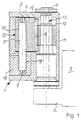
- Torsion bar door locks equipped motor vehicle door hinges exist from a first, which can be attached to a door arrangement part, by a correspondingly machined length section of a hinge profile formed hinge half 1 and a second, likewise from one Longitudinal section of a hinge profile formed, one essentially flat stop surface 3 having hinge half 2 and one two hinge halves 1 and 2 pivotally together connecting hinge pin 4.
- the locking device of the torsion bar door lock consists of a straight line in both embodiments Torsion spring rod 5, a locking member 6 and one on the hinge pin 4th arranged detent training 7.
- the torsion spring bar is 5 both ends with a diameter extension and in their area with a circumferential profile in the form of a circumferential knurl 8 or 9 Mistake.
- the torsion spring bar 5 in both illustrated embodiments non-rotatably connected to the locking member 6. He is above it remaining height without contact in a bore recess 10 in Locking member 6 added.
- the torsion spring bar 5 and locking member 6 existing locking device in one Hinge half 1 is arranged, in which the hinge pin 4 with Running seat is mounted, which is arranged on the hinge pin 4
- Detent formation 7 is formed on a detent bushing 11 and by groove-shaped depressions formed with a semicircular profile cross section Has notches 12.
- the detent bushing 11 is by means of it and on the Shaft part 13 of the hinge pin 4 arranged alternately Protrusions 14 and depressions are secured against rotation with hinge pin 4 connected.
- the one with the catches 12 is the Locking bush 11 cooperating end part of the locking member in both each of the illustrated embodiments by means of a locking element 6 rotatably mounted needle 15 is formed.
- the housing of the locking member 6 and the torsion spring bar 5 is in each case one chamber 16 recessed in one hinge half 1 assigned to the hinge pin side in the hinge eye bore 17th opens into one hinge half 1.
- 1 and 2 The embodiment shown is a closing piece 18 in the chamber 16 used, which is stepped and in its lower Area has a bore 19 in which the torsion spring rod 5th partially included and at the bottom over its circumferential knurl 9 is secured against rotation.
- Striker 18 has a semi-cylindrical bearing surface, which a Support bearing 20 for the locking member 6, which in the in Fig. 1 and 2nd embodiment shown has a pear-shaped profile cross-sectional shape and via its partially cylindrical belly part 21 on the support bearing 20th is supported.
- the striker 18 is only one hinted bolt 22 attached in the chamber 16.
- the Locking member 6 is here by means of a plain bearing disc 28 on the step of the Striker 18 supported.
- the chamber 16 is for upper commercial area 23 of one hinge half 1 open and when the locking unit is mounted, closed by an end plate 24.
- the torsion spring rod 5 is in here over its lower longitudinal section a blind hole 25 extending beyond the chamber 16 recorded without contact and by means of at its lower end trained circumferential knurl 9 in the bottom of the bore Blind hole 25 set.
- the locking member is in this embodiment designed bow-shaped and at its outer end with at least one partially cylindrical thickening 26 provided, which from one of the upper Length range of the torsion spring rod 5 without contact Bore 10 is penetrated and with its cylindrical outer surface at one Formation of a support bearing 27 complementary partially cylindrical Wall area of the chamber 16 abuts.
- With regard to their cross-sectional shape is the chamber 16 of the bracket shape of the locking member 6 designed accordingly.
- the locking member 6 is here by means of a plain bearing disc 28 on the Recess base of the chamber 16 supported.
- Fig. 5 is a hinge pin 4 having an outer socket 11 5a and 5b show two different sections through the hinge pin 4 shown in perspective in FIG. 5c, wherein the representations in Fig. 5a and Fig. 5b additionally distinguish that in Fig. 5a an axially divided into three sections and bushing 5b shows an axially divided bushing 11.
- the assembled hinge pin 4 shown in FIG. 5 enables it in advantageously, the different parts of hinge pin and Bush 11 in its material quality and / or its processing state and their material properties the respective requirement profile to design accordingly.
- the outer contour can also be trained accordingly.
- In the cross-sectional part of Fig. 5a and in 5b are, for example, on the outer circumference of the bushing 11 trained locking marks 12 shown. If the stop marks just over a part of the axial extension of the socket are required, the Socket division take place in such a way that the one having the locking marks Socket section from the remaining socket sections without locking marks is delimited.
- the non-rotating Connection of the hinge pin core and the external socket can by corresponding complementary to the outer circumference of the Hinge pin core complementary, and on the inner circumference of the socket trained profiles. These profiles can be in Circumferential direction be uniform, such as in the form of Six-shaped structures, as shown in Fig. 5a, or in the form of three or Four-shape profiles can be formed.
- the profiles designed like this be that they are not uniform in the circumferential direction, that is for example on a hexagon or on a four or If a triangle is left out of a corner, it offers this Profile design also has the advantage that an assembly aid for angular assembly of the parts is given. Except for the positive connection is also possible non-positive connection of the hinge pin core and socket, for example by shrinking, or a material fit Connection such as welding, soldering or gluing.
Landscapes
- Engineering & Computer Science (AREA)
- Mechanical Engineering (AREA)
- Hinge Accessories (AREA)
- Lock And Its Accessories (AREA)
- Closing And Opening Devices For Wings, And Checks For Wings (AREA)
- Body Structure For Vehicles (AREA)
- Refrigerator Housings (AREA)
- Hinges (AREA)
- Connection Of Plates (AREA)
- Motor Or Generator Cooling System (AREA)
Applications Claiming Priority (3)
| Application Number | Priority Date | Filing Date | Title |
|---|---|---|---|
| DE19855470 | 1998-12-01 | ||
| DE19855470A DE19855470C2 (de) | 1998-12-01 | 1998-12-01 | In ein Kraftwagentürscharnier integrierter Türfeststeller |
| PCT/DE1999/003870 WO2000032896A1 (de) | 1998-12-01 | 1999-11-30 | In ein kraftwagentürscharnier integrierter türfeststeller |
Publications (2)
| Publication Number | Publication Date |
|---|---|
| EP1135570A1 EP1135570A1 (de) | 2001-09-26 |
| EP1135570B1 true EP1135570B1 (de) | 2002-07-03 |
Family
ID=7889666
Family Applications (1)
| Application Number | Title | Priority Date | Filing Date |
|---|---|---|---|
| EP99963280A Expired - Lifetime EP1135570B1 (de) | 1998-12-01 | 1999-11-30 | In ein kraftwagentürscharnier integrierter türfeststeller |
Country Status (10)
| Country | Link |
|---|---|
| EP (1) | EP1135570B1 (cs) |
| JP (1) | JP2002531732A (cs) |
| CN (1) | CN1328615A (cs) |
| AT (1) | ATE220170T1 (cs) |
| AU (1) | AU1964600A (cs) |
| BR (1) | BR9915845A (cs) |
| CZ (1) | CZ20011925A3 (cs) |
| DE (3) | DE19855470C2 (cs) |
| MX (1) | MXPA01005498A (cs) |
| WO (1) | WO2000032896A1 (cs) |
Families Citing this family (2)
| Publication number | Priority date | Publication date | Assignee | Title |
|---|---|---|---|---|
| DE10009049A1 (de) * | 2000-02-25 | 2002-01-03 | Ulrich Schnepel | System zum "leichten" Einrasten bei Tür,- Fenster,- und Möbelbändern |
| US7203996B2 (en) * | 2000-09-13 | 2007-04-17 | Friedr. Fingscheidt Gmbh | Hinge door arrester for vehicle doors |
Family Cites Families (3)
| Publication number | Priority date | Publication date | Assignee | Title |
|---|---|---|---|---|
| US3820192A (en) * | 1973-08-21 | 1974-06-28 | Aisin Seiki | Door hinge unit |
| DE4240362A1 (de) * | 1992-12-01 | 1994-06-09 | Scharwaechter Gmbh Co Kg | An ein Türscharnier angeschlossener Drehstab-Türfeststeller |
| DE29713995U1 (de) * | 1997-08-08 | 1997-09-25 | Lunke & Sohn AG, 58455 Witten | Türscharnier mit Feststeller |
-
1998
- 1998-12-01 DE DE19855470A patent/DE19855470C2/de not_active Expired - Fee Related
-
1999
- 1999-11-30 CZ CZ20011925A patent/CZ20011925A3/cs unknown
- 1999-11-30 AU AU19646/00A patent/AU1964600A/en not_active Abandoned
- 1999-11-30 DE DE19982563T patent/DE19982563D2/de not_active Expired - Fee Related
- 1999-11-30 JP JP2000585517A patent/JP2002531732A/ja not_active Withdrawn
- 1999-11-30 DE DE59901975T patent/DE59901975D1/de not_active Expired - Lifetime
- 1999-11-30 AT AT99963280T patent/ATE220170T1/de not_active IP Right Cessation
- 1999-11-30 BR BR9915845-0A patent/BR9915845A/pt not_active Application Discontinuation
- 1999-11-30 MX MXPA01005498A patent/MXPA01005498A/es unknown
- 1999-11-30 WO PCT/DE1999/003870 patent/WO2000032896A1/de not_active Ceased
- 1999-11-30 CN CN99813883A patent/CN1328615A/zh active Pending
- 1999-11-30 EP EP99963280A patent/EP1135570B1/de not_active Expired - Lifetime
Also Published As
| Publication number | Publication date |
|---|---|
| CN1328615A (zh) | 2001-12-26 |
| DE19855470A1 (de) | 2000-06-08 |
| JP2002531732A (ja) | 2002-09-24 |
| BR9915845A (pt) | 2001-12-11 |
| DE19855470C2 (de) | 2000-12-28 |
| AU1964600A (en) | 2000-06-19 |
| ATE220170T1 (de) | 2002-07-15 |
| DE59901975D1 (de) | 2002-08-08 |
| EP1135570A1 (de) | 2001-09-26 |
| DE19982563D2 (de) | 2001-11-08 |
| WO2000032896A1 (de) | 2000-06-08 |
| MXPA01005498A (es) | 2002-07-02 |
| CZ20011925A3 (cs) | 2002-04-17 |
Similar Documents
| Publication | Publication Date | Title |
|---|---|---|
| EP0816610B1 (de) | Kraftwagentürscharnier | |
| EP1388630B1 (de) | Scharnier | |
| EP3837411B1 (de) | Türfeststeller | |
| DE19619473A1 (de) | Mit einem aushängbaren Türscharnier baulich vereinigter Türfeststeller | |
| EP0794308A1 (de) | Drehstab-Türfeststeller für Kraftwagentüren | |
| EP1068419B1 (de) | Mit einem türscharnier baulich vereinigter türfeststeller | |
| EP1135570B1 (de) | In ein kraftwagentürscharnier integrierter türfeststeller | |
| DE19600063A1 (de) | Kraftwagentürscharnier mit Brems- und Haltefunktion | |
| EP1073820A1 (de) | Kraftwagentürscharnier mit integrierter brems- und haltefunktion | |
| EP0893564B1 (de) | Drehlager für Fenster oder Türen | |
| DE29821472U1 (de) | In ein Kraftwagentürscharnier integrierter Türfeststeller | |
| DE29611580U1 (de) | Kraftwagentürfeststeller | |
| EP0600226B1 (de) | An ein Türscharnier angeschlossener Drehstab-Türfeststeller | |
| EP0943770B1 (de) | Tür- oder Fensterband | |
| DE29617518U1 (de) | Türfeststeller | |
| DE2342641C3 (de) | Türangelanordnung | |
| EP0612903B1 (de) | Torsionsband-Türfeststeller für Kraftwagentüren | |
| DE29604089U1 (de) | Drehstab-Türfeststeller für Kraftwagentüren | |
| EP1068418B1 (de) | Drehstab-türfeststeller für kraftwagentüren | |
| DE20207354U1 (de) | Band für Fenster, Türen o.dgl. | |
| DE102004015475A1 (de) | Gelenkband | |
| DE9216326U1 (de) | An ein Türscharnier angeschlossener Drehstab-Türfeststeller | |
| DE8709748U1 (de) | Türfeststeller, insbesondere für Kraftwagentüren | |
| DE19856487A1 (de) | Scharnier | |
| DE4006572C1 (en) | Motor vehicle door stop - has clamping sleeve acting on bearing bolt longitudinally of arm |
Legal Events
| Date | Code | Title | Description |
|---|---|---|---|
| PUAI | Public reference made under article 153(3) epc to a published international application that has entered the european phase |
Free format text: ORIGINAL CODE: 0009012 |
|
| 17P | Request for examination filed |
Effective date: 20010518 |
|
| AK | Designated contracting states |
Kind code of ref document: A1 Designated state(s): AT BE CH CY DE DK ES FI FR GB GR IE IT LI LU MC NL PT SE |
|
| AX | Request for extension of the european patent |
Free format text: AL;LT;LV;MK;RO;SI |
|
| 17Q | First examination report despatched |
Effective date: 20010924 |
|
| GRAG | Despatch of communication of intention to grant |
Free format text: ORIGINAL CODE: EPIDOS AGRA |
|
| GRAG | Despatch of communication of intention to grant |
Free format text: ORIGINAL CODE: EPIDOS AGRA |
|
| GRAH | Despatch of communication of intention to grant a patent |
Free format text: ORIGINAL CODE: EPIDOS IGRA |
|
| GRAH | Despatch of communication of intention to grant a patent |
Free format text: ORIGINAL CODE: EPIDOS IGRA |
|
| GRAA | (expected) grant |
Free format text: ORIGINAL CODE: 0009210 |
|
| AK | Designated contracting states |
Kind code of ref document: B1 Designated state(s): AT BE CH CY DE DK ES FI FR GB GR IE IT LI LU MC NL PT SE |
|
| PG25 | Lapsed in a contracting state [announced via postgrant information from national office to epo] |
Ref country code: NL Free format text: LAPSE BECAUSE OF FAILURE TO SUBMIT A TRANSLATION OF THE DESCRIPTION OR TO PAY THE FEE WITHIN THE PRESCRIBED TIME-LIMIT Effective date: 20020703 Ref country code: IT Free format text: LAPSE BECAUSE OF FAILURE TO SUBMIT A TRANSLATION OF THE DESCRIPTION OR TO PAY THE FEE WITHIN THE PRESCRIBED TIME-LIMIT;WARNING: LAPSES OF ITALIAN PATENTS WITH EFFECTIVE DATE BEFORE 2007 MAY HAVE OCCURRED AT ANY TIME BEFORE 2007. THE CORRECT EFFECTIVE DATE MAY BE DIFFERENT FROM THE ONE RECORDED. Effective date: 20020703 Ref country code: IE Free format text: LAPSE BECAUSE OF FAILURE TO SUBMIT A TRANSLATION OF THE DESCRIPTION OR TO PAY THE FEE WITHIN THE PRESCRIBED TIME-LIMIT Effective date: 20020703 Ref country code: GR Free format text: LAPSE BECAUSE OF FAILURE TO SUBMIT A TRANSLATION OF THE DESCRIPTION OR TO PAY THE FEE WITHIN THE PRESCRIBED TIME-LIMIT Effective date: 20020703 Ref country code: GB Free format text: LAPSE BECAUSE OF FAILURE TO SUBMIT A TRANSLATION OF THE DESCRIPTION OR TO PAY THE FEE WITHIN THE PRESCRIBED TIME-LIMIT Effective date: 20020703 Ref country code: FR Free format text: LAPSE BECAUSE OF FAILURE TO SUBMIT A TRANSLATION OF THE DESCRIPTION OR TO PAY THE FEE WITHIN THE PRESCRIBED TIME-LIMIT Effective date: 20020703 Ref country code: FI Free format text: LAPSE BECAUSE OF FAILURE TO SUBMIT A TRANSLATION OF THE DESCRIPTION OR TO PAY THE FEE WITHIN THE PRESCRIBED TIME-LIMIT Effective date: 20020703 |
|
| REF | Corresponds to: |
Ref document number: 220170 Country of ref document: AT Date of ref document: 20020715 Kind code of ref document: T |
|
| REG | Reference to a national code |
Ref country code: CH Ref legal event code: EP |
|
| REG | Reference to a national code |
Ref country code: IE Ref legal event code: FG4D Free format text: GERMAN |
|
| REF | Corresponds to: |
Ref document number: 59901975 Country of ref document: DE Date of ref document: 20020808 |
|
| PG25 | Lapsed in a contracting state [announced via postgrant information from national office to epo] |
Ref country code: SE Free format text: LAPSE BECAUSE OF FAILURE TO SUBMIT A TRANSLATION OF THE DESCRIPTION OR TO PAY THE FEE WITHIN THE PRESCRIBED TIME-LIMIT Effective date: 20021003 Ref country code: PT Free format text: LAPSE BECAUSE OF FAILURE TO SUBMIT A TRANSLATION OF THE DESCRIPTION OR TO PAY THE FEE WITHIN THE PRESCRIBED TIME-LIMIT Effective date: 20021003 Ref country code: DK Free format text: LAPSE BECAUSE OF FAILURE TO SUBMIT A TRANSLATION OF THE DESCRIPTION OR TO PAY THE FEE WITHIN THE PRESCRIBED TIME-LIMIT Effective date: 20021003 |
|
| PG25 | Lapsed in a contracting state [announced via postgrant information from national office to epo] |
Ref country code: LU Free format text: LAPSE BECAUSE OF NON-PAYMENT OF DUE FEES Effective date: 20021130 Ref country code: CY Free format text: LAPSE BECAUSE OF FAILURE TO SUBMIT A TRANSLATION OF THE DESCRIPTION OR TO PAY THE FEE WITHIN THE PRESCRIBED TIME-LIMIT Effective date: 20021130 Ref country code: BE Free format text: LAPSE BECAUSE OF NON-PAYMENT OF DUE FEES Effective date: 20021130 Ref country code: AT Free format text: LAPSE BECAUSE OF NON-PAYMENT OF DUE FEES Effective date: 20021130 |
|
| NLV1 | Nl: lapsed or annulled due to failure to fulfill the requirements of art. 29p and 29m of the patents act | ||
| GBV | Gb: ep patent (uk) treated as always having been void in accordance with gb section 77(7)/1977 [no translation filed] |
Effective date: 20020703 |
|
| PG25 | Lapsed in a contracting state [announced via postgrant information from national office to epo] |
Ref country code: ES Free format text: LAPSE BECAUSE OF FAILURE TO SUBMIT A TRANSLATION OF THE DESCRIPTION OR TO PAY THE FEE WITHIN THE PRESCRIBED TIME-LIMIT Effective date: 20030130 |
|
| EN | Fr: translation not filed | ||
| REG | Reference to a national code |
Ref country code: IE Ref legal event code: FD4D Ref document number: 1135570E Country of ref document: IE |
|
| PLBE | No opposition filed within time limit |
Free format text: ORIGINAL CODE: 0009261 |
|
| STAA | Information on the status of an ep patent application or granted ep patent |
Free format text: STATUS: NO OPPOSITION FILED WITHIN TIME LIMIT |
|
| BERE | Be: lapsed |
Owner name: ED. *SCHARWACHTER G.M.B.H. Effective date: 20021130 |
|
| PG25 | Lapsed in a contracting state [announced via postgrant information from national office to epo] |
Ref country code: MC Free format text: LAPSE BECAUSE OF NON-PAYMENT OF DUE FEES Effective date: 20030601 |
|
| 26N | No opposition filed |
Effective date: 20030404 |
|
| PG25 | Lapsed in a contracting state [announced via postgrant information from national office to epo] |
Ref country code: LI Free format text: LAPSE BECAUSE OF NON-PAYMENT OF DUE FEES Effective date: 20031130 Ref country code: CH Free format text: LAPSE BECAUSE OF NON-PAYMENT OF DUE FEES Effective date: 20031130 |
|
| REG | Reference to a national code |
Ref country code: CH Ref legal event code: PL |
|
| REG | Reference to a national code |
Ref country code: DE Ref legal event code: R082 Ref document number: 59901975 Country of ref document: DE Representative=s name: BONNEKAMP & SPARING, DE Effective date: 20110812 Ref country code: DE Ref legal event code: R081 Ref document number: 59901975 Country of ref document: DE Owner name: EDSCHA ENGINEERING GMBH, DE Free format text: FORMER OWNER: ED. SCHARWAECHTER GMBH, 42855 REMSCHEID, DE Effective date: 20110812 |
|
| PGFP | Annual fee paid to national office [announced via postgrant information from national office to epo] |
Ref country code: DE Payment date: 20181120 Year of fee payment: 20 |
|
| REG | Reference to a national code |
Ref country code: DE Ref legal event code: R071 Ref document number: 59901975 Country of ref document: DE |