EP1136697A2 - Appareil de commande de bougie à incandescence , bougie, et méthode pour détecter des ions dans la chambre de combustion d'un moteur - Google Patents
Appareil de commande de bougie à incandescence , bougie, et méthode pour détecter des ions dans la chambre de combustion d'un moteur Download PDFInfo
- Publication number
- EP1136697A2 EP1136697A2 EP01302648A EP01302648A EP1136697A2 EP 1136697 A2 EP1136697 A2 EP 1136697A2 EP 01302648 A EP01302648 A EP 01302648A EP 01302648 A EP01302648 A EP 01302648A EP 1136697 A2 EP1136697 A2 EP 1136697A2
- Authority
- EP
- European Patent Office
- Prior art keywords
- glow plug
- heating element
- resistivity
- engine
- energization
- Prior art date
- Legal status (The legal status is an assumption and is not a legal conclusion. Google has not performed a legal analysis and makes no representation as to the accuracy of the status listed.)
- Granted
Links
- 238000002485 combustion reaction Methods 0.000 title claims abstract description 55
- 150000002500 ions Chemical class 0.000 title claims description 66
- 238000000034 method Methods 0.000 title claims description 27
- 239000000919 ceramic Substances 0.000 claims abstract description 146
- 239000000758 substrate Substances 0.000 claims abstract description 75
- 238000010438 heat treatment Methods 0.000 claims description 126
- 239000000446 fuel Substances 0.000 claims description 66
- 238000002347 injection Methods 0.000 claims description 42
- 239000007924 injection Substances 0.000 claims description 42
- 238000001514 detection method Methods 0.000 abstract description 25
- 230000004044 response Effects 0.000 abstract description 4
- 238000010792 warming Methods 0.000 description 19
- 239000000203 mixture Substances 0.000 description 16
- 230000008569 process Effects 0.000 description 16
- 238000005259 measurement Methods 0.000 description 13
- 238000009472 formulation Methods 0.000 description 10
- XLYOFNOQVPJJNP-UHFFFAOYSA-N water Substances O XLYOFNOQVPJJNP-UHFFFAOYSA-N 0.000 description 9
- 229910052581 Si3N4 Inorganic materials 0.000 description 6
- HQVNEWCFYHHQES-UHFFFAOYSA-N silicon nitride Chemical compound N12[Si]34N5[Si]62N3[Si]51N64 HQVNEWCFYHHQES-UHFFFAOYSA-N 0.000 description 6
- 238000009413 insulation Methods 0.000 description 5
- ATJFFYVFTNAWJD-UHFFFAOYSA-N Tin Chemical compound [Sn] ATJFFYVFTNAWJD-UHFFFAOYSA-N 0.000 description 4
- 230000007797 corrosion Effects 0.000 description 4
- 238000005260 corrosion Methods 0.000 description 4
- 238000012545 processing Methods 0.000 description 4
- 102220588433 Keratin, type I cytoskeletal 18_S42A_mutation Human genes 0.000 description 3
- 229910020968 MoSi2 Inorganic materials 0.000 description 3
- 230000000694 effects Effects 0.000 description 3
- 230000005012 migration Effects 0.000 description 3
- 238000013508 migration Methods 0.000 description 3
- 239000000523 sample Substances 0.000 description 3
- 238000005245 sintering Methods 0.000 description 3
- WFKWXMTUELFFGS-UHFFFAOYSA-N tungsten Chemical compound [W] WFKWXMTUELFFGS-UHFFFAOYSA-N 0.000 description 3
- 229910052721 tungsten Inorganic materials 0.000 description 3
- XEEYBQQBJWHFJM-UHFFFAOYSA-N Iron Chemical compound [Fe] XEEYBQQBJWHFJM-UHFFFAOYSA-N 0.000 description 2
- 102220585558 T cell receptor gamma constant 1_S41A_mutation Human genes 0.000 description 2
- 102220536518 THAP domain-containing protein 1_S51A_mutation Human genes 0.000 description 2
- 238000010586 diagram Methods 0.000 description 2
- QDOXWKRWXJOMAK-UHFFFAOYSA-N dichromium trioxide Chemical compound O=[Cr]O[Cr]=O QDOXWKRWXJOMAK-UHFFFAOYSA-N 0.000 description 2
- 230000002349 favourable effect Effects 0.000 description 2
- PCHJSUWPFVWCPO-UHFFFAOYSA-N gold Chemical compound [Au] PCHJSUWPFVWCPO-UHFFFAOYSA-N 0.000 description 2
- 229910052737 gold Inorganic materials 0.000 description 2
- 239000010931 gold Substances 0.000 description 2
- 230000020169 heat generation Effects 0.000 description 2
- 239000012212 insulator Substances 0.000 description 2
- 229910052751 metal Inorganic materials 0.000 description 2
- 239000002184 metal Substances 0.000 description 2
- 230000003647 oxidation Effects 0.000 description 2
- 238000007254 oxidation reaction Methods 0.000 description 2
- 230000005855 radiation Effects 0.000 description 2
- 230000009467 reduction Effects 0.000 description 2
- 230000000087 stabilizing effect Effects 0.000 description 2
- 239000010937 tungsten Substances 0.000 description 2
- UONOETXJSWQNOL-UHFFFAOYSA-N tungsten carbide Chemical compound [W+]#[C-] UONOETXJSWQNOL-UHFFFAOYSA-N 0.000 description 2
- 229910021359 Chromium(II) silicide Inorganic materials 0.000 description 1
- 235000001537 Ribes X gardonianum Nutrition 0.000 description 1
- 235000001535 Ribes X utile Nutrition 0.000 description 1
- 235000016919 Ribes petraeum Nutrition 0.000 description 1
- 244000281247 Ribes rubrum Species 0.000 description 1
- 235000002355 Ribes spicatum Nutrition 0.000 description 1
- 102220536512 THAP domain-containing protein 1_S52A_mutation Human genes 0.000 description 1
- 229910004166 TaN Inorganic materials 0.000 description 1
- 229910008479 TiSi2 Inorganic materials 0.000 description 1
- 229910021541 Vanadium(III) oxide Inorganic materials 0.000 description 1
- 229910008814 WSi2 Inorganic materials 0.000 description 1
- 229910008322 ZrN Inorganic materials 0.000 description 1
- 230000005856 abnormality Effects 0.000 description 1
- PNEYBMLMFCGWSK-UHFFFAOYSA-N aluminium oxide Inorganic materials [O-2].[O-2].[O-2].[Al+3].[Al+3] PNEYBMLMFCGWSK-UHFFFAOYSA-N 0.000 description 1
- DFJQEGUNXWZVAH-UHFFFAOYSA-N bis($l^{2}-silanylidene)titanium Chemical compound [Si]=[Ti]=[Si] DFJQEGUNXWZVAH-UHFFFAOYSA-N 0.000 description 1
- 239000004568 cement Substances 0.000 description 1
- 229910010293 ceramic material Inorganic materials 0.000 description 1
- 230000008859 change Effects 0.000 description 1
- 238000006243 chemical reaction Methods 0.000 description 1
- 229910052804 chromium Inorganic materials 0.000 description 1
- 238000007796 conventional method Methods 0.000 description 1
- 239000000498 cooling water Substances 0.000 description 1
- 229910052593 corundum Inorganic materials 0.000 description 1
- 238000005336 cracking Methods 0.000 description 1
- 230000007547 defect Effects 0.000 description 1
- 230000003111 delayed effect Effects 0.000 description 1
- 230000006866 deterioration Effects 0.000 description 1
- 230000002542 deteriorative effect Effects 0.000 description 1
- 230000002708 enhancing effect Effects 0.000 description 1
- 230000007613 environmental effect Effects 0.000 description 1
- VQCBHWLJZDBHOS-UHFFFAOYSA-N erbium(III) oxide Inorganic materials O=[Er]O[Er]=O VQCBHWLJZDBHOS-UHFFFAOYSA-N 0.000 description 1
- 238000000227 grinding Methods 0.000 description 1
- 229910052735 hafnium Inorganic materials 0.000 description 1
- 230000006872 improvement Effects 0.000 description 1
- 238000001746 injection moulding Methods 0.000 description 1
- 229910052742 iron Inorganic materials 0.000 description 1
- 239000000463 material Substances 0.000 description 1
- 238000012986 modification Methods 0.000 description 1
- 230000004048 modification Effects 0.000 description 1
- 229910003465 moissanite Inorganic materials 0.000 description 1
- 238000000465 moulding Methods 0.000 description 1
- 229910052758 niobium Inorganic materials 0.000 description 1
- 150000004767 nitrides Chemical class 0.000 description 1
- 239000000843 powder Substances 0.000 description 1
- 230000002265 prevention Effects 0.000 description 1
- 238000000746 purification Methods 0.000 description 1
- 229910021332 silicide Inorganic materials 0.000 description 1
- FVBUAEGBCNSCDD-UHFFFAOYSA-N silicide(4-) Chemical compound [Si-4] FVBUAEGBCNSCDD-UHFFFAOYSA-N 0.000 description 1
- 229910010271 silicon carbide Inorganic materials 0.000 description 1
- 229910052709 silver Inorganic materials 0.000 description 1
- 239000004332 silver Substances 0.000 description 1
- 239000000725 suspension Substances 0.000 description 1
- 229910052715 tantalum Inorganic materials 0.000 description 1
- 238000012360 testing method Methods 0.000 description 1
- 239000010936 titanium Substances 0.000 description 1
- 229910052719 titanium Inorganic materials 0.000 description 1
- MTPVUVINMAGMJL-UHFFFAOYSA-N trimethyl(1,1,2,2,2-pentafluoroethyl)silane Chemical compound C[Si](C)(C)C(F)(F)C(F)(F)F MTPVUVINMAGMJL-UHFFFAOYSA-N 0.000 description 1
- ZNOKGRXACCSDPY-UHFFFAOYSA-N tungsten(VI) oxide Inorganic materials O=[W](=O)=O ZNOKGRXACCSDPY-UHFFFAOYSA-N 0.000 description 1
- 229910052720 vanadium Inorganic materials 0.000 description 1
- 229910001845 yogo sapphire Inorganic materials 0.000 description 1
- FIXNOXLJNSSSLJ-UHFFFAOYSA-N ytterbium(III) oxide Inorganic materials O=[Yb]O[Yb]=O FIXNOXLJNSSSLJ-UHFFFAOYSA-N 0.000 description 1
- RUDFQVOCFDJEEF-UHFFFAOYSA-N yttrium(III) oxide Inorganic materials [O-2].[O-2].[O-2].[Y+3].[Y+3] RUDFQVOCFDJEEF-UHFFFAOYSA-N 0.000 description 1
- 229910052726 zirconium Inorganic materials 0.000 description 1
Images




Classifications
-
- F—MECHANICAL ENGINEERING; LIGHTING; HEATING; WEAPONS; BLASTING
- F02—COMBUSTION ENGINES; HOT-GAS OR COMBUSTION-PRODUCT ENGINE PLANTS
- F02P—IGNITION, OTHER THAN COMPRESSION IGNITION, FOR INTERNAL-COMBUSTION ENGINES; TESTING OF IGNITION TIMING IN COMPRESSION-IGNITION ENGINES
- F02P19/00—Incandescent ignition, e.g. during starting of internal combustion engines; Combination of incandescent and spark ignition
- F02P19/02—Incandescent ignition, e.g. during starting of internal combustion engines; Combination of incandescent and spark ignition electric, e.g. layout of circuits of apparatus having glowing plugs
- F02P19/028—Incandescent ignition, e.g. during starting of internal combustion engines; Combination of incandescent and spark ignition electric, e.g. layout of circuits of apparatus having glowing plugs the glow plug being combined with or used as a sensor
-
- F—MECHANICAL ENGINEERING; LIGHTING; HEATING; WEAPONS; BLASTING
- F02—COMBUSTION ENGINES; HOT-GAS OR COMBUSTION-PRODUCT ENGINE PLANTS
- F02P—IGNITION, OTHER THAN COMPRESSION IGNITION, FOR INTERNAL-COMBUSTION ENGINES; TESTING OF IGNITION TIMING IN COMPRESSION-IGNITION ENGINES
- F02P17/00—Testing of ignition installations, e.g. in combination with adjusting; Testing of ignition timing in compression-ignition engines
- F02P17/12—Testing characteristics of the spark, ignition voltage or current
-
- F—MECHANICAL ENGINEERING; LIGHTING; HEATING; WEAPONS; BLASTING
- F02—COMBUSTION ENGINES; HOT-GAS OR COMBUSTION-PRODUCT ENGINE PLANTS
- F02P—IGNITION, OTHER THAN COMPRESSION IGNITION, FOR INTERNAL-COMBUSTION ENGINES; TESTING OF IGNITION TIMING IN COMPRESSION-IGNITION ENGINES
- F02P19/00—Incandescent ignition, e.g. during starting of internal combustion engines; Combination of incandescent and spark ignition
- F02P19/02—Incandescent ignition, e.g. during starting of internal combustion engines; Combination of incandescent and spark ignition electric, e.g. layout of circuits of apparatus having glowing plugs
- F02P19/025—Incandescent ignition, e.g. during starting of internal combustion engines; Combination of incandescent and spark ignition electric, e.g. layout of circuits of apparatus having glowing plugs with means for determining glow plug temperature or glow plug resistance
Definitions
- the present invention relates to a glow plug control apparatus for controlling a glow plug so as to accelerate the ignition/combustion of a fuel by said glow plug or detect ions generated during the combustion of a fuel by said glow plug and a glow plug therefor.
- a feedback control has been proposed involving the use of results of detection of ions produced during the combustion of a fuel for the purpose of controlling the timing or amount of fuel injection in the engine.
- a method of detecting ions there is particularly proposed a method involving the measurement of ionic current flowing due to the presence of ions produced by the application of a voltage across the glow plug and the inner wall of the combustion chamber of an engine.
- a glow plug has played a role ranging from aiding actuation to stabilizing the engine drive until the completion of warming up and thus has normally not been energized after the completion of warming up.
- it has been made obvious that it is effective for the reduction of vibration or noise of the engine and purification of exhaust gas to energize the glow plug even after the warming-up of the engine so that the glow plug is kept at a relatively high temperature.
- a system has been proposed involving the energization of a glow plug depending on the operating conditions for the purpose of controlling the temperature of the glow plug to not lower than a predetermined temperature.
- JP-A-10-9113 and JP-A-10-77945 merely disclose a system involving the energization of a glow plug before actuation (pre-glow period) and during the warming-up of the engine (after-glow period) and the use of the glow plug only for the detection of ionic current.
- the invention disclosed in the above cited patents cannot energize the glow plug even after the completion of warming-up to detect ionic current and control the engine. It is preferred that ionic current be detected to control the engine also in the stage before the completion of warming-up such as pre-glow period and after-glow period.
- a glow plug control apparatus comprising a glow plug including a housing fixed to an engine, a heating element insulated from the housing which generates heat when energized by electric current supplied through two conductive paths at least either before or after the completion of warming-up of the engine and a ceramic heater having an exposed portion which is heated by the heating element and exposed to the interior of the combustion chamber of the engine; a glow plug energization controlling means for controlling the energization of the heating element of the glow plug depending on the surface temperature of the exposed portion so as to raise or keep the surface temperature to not lower than a predetermined temperature; an ion detecting means for detecting ions in the combustion chamber using the glow plug; a switching means for switching the state of the glow plug from the state of being controlled in energization by the glow plug controlling means to the state of being detected in ion by the ion detecting means or vice versa; and a switching command means for commanding the switching from the state of being controlled in energization
- the glow plug energization controlling means controls such that the surface temperature of the exposed portion of the ceramic heater is raised or kept to not lower than a predetermined temperature.
- the switching command means commands the switching means to switch the state of being controlled in energization to the state of being detected in ions for a predetermined period of time from the time of injection of fuel.
- the glow plug is energized before the actuation of the engine.
- the detection of ions is not conducted before the temperature thereof rises from a temperature as low as ordinary temperature to the predetermined temperature.
- the state of the glow plug is switched from the state of being controlled in energization to the state of being detected in ions for a predetermined period of time from the time of injection of a fuel into the combustion chamber. Accordingly, the detection of ions can be conducted in the internals of the rise of the temperature of the glow plug. Thus, engine control during actuation is made possible.
- the surface temperature of the exposed portion of the glow plug is kept to the predetermined temperature at lowest, making it possible to detect ions. Accordingly, the engine control during warming-up can be conducted.
- the surface temperature of the exposed portion of the glow plug is kept to the predetermined tempearture at lowest even after the completion of warming-up.- In this manner, the vibration and noise of the engine can be lessened and the exhaust gas can be cleaned. Further, ions produced by the combustion of the fuel can be detected, making it possible to control the engine.
- the foregoing control may be conducted either before or after the completion of warming up of the engine. Accordingly, the foregoing control may be conducted at any time between pre-glow period before the actuation of the engine and after-glow period after the actuation of the engine and during the period after the completion of warming up.
- control may be conducted at any time between before the actuation of the engine and before the completion of warming up.
- the detection of ions is not conducted before the temperature of the glow plug which has been energized reaches a predetermined temperature from a value as low as ordinary temperature. Therefore, the temperature of the glow plug can be raised without hindrance due to switching to the state of being detected in ionic current, giving favorable actuation properties.
- similar control can be conducted even after the completion of warming up as mentioned above.
- control different from that made before the completion of warming up may be conducted after the completion of warming up.
- the foregoing control may be conducted at any time after the completion of warming up.
- the surface temperature of the exposed portion of the glow plug can be not lower than the predetermined temperature. Therefore, the vibration and noise of the engine can be lessened and the exhaust gas can be cleaned. Further, ions produced by the combustion of the fuel can be detected, making it possible to control the engine.
- thermocouple may be embedded in the ceramic insulator.
- the temperature of the exposed portion can be measured by means of such a temperature sensor such as thermocouple.
- the surface temperature of the exposed portion may be estimated from the resistivity of the heating element on the basis of previously determined relationship between the resistivity of the heating element and the surface temperature of the exposed portion.
- the predetermined period of time from the time of injection of fuel commanded by the switching command means can be a predetermined value represented, e.g., by the crank angle from the time of injection of fuel. Further, the foregoing period of time from the time of injection of fuel is preferably selected depending on the load represented by the rotary speed of the engine, the opening of the accelerator, the position of the accelerator or the like. This is because the period of time during which ions can be detected to obtain data useful for engine control varies with the rotary speed of the engine or load.
- the glow plug control apparatus may be arranged such that the foregoing predetermined temperature is selected from the range of from 500°C to 900°C.
- the surface temperature of the exposed portion of the glow plug varies with the rotary speed of the engine or the load conditions and thus falls within a range of from about 200°C to 900°C. In other words, when the engine is rotated at a low speed under a low load, the surface temperature of the exposed portion of the glow plug may be lowered to about 200°C.
- the predetermined temperature of the invention is selected from a range of from 500°C to 900°C.
- the glow plug should be kept at a predetermined temperature selected from a range of 500°C to 900°C.
- the predetermined temperature is selected from a range of from 500°C to 900°C
- the resulting effect of stabilizing the ignition and combustion of the fuel in the engine is insufficient.
- the predetermined temperature exceeds 900°C
- the glow plug is kept at a high temperature. In other words, when control is conducted such that the temperature of the glow plug is kept beyond 900°C, the durability of the glow plug can be easily deteriorated. This is also because as the electric power consumed to energize the glow plug increases, the fuel economy lowers.
- the heating element is covered by a ceramic substrate and the resistivity of the substrate between the heating element and the surface of the ceramic substrate is from 10 k ⁇ to 1 g ⁇ when the surface temperature of the exposed portion is from the predetermined temperature to 1,200°C.
- the heating element of the ceramic heater used in the glow plug control apparatus is covered by a ceramic substrate and thus cannot be subject to corrosion or oxidation due to combustion flame.
- the ceramic heater is allowed to generate heat in a stabilized manner or the detection of ions can be conducted in a stabilized manner.
- the resistivity of the ceramic substrate interposed therebetween must be somewhat low.
- the glow plug to be used in the glow plug control apparatus of the invention is arranged such that the resistivity between the heating element and the ceramic substrate is from 10 k ⁇ to 1 G ⁇ when the surface temperature of the exposed portion of the glow plug ranges from the predetermined temperature to 1,200°C.
- ions can be detected within this temperature range.
- the reason why the surface temperature of the exposed portion of the glow plug should fall within a range of from the predetermined tempearture to 1,200°C is that when the surface temperature of the exposed portion of the glow plug is not lower than the predetermined temperature, the state of the glow plug is switched to the state of being detected in ions for a predetermined period of time. Further, the surface temperature of the exposed portion of the glow plug may reach 1,200°C at highest in the initial stage of actuation of engine.
- the resistivity of the substrate should fall within a range of from 10 k ⁇ to 1 G ⁇ is that when the resistivity of the substrate is as extremely high as greater than 1 G ⁇ , the resulting ionic current is so extremely small that it can difficultly be detected. Accordingly, the resistivity of the substrate is preferably 1 G ⁇ or less. On the contrary, when the resistivity of the ceramic substrate is too low, current flows through the ceramic substrate across the two ends of the heating element to cause defects such as migration. Accordingly, the resistivity of the substrate is preferably 10 k ⁇ or more.
- a glow plug control apparatus comprising a glow plug comprising a housing fixed to an engine, a heating element insulated from the housing which generates heat when energized by electric current supplied through two conductive paths at least either before or after the completion of warming-up of the engine and a ceramic heater having an exposed portion which is heated by the heating element and exposed to the interior of the combustion chamber of the engine; a glow plug energization controlling means for controlling the energization of the heating element of the glow plug depending on the resistivity of the heating element so as to raise or keep the resistivity to not lower than a predetermined resistivity; an ion detecting means for detecting ions in the combustion chamber using the glow plug; a switching means for switching the state of the glow plug from the state of being controlled in energization by the glow plug controlling means to the state of being detected in ions by the ion detecting means or vice versa; and a switching command means for commanding the switching from the state of being controlled in energization to
- the glow plug energization controlling means controls such that the resistivity of the heating element related to the surface temperature of the exposed portion of the ceramic heater is raised or kept to a predetermined resistivity or more.
- the switching command means commands that the switching means be switched from the state of being controlled in energization to the state of being detected in ions for a predetermined period of time from the time of injection of fuel.
- the glow plug is energized to raise the temperature thereof from a temperature as low as ordinary temperature to the predetermined temperature.
- the detection of ions is not conducted before the resistivity of the heating element reaches beyond the predetermined resistivity.
- the state of the switching means is switched from the state of being controlled in energization to the state of being detected in ions for a predetermined period of time from the time of injection of fuel into the combustion chamber. Accordingly, the detection of ions can be conducted in the intervals of raising-up the temperature of the glow plug.
- engine control can be made also during actuation.
- the resistivity of the heating element of the glow plug can be raised to a predetermined resistivity, that is, the surface temperature of the exposed portion can be raised to a predetermined temperature so that the detection of ions can be conducted. Accordingly, engine control can be made also during warming-up.
- the resistivity of the heating element of the glow plug is raised to the predetermined resistivity, that is, the surface temperature of the exposed portion is raised to the predetermined temperature.
- the vibration and noise of the engine can be lessened, and the exhaust gas can be cleaned.
- ions produced by the combustion of the fuel can be detected, making it possible to control the engine.
- the foregoing control may be conducted at least either before or after warming-up of the engine. Accordingly, the foregoing control may be conducted at any time between pre-glow period before the actuation of the engine and after-glow period after the actuation of the engine and during the period after the completion of warming up.
- control may be conducted at any time between before the actuation of the engine and before the completion of warming up.
- the detection of ions is not conducted before the temperature of the glow plug which has been energized reaches a predetermined temperature from a value as low as ordinary temperature. Therefore, the temperature of the glow plug can be raised without hindrance due to switching to the state of being detected in ionic current, giving favorable actuation properties.
- similar control can be conducted even after the completion of warming up as mentioned above.
- control different from that made before the completion of warming up may be conducted after the completion of warming up.
- the foregoing control may be conducted at any time after the completion of warming up.
- the resistivity of the glow plug is not lower than the predetermined resistivity so that the surface temperature of the exposed portion can be raised to not less than the predetermined temperature. Therefore, the vibration and noise of the engine can be lessened and the exhaust gas can be cleaned. Further, ions produced by the combustion of the fuel can be detected, making it possible to control the engine.
- a further means for solving the foregoing problems is a glow plug having a housing, and an heating element insulated from the housing which generates heat when energized by electric current supplied through two conductive paths, characterized in that the heating element has a ceramic heater covered by a ceramic substrate and the resistivity of the substrate between the heating element and the surface of the ceramic substrate is from 10 k ⁇ to 1 G ⁇ when the surface temperature of the forward end of the ceramic heater is from 500°C to 1,200°C.
- the heating element is covered by a ceramic substrate and thus cannot be subject to corrosion or oxidation due to combustion flame.
- the ceramic heater is allowed to generate heat in a stabilized manner.
- the resistivity of the substrate between the heating element and the surface of the ceramic substrate is from 10 k ⁇ to 1 G ⁇ .
- the detection of ions can be conducted.
- the ignition and combustion of fuel can be conducted in a stabilized manner, making it possible to lessen the vibration or noise of the engine and clean the exhaust gas.
- a still further means for solving the problems is a method of detecting ions in the combustion chamber of an engine to which a glow plug is fixed, the glow plug comprising a housing, an heating element insulated from the housing which generates heat when energized by electric current supplied through two conductive paths and a ceramic heater having an exposed portion which is heated by the heating element and exposed to the interior of the combustion chamber.
- the energization of the heating element of the glow plug is controlled depending on the resistivity of the heating element so as to raise or keep the resistivity to not lower than a predetermined resistivity and when the resistivity of the heating element is not lower than the predetermined resistivity, the state of the glow plug is switched from the state of being controlled in energization for a predetermined period of time from the time of injection of fuel into the combustion chamber during which period ions in the combustion chamber are detected.
- energization is controlled in the stage of completion of warming-up of engine such that the resistivity of the heating element is raised or kept to not lower than a predetermined resistivity.
- energization is conducted to generate heat such that the surface temperature of the exposed portion of the ceramic heater reaches a predetermined temperature. Accordingly, even after the warming-up of the engine, the vibration or noise of the engine can be lessened and the exhaust gas can be cleaned.
- It may be arranged such that the detection of ions is conducted even while the warming-up of the engine is not completed yet.
- a glow plug 10 shown in Fig. 1 has a metallic cylindrical housing 1 and a ceramic heater 2.
- the ceramic heater 2 is brazed to an outer metallic cylinder 3 with its forward end (lower end as shown in the drawing) exposed to the exterior.
- the outer cylinder 3 is brazed to the housing 1.
- the ceramic heater 2 has a U-shaped ceramic heating element (heating element) 4, a ceramic substrate 5 covering the ceramic heating element 4, and two leads 6, 7 made of tungsten through which the two ends 4a, 4b of the ceramic heating element 4 are connected to the exterior, respectively.
- the ceramic substrate 5 is made of a ceramic mainly composed of silicon nitride having titanium carbide as an electrically-conductive ceramic incorporated therein in a small amount.
- the ceramic substrate 5 stays to be an insulator at ordinary temperature but lowers in resistivity and shows electrical conductivity as the ambient temperature rises. Silicon nitride shows a gradual drop of insulation resistance with the rise of temperature.
- the ceramic heating element 4 is an electrically-conductive ceramic made of the ceramic material used in the ceramic substrate 5 and tungsten carbite (WC).
- the end 4a of the ceramic heating element 4 is connected to the rear end (upper end as shown in the drawing) of the ceramic heater 2 through the lead 6 and then to a center wire 11 through a coil spring-shaped lead 8.
- the center wire 11 has its forward end (upper end as shown in the drawing) externally threaded to form a terminal portion 11T.
- the other end 4b of the ceramic heating element 4 is connected to the periphery of the central part 2c of the ceramic heater 2 through the lead 7 and then to a terminal sleeve 13 surrounding the longitudinally central portion of the center wire 11.
- the terminal sleeve 13 is insulated from the housing 1 by a cylindrical insulating ring 14 and also from the center wire 11 by a cylindrical insulating sleeve 15 provided along the inner wall of the terminal sleeve 13.
- the glow plug 10 is arranged such that when an electric current is allowed to flow between the center wire 11 (terminal portion 11T) and the terminal sleeve 13, the ceramic heating element 4 generates heat, causing the surface temperature of the forward end 2a of the ceramic heater 2 to rise.
- the ceramic heating element 4 is insulated from the housing 1.
- the ceramic heating element 4 is covered by the ceramic substrate 5.
- the ceramic substrate 5 is made of a material which becomes electrically conductive at elevated temperatures as mentioned above.
- the glow plug 10 can be used as a heat source before the actuation of the engine or in the stage of after-glow. Further, by keeping the glow plug 10 at a high temperature, ions produced between the ceramic insulating element 4 and the engine during the combustion of fuel can be detected through the ceramic substrate 5.
- the relationship between the resistivity Rg of the ceramic heating element 4 of the glow plug 10, the surface temperature Ts of the forward end 2a and the resistivity Ri between the ceramic heating element 4 and the surface of the forward end 2a of the glow plug 10 was examined as follows. Firstly, the forward end 2a of the glow plug 10 is covered by an electrically-conductive metal film. In some detail, gold or silver was vacuum-evaporated onto the forward end 2a of the glow plug 10 to a thickness of about 1 ⁇ m. This is intended to make it possible to measure the substrate resistivity Ri between the ceramic heating element 4 and the forward end 2a of the glow plug 10 in a stabilized manner.
- a constant voltage power supply 23 is connected between the terminal portion 11T and the terminal sleeve 13 of the glow plug 10 via an ammeter 21 and a switch 22.
- a constant voltage Vg of 12 V is supplied from the constant voltage power supply 23 to the glow plug 10 so that the ceramic heating element 4 generates heat to cause the temperature of the forward end 2a of the glow plug 10 to rise.
- the constant voltage power supply there was used a Type PVS20-130 power supply produced by KIKUSUI CO., LTD.
- the temperature of the area on the forward end 2a having the highest surface temperature is measured by an infrared radiation thermometer 24 arranged to cover the region containing the forward end 2a.
- the surface temperature Ts is indicated by a temperature converter 25.
- the infrared radiation thermometer 24 there was used TVS-100 produced by Nippon Avionics Co., Ltd.
- the ceramic heating element 4 rises in its resistivity as the temperature rises. Accordingly, when the relationship between the surface temperature Ts of the forward end 2a and the resistivity Rg of the glow plug 10 is known, the heating element resistivity Rg of the glow plug can be determined from the voltage Vg applied to the glow plug 10 and the current Ig flowing at this time even if the glow plug 10 is mounted on the engine. In this manner, the surface temperature Ts of the forward end 2a can be estimated.
- the forward end 27a of the probe 27 of an insulation resistance meter 26 is brought into contact with the forward end 2a of the glow plug 10 to measure the substrate resistivity Ri between the terminal sleeve 13 and the forward end 27a. In this manner, the substrate resistivity Ri between the ceramic heating element 4 and the surface of the ceramic substrate 5 can be measured.
- the forward end 2a has a metal film such as gold layer formed thereon as mentioned above, making it possible to measure the substrate resistivity Ri in a stabilized manner without being affected by the contact conditions of the probe 27.
- R8340 ULTRA HIGH RESISTANCE METER
- the glow plug 10 according to the present embodiment comprises the ceramic substrate 5 having the formulation B.
- Type % by mass of silicon nitride % by mass of sintering aid % by mass of electrically-conductive ceramic A 90 8 TiN 2 B 85 10 TiC 5 C 80 12 WC 8 D 75 15 MoSi 2 10 E 70 17 SiC 13 Sintering aid: 10Yb 2 O 3 + 1Cr 2 O 3
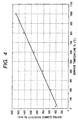
- the relationship between the surface temperature Ts of the exposed portion and the resistivity Rg of the ceramic heating element is shown in Fig. 4.
- the heating element resistivity Rg shows a monotonous linear increase. Accordingly, by knowing the heating element resistivity Rg, the surface temperature Ts can be estimated on the basis of this graph.
- the five glow plugs showed similar relationship between the surface temperature Ts and the heating element resistivity Rg. This is because the five glow plugs comprised similar ceramic heating element 4.
- the glow plug 10 to be used in the present embodiment may be prepared by any conventional method.
- the ceramic heater 2 may be prepared as follows.
- an uncalcined ceramic heating element 4 to which leads 6, 7 made of tungsten wire are attached is formed by injection molding.
- This ceramic heating element 4 is made of a blend of 60% by mass of tungsten carbide (WC) and 40% by weight of a ceramic having the formulation B set forth in Table 1 above.
- a half-solidified uncalcined ceramic substrate 5 has been prepared by press-molding a ceramic powder having the formulation B. Thereafter, the uncalcined ceramic heating element 4 and the leads 6, 7 are disposed in the uncalcined ceramic substrate 5, hot-pressed, and then subjected to grinding or the like to obtain the ceramic heater 2.
- the outline of the glow plug control apparatus 100 according to the present embodiment is shown in Fig. 5.
- the glow plug 10 already described is threaded in a mounting hole 31H formed in the cylinder head 31 of the engine 30 and has the forward end 2a of the ceramic heater 2 exposed in a subsidiary combustion chamber 32 provided in the cylinder head 31.
- the exposed portion 2d acts as a heat source for accelerating the ignition and combustion of a fuel F which has been injected from a fuel injection valve 33.
- a circuit for controlling the energization of the ceramic heating element 4 of the glow plug 10 (glow plug energization circuit) will be described hereinafter.
- the positive electrode of a battery 101 having an electromotive voltage Vg of 12 V is connected to the terminal portion 11T of the glow plug 10 via a switch 102.
- the terminal sleeve 13 is connected to the negative electrode of the battery 101 via an ammeter 104, a switch 103 and the vehicle body.
- the switches 102 and 103 can open or close the circuit in response to a command signal from an electronic controller (hereinafter also referred to as "ECU").
- ECU electronic controller
- a switch there may be used a switch comprising a power controlling electronic element such as transistor, FET and thyristor or a switch circuit comprising these elements.
- the battery 101 supplies current Ig to cause the ceramic heating element 4 of the glow plug 10 to generate heat.
- the energization of the glow plug can be controlled. In other words, current Ig flowing through the ceramic heating element 4 can be varied. In this manner, the generation of heat by the ceramic heating element 4, i.e., surface temperature Ts of the forward end 2a (exposed portion 2d) can be controlled.
- the voltage Vg across the terminal 11T and the terminal sleeve 13 can be measured by a voltmeter 112.
- the output Vg of the voltmeter 112 and the output Ig of the ammeter 104 are inputted to ECU 105.
- the surface temperature Ts of the forward end 2a (exposed portion 2d) of the glow plug 10 is then estimated and calculated from the heating element resistivity Rg.
- the surface temperature Ts may be estimated from the heating element resistivity Rg on the basis of the graph shown in Fig. 4. In some detail, Ts is calculated using the relationship between Rg and Ts represented by the formula of regression line (regression linear line in the present embodiment) drawn in the graph. Alternatively, Ts may be obtained from previously stored table data of relationship between Rg and Ts.
- a circuit for measuring ionic current using the glow plug 10 (ionic current measuring circuit) will be described hereinafter.
- the ceramic heating element 4 of the glow plug 10 is at a positive potential with respect to the vehicle body, i.e., cylinder head 31. Therefore, when the fuel F is combusted to generate ions, positive ions are attracted to the wall of the cylinder head 31 while negative ions are attracted to the exposed portion 2d of the glow plug 10.
- ionic current Ii can be measured via the ceramic substrate 5.
- ionic current Ii can be detected.
- the output of the voltmeter 108 is inputted to ECU 105.
- the resistivity Ri of the ceramic substrate is preferably not higher than 1 G ⁇ , more preferably not higher than 500 M ⁇ , even more preferably not higher than 100 k ⁇ .
- ECU 105 comprises a microprocessor, ROM for storing predetermined programs and data, RAM for temporarily storing data, known microcomputer comprising input/output circuit, etc., A/D conversion circuit, etc.
- ECU 105 uses the detection timing or waveform of ionic current Ii to control the time or amount of injection of fuel from the fuel injection valve 33.
- ECU 105 also receives various data from an accelerator opening sensor 109 for indicating load L on the engine 30, a rotary speed sensor 110 for detecting the rotary speed Nr of engine or a water temperature sensor 111 for detecting the temperature Tw of cooling water in the engine 30 to perform controlling.
- ECU 105 performs main routine according to program stored in ROM.
- ECU 105 also performs switching between energization of glow plug and detection of ionic current (see Fig. 8) as described later by interrupt.
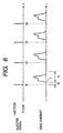
- FIG. 6 An example of the waveform of this ionic current Ii is shown in Fig. 6.
- the ionic current Ii shown in this example it rises with a some time lag td from the input timing (time of injection of fuel) tj1, tj2, tj3, tj4, .... in the injection signal commanding the fuel injection valve 33 to eject fuel.
- the waveform of ionic current Ii has a first peak followed by a second peak which is somewhat larger than the first peak. Since the time X of rise of ionic current Ii corresponds to the time of ignition of the fuel F, the time of ignition can be known from the ionic current Ii.
- the engine can be controlled.
- the conditions of combustion in the cylinder can be known also from the height of wave or peak position obtained from the waveform of ionic current or the area (integrated value) obtained from the waveform of ionic current.
- the engine 30 was actuated and warmed up.
- the engine 30 was then operated at a predetermined rotary speed Nr while the glow plug 10 was not energized.
- the surface temperature Ts of the forward end 2a of the glow plug 10 at this time was then estimated from the resistivity Rg of the ceramic heating element 4.
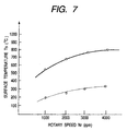
- the relationship between the engine rotary speed Nr and the surface temperature Ts is shown in Fig. 7.
- the surface temperature Ts of the forward end 2a (exposed portion 2d) of the glow plug 10 rises as the rotary speed Nr increases. Further, the greater the load L is, the higher is the surface temperature Ts.
- the glow plug 10 is preferably energized to raise the surface temperature Ts of the forward end 2a to not lower than 500°C.
- the glow plug 10 to be used in the glow plug control apparatus 100 is preferably arranged such that the resisitivity Ri of the ceramic substrate is not higher than 1 G ⁇ when the surface temperature Ts is not lower than 500°C as mentioned above.
- Ri is preferably not lower than 10 k ⁇ .
- the glow plug 10 momentarily rises to about 1,400°C but normally rises to about 1,200°C at highest. Since migration gradually occurs, it is considered that Ri may be not lower than 10 k ⁇ when Ts is not higher than 1,200°C.
- a glow plug having characteristics falling within the substrate resistivity Ri range of from 10 k ⁇ to 1 G ⁇ at a surface temperature Ts range of from 500°C to 1,200°C as encompassed by four straight lines in Fig. 3. It is made obvious that preferred among the five formulations A to E set forth in Table 1 are three formulations, i.e., B (present embodiment), C, and D.
- the resisitivity Ri of the ceramic substrate 5 can be lowered, making it easy to detect ionic current.
- the electrically-conductive ceramic has a lower durability, heat resistance or corrosion resistance than silicon nitride.
- the glow plugs comprising the ceramic substrate 5 having the foregoing formulations A to E were each subjected to energization durability test involving 30,000 repetition of cycle consisting of 1 minute of energization (momentary highest temperature of forward end: 1,400°C) and 1 minute of suspension of energization (air-cooled until ordinary temperature is reached) .
- the glow plugs having the formulations A to D showed no abnormality.
- the glow plug having the formulation E showed cracking at 6,000th to 8,000th cycle.
- the added amount of the electrically-conductive ceramic is excessively increased. Accordingly, the added amount of the electrically-conductive ceramic is preferably determined taking into account the durability of the ceramic substrate 5, etc.
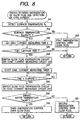
- the flow chart of control of the glow plug control apparatus 100 according to the present embodiment is shown in Fig. 8. This control is performed throughout both the stage before and after the completion of warming-up of the engine.
- the switching between the energization of glow plug and the detection of ionic current shown in this flow chart is performed for main routine (not described in detail) in ECU 105 by interrupt at proper intervals.
- main routine not described in detail
- the switch 102 is connected to the battery 101 (lower side as shown in the drawing) while the switch 103 is switched ON (circuit closed).
- ECU 105 detects the surface temperature Ts of the forward end 2a of the glow plug 10 at the step S41.
- the heating element resistivity Rg is determined from the voltage Vg applied to the glow plug 10 and the resulting current Ig.
- the surface temperature Ts is then estimated from the heating element resistivity Rg.
- step S42 it is judged whether the surface temperature Ts is not lower than 500°C. If Ts is lower than 500°C (No), i.e., if the temperature of the glow plug 10 is not sufficiently raised as in the initial stage such as pre-glow stage, the process proceeds to the step S43. At the step S43, first energization control over glow plug is conducted such that the surface temperature Ts of the forward end 2a reaches not lower than 500°C.
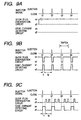
- control as shown in Fig. 9 (a) is conducted.
- the glow plug energization circuit is switched ON to energize the glow plug 10.
- the ionic current detection circuit is switched OFF so that the detection of ions is not conducted. This is intended to raise the temperature of the glow plug, which has not been sufficiently raised, as soon as possible and hence allow the actuation of the engine 30. Further, since the surface temperature Ts is low, the resisitivity Ri of the ceramic substrate 5 is too great to conduct the measurement of ionic current Ii.
- the process proceeds to the step S44 where the time ti of measuring ionic current Ii is then set.
- the time ti is selected and set depending on the engine rotary speed Nr and load L detected by ECU 105. This is intended to measure ionic current Ii for a proper period of time depending on the time lag td based on the fuel injection time tj1 or the like or the time tc of continuation of waveform of ionic current , which varies with the engine rotary speed Nr or load L (see Fig. 6).
- time ti may be read out from the engine rotary speed Nr and load L in a look-up table prepared and stored in ROM of ECU 105 by which the time ti is given.
- data substitute for load L such as accelerator opening and accelerator position may be used.
- time ti represented by a constant value e.g., 90° CA
- crank angle may be selected.
- step S45 the process proceeds to the step S45 to judge to see if it is in the fuel injection period. In some detail, detection is made to see if the injector signal from the fuel injection valve 33 is at timing tj1, tj2 .... indicating injection command (high). If the injector signal is not at the fuel injection time tj1 (No), the process returns to main routine.
- the process proceeds to the step S46 where when the injector signal is at the timing indicating injection command (high) as shown in Figs. 9B and 9C, the switches 102, 103 are operated to switch the glow plug energization circuit Off and the ionic current measuring circuit ON.
- the switch 102 is connected to the constant voltage power supply 106 (upper side as shown in the drawing) while the switch 103 is switched OFF (circuit opened). In this manner, ionic current Ii can be measured between the exposed portion 2d of the glow plug 10 and the cylinder head 31, making it possible to detect if the fuel is ignited in the engine or the time of ignition and hence help control the engine 30.
- the process further proceeds to the step S47 where an ionic currant measuring timer is allowed to start. Thereafter, at the step S48, the passage of the ionic current measurement time ti which has been set at the step S44 is awaited.
- the process proceeds to the step S49 where after the lapse of time ti from the fuel injection time tj1 or the like as shown in Figs. 9B and 9C, the switches 102, 103 are then operated to switch the ionic current measuring circuit OFF and the glow plug energization circuit ON.
- the switch 102 is connected to the battery 101 (lower side as shown in the drawing) while the switch 103 is switched ON (circuit closed). In this manner, the measurement of ionic current Ii is terminated, making it again possible to allow the ceramic heating element 4 of the glow plug 10 to generate heat.
- ECU 105 judges at the step S50 to see if the temperature Tw of water in the engine is not lower than a predetermined temperature (not lower than 60°C in the present embodiment) . In other words, it is judged to see if the engine 30 has been warmed up.
- step S51 second energization control over glow plug
- the second energization control over glow plug allows the surface temperature Ts of the forward end 2a (exposed portion 2d) of the glow plug 10 to be kept to not lower than 500°C and even raised to higher than 500°C, e.g., as high as not lower than 800°C, making it possible to continue pre-glow and after-glow operation.
- the surface temperature Ts of the glow plug 10 may be kept to a range of from 800°C to 900°C. Therefore, in the period tg, the switch 103 may be switched ON or Off as in the step S52 to control the temperature of the glow plug 10.
- step S52 the process proceeds to third energization control over glow plug (step S52) where after the lapse of time ti from the fuel injection time tj1 or the like as shown in Fig. 9C, pulse energization of the glow plug 10 is conducted such that the surface temperature Ts is kept to not lower than 500°C for a period of time tg until the subsequent fuel injection time tj2, and so on.
- the pulse energization of the glow plug 10 is conducted since the warming-up of the engine 30 has been completed to eliminate the necessity of keeping the temperature of the glow plug 10 to so high as in the pre-glow stage or after-glow stage.
- the pulse energization of the glow plug 10 suffices if the surface temperature Ts is kept to an extent such that ionic current Ii can be measured using the glow plug 10 (Ts ⁇ 500°C).
- Ts ionic current Ii can be measured using the glow plug 10
- the surface temperature of the glow plug 10 is continuously kept to an extremely high temperature, the deterioration of the glow plug 10 is accelerated.
- the surface temperature Ts is preferably lowered.
- the pulse energization of the glow plug 10 is intended to reduce the power to be consumed to energize the glow plug 10 (ceramic heating element 4), preventing the reduction of fuel economy.
- the period during which the glow plug 10 (ceramic heating element 4) is energized within the period tg is adjusted to keep the surface temperature Ts of the forward end 2d (exposed portion 2d) to not lower than a proper value of not lower than 500°C (e.g., 700°C). Accordingly, also in the subsequent processing, the surface temperature Ts is judged to be not lower than 500°C at the step S42, making it possible to alternatively continue the measurement of ionic current Ii and the heating of the glow plug 10. In this manner, the ionic current Ii thus measured can be used to control the engine 30 as well as lessen the vibration and noise and clean the exhaust gas.
- the surface temperature Ts of the forward end 2a can be not lower than 500°C (800°C at highest in the graph of Fig. 7) even if the glow plug 10 is not energized depending on the rotary speed Nr of the engine 30 or the load L on the engine 30. Accordingly, under the driving conditions such that the surface temperature Ts is raised, it is likely that the glow plug 10 cannot be energized within the period tg.
- water temperature Tw is used to make judgment. However, once the water temperature Tw exceeds a predetermined tempearture (e.g., 60°C), a flag may be set as completion of warming-up. The conditions of the flag can be used to make judgment.
- a predetermined tempearture e.g. 60°C
- the glow plug control apparatus 100 switches the switches 102, 103 to perform the energization of the glow plug and the measurement of ionic current. Accordingly, in the initial stage of pre-glow period where the surface temperature Ts is low, the glow plug 10 can be energized without measuring ionic current Ii to rapidly raise the temperature thereof. When the surface temperature Ts exceeds 500°C, the measurement of ionic current Ii is performed during a certain period of time ti from the fuel injection time tj1 or the like. After the lapse of this time ti, the energization of the glow plug 10 is controlled.
- the ignition and combustion of fuel in the engine can be accelerated by the heat generation of the glow plug 10. Further, by measuring ionic current Ii, the engine can be controlled. Moreover, even after the completion of warming-up, by keeping the surface temperature Ts of the forward end 2a (exposed portion 2d) of the glow plug 10 to not lower than 500°C, the ignition and combustion of fuel can be stabilized, making it possible to lessen the vibration and noise and clean the exhaust gas. Further, by measuring ionic current Ii, the engine can be controlled.
- the surface temperature Ts of the forward end 2a is estimated from the resistivity Rg of the ceramic heating element 4 to make detection (step S41). By judging to see if the surface temperature Ts is not lower than 500°C, it is judged (at step S42) which the process proceeds to the first energization control over glow plug (step s43) or the measurement of ionic current (step S44 and after).
- the embodiment 2 differs from the embodiment 1 only in that the resistivity Rg of the ceramic heating element 4 is used to make control but has the same configuration of glow plug 10 and glow plug control apparatus 100 as in the embodiment 1. Therefore, different parts will be described. The description of the same parts will be omitted or simplified. In the present embodiment, too, controlling is performed throughout both the stage before and after the completion of warming-up of the engine.
- Fig. 10 The control performed by the glow plug control apparatus according to the embodiment 2 is shown in Fig. 10.
- This flow chart is almost the same as the flow chart of the embodiment 1 except that the steps S41A, 42A, 51A and 52A differ from that of the embodiment 1.
- ECU 105 determines the resistivity Rg of the ceramic heating element 4 from the voltage Vg applied to the glow plug 10 and the resulting current Ig at the step S41A.
- the heating element resistivity Rg is not lower than 1,000 m ⁇ .
- the resistivity Rg of the ceramic heating element 4 there is a relationship shown in Fig. 4 between the resistivity Rg of the ceramic heating element 4 and the surface temperature Ts. Accordingly, judgment is made to see if Rg is not lower than 1,000 m ⁇ , which corresponds to Ts of not lower than 500°C. If Rg is lower than 1,000 m ⁇ (No), i.e., if the glow plug 10 has not been sufficiently heated as in the initial stage of pre-glow period, the process proceeds to the step S43. At the step S43, first energization control over glow plug is performed such that the heating element resistivity Rg not lower than 1,000 m ⁇ , i.e., the surface temperature Ts of the forward end 2a reaches not lower than 500°C.
- step S42A if Rg is not lower than 1,000 m ⁇ (Yes), the process proceeds to the step 544 and after where the measurement of ionic current Ii is then performed in the same manner as in the embodiment 1.
- step S50 determines whether the water temperature Tw is lower than 60°C (No) as a result of judgment at the step S50 to see if the temperature of water in the engine is not lower than 60°C, i.e., the engine 30 has been warmed up. Then, the process proceeds to the second energization control over glow plug (step S51A). At the step S51A, too, as shown in Fig. 9B, the energization of the glow plug 10 is continued for a period of time tg after the lapse of time ti from the fuel injection time tj1 until the subsequent fuel injection time tj2, and so on. Accordingly, the measurement of ionic current can be performed.
- the second energization control over glow plug allows the glow plug 10 to be energized, making it possible to keep the heating element resistivity Rg to not lower than 1,000 m ⁇ and even raise it to higher than 1,000 m ⁇ . In this manner, pre-glow and after-glow can be continued.
- step S52A the third energization control over glow plug
- step S52A pulse energization of the glow plug 10 is conducted such that the heating element resisitivity Rg is kept to not lower than 1,000 m ⁇ for a period of time tg until the subsequent fuel injection time tj2, and so on.
- the period during which the glow plug 10 (ceramic heating element 4) is energized within the period tg is adjusted to keep the heating element resisitivity to not lower than 1,280 m ⁇ , which corresponds to the surface temperature Ts of not lower than 700°C. Accordingly, also in the subsequent processing, the heating element resistivity Rg is judged to be not lower than 1,000 m ⁇ at the step S42A, making it possible to alternatively continue the measurement of ionic current Ii and the heating of the glow plug 10. In this manner, the ionic current Ii thus measured can be used to control the engine 30 as well as lessen the vibration and noise and clean the exhaust gas.
- the energization control over the glow plug 10 can be performed as in the embodiment 1. Further, since it is not necessary that the heating element resistivity Rg be converted to the surface temperature Ts at the step S41 or the like, processing can be performed more easily. Accordingly, in the initial stage of pre-glow period, the glow plug can be energized without measuring ionic current Ii to rapidly raise the temperature thereof. On the other hand, in the stage after pre-glow and during after-flow, the ignition and combustion of fuel in the engine can be accelerated by the heat generation of the glow plug 10. Further, by measuring ionic current Ii, the engine can be controlled.
- the heating element resistivity Rg of the glow plug 10 is kept to not lower than 1,000 m ⁇ , particularly to not lower than 1,290 m ⁇ .
- the surface temperature Ts of the forward end 2a (exposed portion 2d) can be kept to not lower than 500°C, particularly to not lower than 700°C.
- the ignition and combustion of fuel can be stabilized, making it possible to lessen the vibration and noise and clean the exhaust gas.
- feedback control over engine such as timing and amount of fuel injection can be performed.
- the voltage Vg across the positive and negative electrodes of the battery 101 varies greatly with the ambient temperature or degree of consumption, the voltage Vg measured at the voltmeter 112 is used to determine the heating element resistivity Rg.
- the third embodiment of implication of the present invention will be described hereinafter.
- the relationship between the resistivity Rg of the ceramic heating element 4 of the glow plug 10 and the surface temperature Ts of the exposed portion 2a is made the use of to perform controlling.
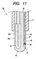
- the present embodiment is the same as the first and second embodiments except that it differs from the first and second embodiments in that a thermocouple is formed in the ceramic substrate of the glow plug separately of the ceramic heating element so that the temperature of the exposed portion can be directly measured.
- the other parts is equal to the foregoing embodiments, and different parts will be described
- the ceramic heater 42 is brazed to the outer cylinder 3.
- a U-shaped ceramic heating element 44 is provided at the forward end 42a of the ceramic heater 42.
- an R thermocouple 46 comprising lead wires 47, 48 welded at the end thereof embedded by a cement 49 is provided in a groove 43 formed axially (vertically as shown in the drawing) on the periphery of the ceramic substrate 45.
- the glow plug 40 having the foregoing configuration, when the ceramic heating element 44 is energized to generate heat, the temperature of the area having the temperature extremely close to the surface temperature Ts of the forward end 42a can be directly measured.
- the use of the glow plug 40 having the foregoing configuration makes it possible to measure the surface temperature Ts more accurately than estimated from the resistivity Rg of the ceramic heating element 4 as in the embodiment 1 in order to control the glow plug 40.
- the control over the glow plug 40 can be made in the same manner as in the embodiment 1 at the steps S41 and S42 (see Fig. 8), except that the output of R thermocouple 46 is used to determine the surface temperature Ts by which judgment is then made.
- the foregoing embodiments have been described with reference to the circuit configuration having the battery 101 as well as the constant voltage power supply 108 to be added to measure ionic current Ii (see Fig. 5).
- the resistivity Rd of the detection resistor or the resistivity Ri of the ceramic substrate 5 only the battery 101 can be used to form a circuit configuration capable of heating the glow plug 10 and measuring ionic current.
- compositions of the ceramic substrate 5 of the glow plug there were prepared the five compositions set forth in Table 1. However, it is apparent that other compositions of ceramic substrate can be used to realize the glow plug.
- Examples of the electrically-conductive ceramic employable herein include the foregoing TiN, TiC, WC, MoSi 2 and SiC, and silicide, carbide, boride and nitride of W, Ta, Nb, Ti, Zr, Hf, V and Cr such as ZrN, TaN, TiSi2, CrSi 2 and WSi 2 .
- a sintering aid there may be used Al 2 O 3 , Er 2 O 3 , V 2 O 3 , WO 3 , Y 2 O 3 or the like besides Yb 2 O 3 and Cr 2 O 3 used in the present embodiment.
Landscapes
- Engineering & Computer Science (AREA)
- Chemical & Material Sciences (AREA)
- Combustion & Propulsion (AREA)
- Mechanical Engineering (AREA)
- General Engineering & Computer Science (AREA)
- Ignition Installations For Internal Combustion Engines (AREA)
Applications Claiming Priority (4)
| Application Number | Priority Date | Filing Date | Title |
|---|---|---|---|
| JP2000079844 | 2000-03-22 | ||
| JP2000079844 | 2000-03-22 | ||
| JP2001058157 | 2001-03-02 | ||
| JP2001058157A JP2001336468A (ja) | 2000-03-22 | 2001-03-02 | グロープラグ制御装置、グロープラグ、及びエンジンの燃焼室内のイオン検出方法 |
Publications (3)
| Publication Number | Publication Date |
|---|---|
| EP1136697A2 true EP1136697A2 (fr) | 2001-09-26 |
| EP1136697A3 EP1136697A3 (fr) | 2005-02-16 |
| EP1136697B1 EP1136697B1 (fr) | 2007-06-27 |
Family
ID=26588042
Family Applications (1)
| Application Number | Title | Priority Date | Filing Date |
|---|---|---|---|
| EP01302648A Expired - Lifetime EP1136697B1 (fr) | 2000-03-22 | 2001-03-22 | Appareil de commande de bougie à incandescence , bougie, et méthode pour détecter des ions dans la chambre de combustion d'un moteur |
Country Status (4)
| Country | Link |
|---|---|
| US (1) | US6414273B1 (fr) |
| EP (1) | EP1136697B1 (fr) |
| JP (1) | JP2001336468A (fr) |
| DE (1) | DE60129065T2 (fr) |
Cited By (8)
| Publication number | Priority date | Publication date | Assignee | Title |
|---|---|---|---|---|
| DE10162253A1 (de) * | 2001-12-18 | 2003-07-10 | Daimler Chrysler Ag | Glüh- und Ionenstrommeßvorrichtung für einen Dieselmotor |
| WO2010056411A1 (fr) * | 2008-11-17 | 2010-05-20 | Federal-Mogul Ignition Company | Bougie de préchauffage munie d’une sonde d’élément chauffant métallique |
| EP3046395A1 (fr) * | 2015-01-16 | 2016-07-20 | NGK Spark Plug Co., Ltd. | Appareil de chauffage, appareil d'évaluation de la température et appareil de commande de dispositif de chauffage |
| EP3045714A1 (fr) * | 2015-01-16 | 2016-07-20 | NGK Spark Plug Company Limited | Appareil de mesure de courant ionique |
| EP3096000A3 (fr) * | 2015-05-18 | 2016-12-21 | NGK Spark Plug Co., Ltd. | Dispositif de chauffage, dispositif d'estimation de l'état d'un dispositif de chauffage et procédé d'estimation de l'état d'un dispositif de chauffage |
| CN114263535A (zh) * | 2021-12-14 | 2022-04-01 | 西安现代控制技术研究所 | 一种有效提高微型涡喷发动机点火可靠性的方法 |
| US12031513B2 (en) | 2020-11-18 | 2024-07-09 | Pratt & Whitney Canada Corp. | Method and system for glow plug operation |
| EP4001631B1 (fr) * | 2020-11-18 | 2025-03-05 | Pratt & Whitney Canada Corp. | Procédé et système pour opération de bougie de préchauffage |
Families Citing this family (25)
| Publication number | Priority date | Publication date | Assignee | Title |
|---|---|---|---|---|
| DE19959766A1 (de) * | 1999-12-11 | 2001-06-13 | Bosch Gmbh Robert | Glühstiftkerze |
| DE10128656A1 (de) * | 2001-06-15 | 2003-01-02 | Beru Ag | Stabglühkerze und Verfahren zu ihrer Herstellung |
| JP3886449B2 (ja) * | 2002-12-26 | 2007-02-28 | 日本特殊陶業株式会社 | グロープラグ及びグロープラグの取付け構造 |
| EP1612486B1 (fr) * | 2004-06-29 | 2015-05-20 | Ngk Spark Plug Co., Ltd | Bougie à incandesence |
| US7325697B2 (en) * | 2005-02-02 | 2008-02-05 | Seville Classics, Inc. | Storage bin for use with shelving system |
| US7470875B1 (en) * | 2005-12-16 | 2008-12-30 | Locust Usa, Inc. | Ignitor plug |
| DE102006060632A1 (de) * | 2006-12-21 | 2008-06-26 | Robert Bosch Gmbh | Verfahren zur Regelung der Temperatur einer Glühkerze einer Brennkraftmaschine |
| JP4780056B2 (ja) * | 2007-08-01 | 2011-09-28 | 株式会社デンソー | グロープラグ劣化判定装置 |
| JP4939342B2 (ja) * | 2007-08-24 | 2012-05-23 | 日本特殊陶業株式会社 | グロープラグ及びグロープラグ制御システム |
| WO2009028307A1 (fr) * | 2007-08-24 | 2009-03-05 | Ngk Spark Plug Co., Ltd. | Bougie incandescente et système de commande de bougie incandescente |
| JP4939343B2 (ja) * | 2007-08-24 | 2012-05-23 | 日本特殊陶業株式会社 | グロープラグ |
| WO2009057597A1 (fr) * | 2007-10-29 | 2009-05-07 | Kyocera Corporation | Elément chauffant en céramique et bougie de préchauffage équipée de l'élément chauffant |
| JP5292317B2 (ja) * | 2008-02-20 | 2013-09-18 | 日本特殊陶業株式会社 | セラミックヒータ及びグロープラグ |
| JP5027027B2 (ja) * | 2008-03-24 | 2012-09-19 | 日本特殊陶業株式会社 | グロープラグ |
| JP5027026B2 (ja) * | 2008-03-24 | 2012-09-19 | 日本特殊陶業株式会社 | グロープラグ |
| US8022337B2 (en) * | 2008-06-10 | 2011-09-20 | Locust, Usa, Inc. | Ignitor plug assembly |
| GB2464128B (en) * | 2008-10-02 | 2013-07-31 | Gm Global Tech Operations Inc | Method for controlling a glow plug of a combustion machine of a vehicle and controller for a glow plug of combustion machine of a vehicle |
| JP5660612B2 (ja) | 2011-01-12 | 2015-01-28 | ボッシュ株式会社 | グロープラグ先端温度推定方法及びグロープラグ駆動制御装置 |
| JP5899621B2 (ja) * | 2011-02-04 | 2016-04-06 | トヨタ自動車株式会社 | 内燃機関のグロープラグ制御装置 |
| WO2013042488A1 (fr) * | 2011-09-20 | 2013-03-28 | ボッシュ株式会社 | Procédé de diagnostic de bougie incandescente et dispositif de diagnostic de bougie incandescente |
| DE102011085435A1 (de) * | 2011-10-28 | 2013-05-02 | Robert Bosch Gmbh | Verfahren und Vorrichtung zur Bestimmung einer Oberflächentemperatur einer Glühstiftkerze in einem Verbrennungsmotor |
| JP6271915B2 (ja) * | 2013-08-28 | 2018-01-31 | 日本特殊陶業株式会社 | 燃焼圧センサ付きグロープラグ及びセンサ無しグロープラグを装着した内燃機関 |
| JP2017032492A (ja) | 2015-08-05 | 2017-02-09 | トヨタ自動車株式会社 | 内燃機関の制御装置 |
| JP6667327B2 (ja) * | 2016-03-17 | 2020-03-18 | 日本特殊陶業株式会社 | 加熱装置及び温度推定装置 |
| DE102016114929B4 (de) * | 2016-08-11 | 2018-05-09 | Borgwarner Ludwigsburg Gmbh | Druckmessglühkerze |
Citations (2)
| Publication number | Priority date | Publication date | Assignee | Title |
|---|---|---|---|---|
| JPH109113A (ja) | 1996-06-26 | 1998-01-13 | Denso Corp | イオン電流検出装置 |
| JPH1077945A (ja) | 1996-04-10 | 1998-03-24 | Denso Corp | イオン電流検出装置及びそれに用いられるグロープラグ |
Family Cites Families (8)
| Publication number | Priority date | Publication date | Assignee | Title |
|---|---|---|---|---|
| BR9700466A (pt) * | 1996-03-29 | 1998-11-03 | Ngk Spark Plug Co | Aquecedor cerâmico |
| JP3704869B2 (ja) * | 1996-06-10 | 2005-10-12 | 株式会社デンソー | グロープラグ、グロープラグを用いたイオン電流検出装置、及びグロープラグの製造方法 |
| JP3605989B2 (ja) * | 1996-06-26 | 2004-12-22 | 株式会社デンソー | イオン電流検出装置 |
| US5809957A (en) * | 1996-06-12 | 1998-09-22 | Caterpillar Inc. | Method of prolonging the life of glow plugs |
| JP3796846B2 (ja) * | 1996-09-12 | 2006-07-12 | 株式会社デンソー | グロープラグ |
| JP3605965B2 (ja) | 1996-09-12 | 2004-12-22 | 株式会社デンソー | グロープラグ |
| DE19852485C2 (de) * | 1998-11-13 | 2002-09-19 | Beru Ag | Glühkerze und Steckanschluss für eine Glühkerze |
| DE10028073C2 (de) * | 2000-06-07 | 2003-04-10 | Beru Ag | Verfahren und Schaltungsanordnung zum Aufheizen einer Glühkerze |
-
2001
- 2001-03-02 JP JP2001058157A patent/JP2001336468A/ja active Pending
- 2001-03-22 EP EP01302648A patent/EP1136697B1/fr not_active Expired - Lifetime
- 2001-03-22 US US09/813,931 patent/US6414273B1/en not_active Expired - Lifetime
- 2001-03-22 DE DE60129065T patent/DE60129065T2/de not_active Expired - Lifetime
Patent Citations (2)
| Publication number | Priority date | Publication date | Assignee | Title |
|---|---|---|---|---|
| JPH1077945A (ja) | 1996-04-10 | 1998-03-24 | Denso Corp | イオン電流検出装置及びそれに用いられるグロープラグ |
| JPH109113A (ja) | 1996-06-26 | 1998-01-13 | Denso Corp | イオン電流検出装置 |
Cited By (11)
| Publication number | Priority date | Publication date | Assignee | Title |
|---|---|---|---|---|
| DE10162253A1 (de) * | 2001-12-18 | 2003-07-10 | Daimler Chrysler Ag | Glüh- und Ionenstrommeßvorrichtung für einen Dieselmotor |
| EP1329630A3 (fr) * | 2001-12-18 | 2006-03-01 | Beru AG | Dispositif de préchauffage et de mesure de courant ionique pour un moteur Diesel |
| WO2010056411A1 (fr) * | 2008-11-17 | 2010-05-20 | Federal-Mogul Ignition Company | Bougie de préchauffage munie d’une sonde d’élément chauffant métallique |
| EP3046395A1 (fr) * | 2015-01-16 | 2016-07-20 | NGK Spark Plug Co., Ltd. | Appareil de chauffage, appareil d'évaluation de la température et appareil de commande de dispositif de chauffage |
| EP3045714A1 (fr) * | 2015-01-16 | 2016-07-20 | NGK Spark Plug Company Limited | Appareil de mesure de courant ionique |
| EP3171018A1 (fr) * | 2015-01-16 | 2017-05-24 | NGK Spark Plug Co., Ltd. | Appareil de mesure de courant ionique |
| EP3096000A3 (fr) * | 2015-05-18 | 2016-12-21 | NGK Spark Plug Co., Ltd. | Dispositif de chauffage, dispositif d'estimation de l'état d'un dispositif de chauffage et procédé d'estimation de l'état d'un dispositif de chauffage |
| US12031513B2 (en) | 2020-11-18 | 2024-07-09 | Pratt & Whitney Canada Corp. | Method and system for glow plug operation |
| EP4001631B1 (fr) * | 2020-11-18 | 2025-03-05 | Pratt & Whitney Canada Corp. | Procédé et système pour opération de bougie de préchauffage |
| CN114263535A (zh) * | 2021-12-14 | 2022-04-01 | 西安现代控制技术研究所 | 一种有效提高微型涡喷发动机点火可靠性的方法 |
| CN114263535B (zh) * | 2021-12-14 | 2023-11-14 | 西安现代控制技术研究所 | 一种有效提高微型涡喷发动机点火可靠性的方法 |
Also Published As
| Publication number | Publication date |
|---|---|
| EP1136697A3 (fr) | 2005-02-16 |
| US20020043524A1 (en) | 2002-04-18 |
| DE60129065T2 (de) | 2008-02-28 |
| DE60129065D1 (de) | 2007-08-09 |
| JP2001336468A (ja) | 2001-12-07 |
| US6414273B1 (en) | 2002-07-02 |
| EP1136697B1 (fr) | 2007-06-27 |
Similar Documents
| Publication | Publication Date | Title |
|---|---|---|
| US6414273B1 (en) | Glow plug control apparatus, glow plug, and method of detecting ions in engine combustion chamber | |
| US6635851B2 (en) | Process and circuit for heating up a glow plug | |
| EP0834652B1 (fr) | Bougie de prechauffage, son procede de fabrication, et detecteur de courant ionique | |
| JP4956486B2 (ja) | グロープラグ通電制御装置及びグロープラグ通電制御システム | |
| EP1447560A1 (fr) | Dispositif et mèthode de contrôle d'excitation de bougie à incandescence | |
| JP4723192B2 (ja) | グロープラグ通電制御装置及びグロープラグ通電制御方法 | |
| US6111223A (en) | Ceramic glow plug having portion of heater within metallic sleeve | |
| JP4047762B2 (ja) | グロープラグの制御装置 | |
| JP2002257779A (ja) | ガス濃度センサのヒータ制御装置 | |
| JP4723174B2 (ja) | グロープラグ通電制御装置及びグロープラグ通電制御方法 | |
| JP2003527553A (ja) | シース形グロープラグ | |
| KR100670574B1 (ko) | 시이드형 글로우 플러그 | |
| US6188049B1 (en) | Apparatus and method for controlling heater of air-fuel ratio sensor in internal combustion engine | |
| JP3785699B2 (ja) | グロープラグ | |
| JP4972035B2 (ja) | グロープラグ通電制御装置及びグロープラグ通電制御システム | |
| JP3605990B2 (ja) | イオン電流検出装置及びそれに用いられるグロープラグ | |
| EP3046395B1 (fr) | Appareil de chauffage, appareil d'évaluation de la température et appareil de commande de dispositif de chauffage | |
| JP4094205B2 (ja) | セラミックヒータ又はグロープラグの特性測定方法 | |
| JP3785698B2 (ja) | グロープラグ | |
| JPH1182271A (ja) | ディーゼルエンジンの異常検出装置 | |
| JP2001295744A (ja) | イオン電流検出装置 | |
| JP3823394B2 (ja) | グロープラグ | |
| JP4174335B2 (ja) | グロープラグ通電制御装置及びグロープラグ通電制御方法 | |
| US6890170B2 (en) | Heater with glow plug/flame monitor | |
| EP3171018B1 (fr) | Appareil de mesure de courant ionique |
Legal Events
| Date | Code | Title | Description |
|---|---|---|---|
| PUAI | Public reference made under article 153(3) epc to a published international application that has entered the european phase |
Free format text: ORIGINAL CODE: 0009012 |
|
| AK | Designated contracting states |
Kind code of ref document: A2 Designated state(s): AT BE CH CY DE DK ES FI FR GB GR IE IT LI LU MC NL PT SE TR |
|
| AX | Request for extension of the european patent |
Free format text: AL;LT;LV;MK;RO;SI |
|
| PUAL | Search report despatched |
Free format text: ORIGINAL CODE: 0009013 |
|
| AK | Designated contracting states |
Kind code of ref document: A3 Designated state(s): AT BE CH CY DE DK ES FI FR GB GR IE IT LI LU MC NL PT SE TR |
|
| AX | Request for extension of the european patent |
Extension state: AL LT LV MK RO SI |
|
| 17P | Request for examination filed |
Effective date: 20050408 |
|
| 17Q | First examination report despatched |
Effective date: 20050701 |
|
| AKX | Designation fees paid |
Designated state(s): DE FR GB IT |
|
| GRAP | Despatch of communication of intention to grant a patent |
Free format text: ORIGINAL CODE: EPIDOSNIGR1 |
|
| GRAS | Grant fee paid |
Free format text: ORIGINAL CODE: EPIDOSNIGR3 |
|
| GRAA | (expected) grant |
Free format text: ORIGINAL CODE: 0009210 |
|
| AK | Designated contracting states |
Kind code of ref document: B1 Designated state(s): DE FR GB IT |
|
| REG | Reference to a national code |
Ref country code: GB Ref legal event code: FG4D |
|
| REF | Corresponds to: |
Ref document number: 60129065 Country of ref document: DE Date of ref document: 20070809 Kind code of ref document: P |
|
| ET | Fr: translation filed | ||
| PLBI | Opposition filed |
Free format text: ORIGINAL CODE: 0009260 |
|
| 26 | Opposition filed |
Opponent name: BERU AG Effective date: 20080314 |
|
| PG25 | Lapsed in a contracting state [announced via postgrant information from national office to epo] |
Ref country code: IT Free format text: LAPSE BECAUSE OF FAILURE TO SUBMIT A TRANSLATION OF THE DESCRIPTION OR TO PAY THE FEE WITHIN THE PRESCRIBED TIME-LIMIT Effective date: 20070627 |
|
| PLAX | Notice of opposition and request to file observation + time limit sent |
Free format text: ORIGINAL CODE: EPIDOSNOBS2 |
|
| PLBB | Reply of patent proprietor to notice(s) of opposition received |
Free format text: ORIGINAL CODE: EPIDOSNOBS3 |
|
| GBPC | Gb: european patent ceased through non-payment of renewal fee |
Effective date: 20080322 |
|
| PLAB | Opposition data, opponent's data or that of the opponent's representative modified |
Free format text: ORIGINAL CODE: 0009299OPPO |
|
| R26 | Opposition filed (corrected) |
Opponent name: BERU AG Effective date: 20080314 |
|
| PLAB | Opposition data, opponent's data or that of the opponent's representative modified |
Free format text: ORIGINAL CODE: 0009299OPPO |
|
| PG25 | Lapsed in a contracting state [announced via postgrant information from national office to epo] |
Ref country code: GB Free format text: LAPSE BECAUSE OF NON-PAYMENT OF DUE FEES Effective date: 20080322 |
|
| PLCK | Communication despatched that opposition was rejected |
Free format text: ORIGINAL CODE: EPIDOSNREJ1 |
|
| APAH | Appeal reference modified |
Free format text: ORIGINAL CODE: EPIDOSCREFNO |
|
| APBM | Appeal reference recorded |
Free format text: ORIGINAL CODE: EPIDOSNREFNO |
|
| APBP | Date of receipt of notice of appeal recorded |
Free format text: ORIGINAL CODE: EPIDOSNNOA2O |
|
| APBQ | Date of receipt of statement of grounds of appeal recorded |
Free format text: ORIGINAL CODE: EPIDOSNNOA3O |
|
| APBU | Appeal procedure closed |
Free format text: ORIGINAL CODE: EPIDOSNNOA9O |
|
| PLBN | Opposition rejected |
Free format text: ORIGINAL CODE: 0009273 |
|
| STAA | Information on the status of an ep patent application or granted ep patent |
Free format text: STATUS: OPPOSITION REJECTED |
|
| 27O | Opposition rejected |
Effective date: 20110112 |
|
| REG | Reference to a national code |
Ref country code: FR Ref legal event code: PLFP Year of fee payment: 15 |
|
| PGFP | Annual fee paid to national office [announced via postgrant information from national office to epo] |
Ref country code: FR Payment date: 20150309 Year of fee payment: 15 |
|
| PGFP | Annual fee paid to national office [announced via postgrant information from national office to epo] |
Ref country code: DE Payment date: 20160315 Year of fee payment: 16 |
|
| REG | Reference to a national code |
Ref country code: FR Ref legal event code: ST Effective date: 20161130 |
|
| PG25 | Lapsed in a contracting state [announced via postgrant information from national office to epo] |
Ref country code: FR Free format text: LAPSE BECAUSE OF NON-PAYMENT OF DUE FEES Effective date: 20160331 |
|
| REG | Reference to a national code |
Ref country code: DE Ref legal event code: R119 Ref document number: 60129065 Country of ref document: DE |
|
| PG25 | Lapsed in a contracting state [announced via postgrant information from national office to epo] |
Ref country code: DE Free format text: LAPSE BECAUSE OF NON-PAYMENT OF DUE FEES Effective date: 20171003 |