EP4001631B1 - Procédé et système pour opération de bougie de préchauffage - Google Patents
Procédé et système pour opération de bougie de préchauffage Download PDFInfo
- Publication number
- EP4001631B1 EP4001631B1 EP21208855.3A EP21208855A EP4001631B1 EP 4001631 B1 EP4001631 B1 EP 4001631B1 EP 21208855 A EP21208855 A EP 21208855A EP 4001631 B1 EP4001631 B1 EP 4001631B1
- Authority
- EP
- European Patent Office
- Prior art keywords
- glow plug
- voltage
- gpl
- current
- threshold
- Prior art date
- Legal status (The legal status is an assumption and is not a legal conclusion. Google has not performed a legal analysis and makes no representation as to the accuracy of the status listed.)
- Active
Links
Images


Classifications
-
- F—MECHANICAL ENGINEERING; LIGHTING; HEATING; WEAPONS; BLASTING
- F02—COMBUSTION ENGINES; HOT-GAS OR COMBUSTION-PRODUCT ENGINE PLANTS
- F02C—GAS-TURBINE PLANTS; AIR INTAKES FOR JET-PROPULSION PLANTS; CONTROLLING FUEL SUPPLY IN AIR-BREATHING JET-PROPULSION PLANTS
- F02C7/00—Features, components parts, details or accessories, not provided for in, or of interest apart form groups F02C1/00 - F02C6/00; Air intakes for jet-propulsion plants
- F02C7/26—Starting; Ignition
- F02C7/264—Ignition
- F02C7/266—Electric
-
- F—MECHANICAL ENGINEERING; LIGHTING; HEATING; WEAPONS; BLASTING
- F02—COMBUSTION ENGINES; HOT-GAS OR COMBUSTION-PRODUCT ENGINE PLANTS
- F02C—GAS-TURBINE PLANTS; AIR INTAKES FOR JET-PROPULSION PLANTS; CONTROLLING FUEL SUPPLY IN AIR-BREATHING JET-PROPULSION PLANTS
- F02C9/00—Controlling gas-turbine plants; Controlling fuel supply in air- breathing jet-propulsion plants
-
- F—MECHANICAL ENGINEERING; LIGHTING; HEATING; WEAPONS; BLASTING
- F02—COMBUSTION ENGINES; HOT-GAS OR COMBUSTION-PRODUCT ENGINE PLANTS
- F02P—IGNITION, OTHER THAN COMPRESSION IGNITION, FOR INTERNAL-COMBUSTION ENGINES; TESTING OF IGNITION TIMING IN COMPRESSION-IGNITION ENGINES
- F02P19/00—Incandescent ignition, e.g. during starting of internal combustion engines; Combination of incandescent and spark ignition
- F02P19/02—Incandescent ignition, e.g. during starting of internal combustion engines; Combination of incandescent and spark ignition electric, e.g. layout of circuits of apparatus having glowing plugs
- F02P19/021—Incandescent ignition, e.g. during starting of internal combustion engines; Combination of incandescent and spark ignition electric, e.g. layout of circuits of apparatus having glowing plugs characterised by power delivery controls
-
- F—MECHANICAL ENGINEERING; LIGHTING; HEATING; WEAPONS; BLASTING
- F02—COMBUSTION ENGINES; HOT-GAS OR COMBUSTION-PRODUCT ENGINE PLANTS
- F02P—IGNITION, OTHER THAN COMPRESSION IGNITION, FOR INTERNAL-COMBUSTION ENGINES; TESTING OF IGNITION TIMING IN COMPRESSION-IGNITION ENGINES
- F02P19/00—Incandescent ignition, e.g. during starting of internal combustion engines; Combination of incandescent and spark ignition
- F02P19/02—Incandescent ignition, e.g. during starting of internal combustion engines; Combination of incandescent and spark ignition electric, e.g. layout of circuits of apparatus having glowing plugs
- F02P19/025—Incandescent ignition, e.g. during starting of internal combustion engines; Combination of incandescent and spark ignition electric, e.g. layout of circuits of apparatus having glowing plugs with means for determining glow plug temperature or glow plug resistance
-
- F—MECHANICAL ENGINEERING; LIGHTING; HEATING; WEAPONS; BLASTING
- F23—COMBUSTION APPARATUS; COMBUSTION PROCESSES
- F23Q—IGNITION; EXTINGUISHING-DEVICES
- F23Q7/00—Incandescent ignition; Igniters using electrically-produced heat, e.g. lighters for cigarettes; Electrically-heated glowing plugs
-
- F—MECHANICAL ENGINEERING; LIGHTING; HEATING; WEAPONS; BLASTING
- F05—INDEXING SCHEMES RELATING TO ENGINES OR PUMPS IN VARIOUS SUBCLASSES OF CLASSES F01-F04
- F05D—INDEXING SCHEME FOR ASPECTS RELATING TO NON-POSITIVE-DISPLACEMENT MACHINES OR ENGINES, GAS-TURBINES OR JET-PROPULSION PLANTS
- F05D2240/00—Components
- F05D2240/35—Combustors or associated equipment
-
- F—MECHANICAL ENGINEERING; LIGHTING; HEATING; WEAPONS; BLASTING
- F05—INDEXING SCHEMES RELATING TO ENGINES OR PUMPS IN VARIOUS SUBCLASSES OF CLASSES F01-F04
- F05D—INDEXING SCHEME FOR ASPECTS RELATING TO NON-POSITIVE-DISPLACEMENT MACHINES OR ENGINES, GAS-TURBINES OR JET-PROPULSION PLANTS
- F05D2260/00—Function
- F05D2260/99—Ignition, e.g. ignition by warming up of fuel or oxidizer in a resonant acoustic cavity
-
- F—MECHANICAL ENGINEERING; LIGHTING; HEATING; WEAPONS; BLASTING
- F05—INDEXING SCHEMES RELATING TO ENGINES OR PUMPS IN VARIOUS SUBCLASSES OF CLASSES F01-F04
- F05D—INDEXING SCHEME FOR ASPECTS RELATING TO NON-POSITIVE-DISPLACEMENT MACHINES OR ENGINES, GAS-TURBINES OR JET-PROPULSION PLANTS
- F05D2270/00—Control
- F05D2270/30—Control parameters, e.g. input parameters
- F05D2270/303—Temperature
Definitions
- the application relates generally to glow plugs and, more particularly, to temperature management of a glow plug in operation.
- Glow plugs are commonly used to ignite a mixture of air and fuel in a combustor of gas turbine engines.
- glow plugs have drawbacks. For instance, the glow plugs have been known to achieve less than full reliability in conditions such as when the fuel and the engine are very cold or when the environment gets too hot. Cost is also a factor. There is always room for improvement.
- US 6,635,851 discloses a process and a circuit for heating up a glow plug.
- DE 10 2008 002574 discloses a glow plug controlling method for a diesel engine of a motor vehicle.
- a glow plug system and a method for operating a glow plug.
- the glow plug is used to ignite an engine, such as a gas turbine engine.
- the glow plug may be used for any type of application requiring such a heating element.
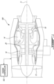
- Fig. 1 illustrates a gas turbine engine 10 of a type provided for use in subsonic flight, generally comprising in serial flow communication a fan 12 through which ambient air is propelled, a compressor section 14 for pressurizing the air, a combustor 16 in which the compressed air is mixed with fuel and ignited for generating an annular stream of hot combustion gases, and a turbine section 18 for extracting energy from the combustion gases.
- the fan 12, the compressor section 14, and the turbine section 18 rotate about a central axis 11.
- the combustor 16 defines at least one aperture 20 for receiving at least one glow plug 200 ( Fig. 2 ) for igniting the mixture of compressed air and fuel.
- Control of the operation of the engine 100 can be effected by one or more control systems, for example an engine controller 102, which is communicatively coupled to the engine 100.
- the engine controller 102 can modulate a fuel flow provided to the engine 100, the position and orientation of variable geometry mechanisms within the engine 100, a bleed level of the engine 100, and the like, based on predetermined schedules or algorithms.
- the engine controller 102 includes one or more FADEC(s), electronic engine controller(s) (EEC(s)), or the like, that are programmed to control the operation of the engine 100.
- the operation of the engine 100 can be controlled by way of one or more actuators, mechanical linkages, hydraulic systems, and the like.
- the engine controller 102 can be coupled to the actuators, mechanical linkages, hydraulic systems, and the like, in any suitable fashion for effecting control of the engine 100.
- the gas turbine engine 100 may alternatively be any other type of engine for which a glow plug may be used for ignition, for example a turboshaft engine or a turboprop engine.
- a turboshaft engine or a turboprop engine may also apply.
- the engine 100 may be for flight applications, industrial applications, or the like.
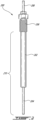
- the glow plug 200 has a body 202 and a glowing end 204 extending from the body 202.
- the glowing end 204 becomes hot during use to ignite the mixture of gas and air.
- the body 202 may define a threaded portion 206 to be threadingly engaged to the aperture 20 defined through the combustor 16 of the engine 100.
- the glow plug 200 has a connecting end 208 opposite to the glowing end 204 for connection to a source of power.
- the constant resistance component R c is generally very low.
- the resistor temperature coefficient ⁇ is constant from one glow plug to another having been made with a same manufacturing process and materials, and differs from one glow plug to another having been made from different manufacturing processes and/or different materials.
- the constant resistance component R c may vary between acceptable limits from one glow plug to another having been made with a same manufacturing process and materials.
- a glow plug system 300 The glow plug 200 is powered by a glow plug power source 302, which may be a power supply, a battery, or any other device capable of providing at least two fixed voltage levels to the glow plug 200.
- a glow plug controller 304 is coupled to the glow plug power source 302 and applies a glow plug temperature control strategy that uses the glow plug current I GPL flowing into the glow plug 200 as a temperature detection mechanism and adapts the glow plug voltage V GPL applied to the glow plug 200 by the glow plug power source 302 accordingly.
- the total glow plug resistance R will be constant for a given temperature T. If the glow plug 200 is powered with a first, nominal constant voltage V N , then the glow plug current I GPL at the minimum threshold temperature T1, will be a first value Ix. Threshold I 1 should be set at a value that corresponds to Ix, to account for effects that might decrease the resistance and thereby increase current, such as plug to plug variation and external cooling effects. Similarly, if the glow plug 200 is powered with V N at a maximum threshold temperature T2 (which can be higher than T1), then the glow plug current I GPL will be a second value ly.
- Threshold I 2 should be set at a value that corresponds to ly, to account for effects that might increase the resistance and thereby decrease current, such as plug to plug variation and external heating effects. As long as the glow plug current I GPL is kept within I 1 and I 2 , the glow plug temperature T will be protected from overheating.
- the glow plug controller 304 is configured to monitor the glow plug current I GPL and to make a control decision based on the glow plug current I GPL . There are three possible actions, depending on the value of the glow plug current I GPL . When the glow plug current is between an upper threshold I 1 and a lower threshold I 2 , a nominal voltage V N is applied to the glow plug 200 by the glow plug power source 302. If the nominal voltage V N is already applied to the glow plug 200, then V N is maintained.
- substantially no voltage encompasses applying a very low voltage, such as 0.1 V or another low value having a substantially same effect as applying zero volts.
- the difference between the upper threshold I 1 and the lower threshold I 2 is less than or equal to a given percentage of the current I 1 , such as 50%.
- the upper threshold I 1 is set to 4 A and the lower threshold I 2 is set to 2 A, such that the difference is 2 A, which is 50% of I 1 .
- the upper and lower thresholds are set so as to have a given difference, such as 3 A, 2 A, 1 A, 0.5 A, 0.25 A, 0.1 A, or 0.05 A. Other embodiments may also apply depending on practical implementations, according to the enclosed claims.
- the upper and lower current thresholds I 4 , I 2 are selected based on a predicted resistance of the glow plug 200 at a desired threshold temperature T1, T2, respectively. In some other embodiments, the upper and lower current thresholds I 1 , I 2 are selected based on a predicted current at target temperatures (which may differ from the threshold temperatures T1, T2), for example this might be used if some margin relative to the maximum and minimum temperature limits is desired.
- all voltage levels i.e. V N , V H and substantially zero volts are applied through the glow plug power source 302.
- the glow plug controller 304 may instruct the glow plug power source 302 to apply V N , V H or 0 volts (i.e. no voltage) as a function of the monitored glow plug current I GPL .
- the glow plug power source 302 is operable only at V N and another power source 306 is operable at V H .
- the glow plug power source 302 may be an on/off type power source that toggles between V N and substantially zero volts
- the glow plug power source 306 may be an on/off type power source that toggles between V H and substantially zero volts.
- the glow plug power source 302 remains on even when the glow plug power source 306 is turned on, such that toggling the glow plug power source 306 on/off causes the glow plug voltage V GPL to toggle between V H and V N .
- applying the higher voltage V H to increase the glow plug temperature T comprises toggling between the voltage V H and the voltage V N in order to ensure that the current observed at V N can be periodically compared to thresholds I1 and I2 and the glow plug temperature T increases in a controlled manner and remains under control. Toggling may be done pseudo-randomly or at a given rate with a fixed pulse duration until the monitored glow plug current I GPL measured at V N falls below the upper threshold I 1 .
- toggling between V H and V N comprises instructing the glow plug power source 302 to alternatively apply V H and V N .
- toggling between V H and V N comprises turning the glow plug power source 306 on/off repeatedly while maintaining the glow plug power source 302 on. Other embodiments may also apply.
- substantially zero volts is applied to the glow plug 200 for a pre-determined or estimated amount of time in order to cause the temperature T to decrease.
- applying substantially no voltage to the glow plug 200 may, in some embodiments, comprise toggling between substantially no voltage and V N in order to periodically compare the current at V N with thresholds I 1 and I 2 , to ensure that the glow plug temperature decreases in a controlled manner and does not get too hot. This helps to ensure that the glow plug life exceeds an expected minimum number of cycles and expected minimum total duration of operation.
- toggling may be performed pseudo-randomly or using a given rate with a fixed pulse duration until the monitored glow plug current I GPL exceeds the lower threshold I 2 when V N is applied.
- toggling between substantially zero volts and V N comprises instructing the glow plug power source 302 to alternately apply no voltage and V N .
- toggling between substantially zero volts and V N comprises turning the power source 302 on/off repeatedly while maintaining the glow plug power source 306 off. Other embodiments may also apply.
- FIG. 4 there is illustrated a specific and non-limiting example for implementation of the glow plug system 300.
- a glow plug 400 is operatively coupled to a glow plug power supply 402.
- An on/off external control turns the power supply 402 on and off.
- Three resistors R1, R2, R3 are connected in series between the glow plug power supply 402 and ground, and are used to set the output voltage V out of the power supply 402, where V out ⁇ R B R A
- V out may be set to V N or V H .
- V out V H
- V out V N
- switch 408 is on (i.e. closed)
- V GPL V out
- switch 408 is off (i.e. opened)
- V GPL 0. Therefore, the various configurations of switches 408, 414 cause V GPL to be set to any one of V N , V H , and substantially zero V.
- a current sensor 404 monitors the glow plug current I GPL flowing into the glow plug 400.
- the glow plug assembly 300 may be implemented in various ways and that the example of Fig. 4 is one such way.
- the glow plug controller 304 is implemented in one or more computing device 500, as illustrated in Fig. 5 .
- the controller 304 can be implemented as part of a full-authority digital engine controls (FADEC) or other similar device, including electronic engine control (EEC), engine control unit (ECU), avionics or cockpit equipment, electronic propeller control, propeller control unit, and the like.
- the controller 304 is implemented as part of the engine controller 102, in part or in whole. In this manner, operation of the glow plug may be managed by an engine control system. Other embodiments may also apply.
- the computing device 500 comprises a processing unit 502 and a memory 504 which has stored therein computer-executable instructions 506.
- the processing unit 502 may comprise any suitable devices configured to implement the method XX such that instructions 506, when executed by the computing device 500 or other programmable apparatus, may cause the functions/acts/steps performed as part of a method 600 as described in Fig. 6 to be executed.
- the processing unit 502 may comprise, for example, any type of general-purpose microprocessor or microcontroller, a digital signal processing (DSP) processor, a central processing unit (CPU), an integrated circuit, a field programmable gate array (FPGA), a reconfigurable processor, other suitably programmed or programmable logic circuits, or any combination thereof.
- DSP digital signal processing
- CPU central processing unit
- FPGA field programmable gate array
- reconfigurable processor other suitably programmed or programmable logic circuits, or any combination thereof.
- the memory 504 may comprise any suitable known or other machine-readable storage medium.
- the memory 504 may comprise non-transitory computer readable storage medium, for example, but not limited to, an electronic, magnetic, optical, electromagnetic, infrared, or semiconductor system, apparatus, or device, or any suitable combination of the foregoing.
- the memory 504 may include a suitable combination of any type of computer memory that is located either internally or externally to device, for example random-access memory (RAM), read-only memory (ROM), compact disc read-only memory (CDROM), electro-optical memory, magnetooptical memory, erasable programmable read-only memory (EPROM), and electrically-erasable programmable read-only memory (EEPROM), Ferroelectric RAM (FRAM) or the like.
- Memory 504 may comprise any storage means (e.g., devices) suitable for retrievably storing machine-readable instructions 506 executable by processing unit 502.
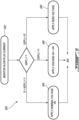
- a method 600 of operating a glow plug is described.
- the glow plug current I GPL is monitored.
- a nominal voltage V N is continuously applied to the glow plug at step 604.
- a voltage V H > V N is applied to the glow plug at step 606.
- no voltage or substantially zero volts is applied to the glow plug at step 608.
- applying the voltage V H > V N to the glow plug at step 606 comprises toggling between the voltage V H and the voltage V N until the monitored glow plug current at V N falls below the upper threshold I 1 .
- applying substantially no voltage to the glow plug at step 608 comprises toggling between substantially no voltage and the voltage V N until the monitored glow plug current at V N rises above the lower threshold I 2 .
- monitoring of the glow plug current I GPL at step 602 is only done while V N is applied.
- the method 600 refers to "applying a voltage" to the glow plug, it will be understood that this expression includes applying the voltage via one or more power source as well as causing one or more power source to apply the voltage.
- the expression also includes causing one or more switches, such as the one illustrated in Fig. 4 , to open and close in order to set the glow plug voltage V GPL to substantially zero or to V out as defined by a glow plug power supply
- the method 600 may be performed by the glow plug controller 304 using an embodiment as illustrated in Figs. 3A , 3B , 4 , 5 , a combination thereof, according to the enclosed claims.
- the method 600 allows the temperature of the glow plug to be managed without any independent temperature feedback and without complex micro-processors to measure glow plug voltage.
- the glow plug assembly 300 may thus have lower costs, lower weight, and be more reliable due to lower component count and higher power supply efficiency.
- glow plug management may also be integrated into an engine controller 102 of an engine 100, for example via a solenoid driver interface.
- an internal processor of the engine controller 102 may also be used to provide gradually varying glow plug voltages to the glow plug.
- the method 600 does not require any calculations, such as resistance calculations or others, to manage the glow plug temperature.
- the method 600 does not require any feedback or input related to environmental and engine operating conditions to manage the glow plug temperature.
- the method 600 does not rely on any data to be provided by the engine controller 102 or any other device to manage the glow plug temperature.
- the upper threshold I 1 is associated with a maximum value for the resistance of the glow plug that limits the temperature T of the glow plug to a maximum temperature for the nominal voltage V N
- the lower threshold I 2 is associated with a minimum value for the resistance of the glow plug that limits the temperature T of the glow plug to a minimum temperature for the nominal voltage V N .
- the upper and lower current thresholds may be set as a function of the value of the resistance of the glow plug.
- the glow plug temperature T may be centered at 1150 °C, with the upper and lower temperature limits set above and below this value to 1200 °C and 1100 °C, respectively.
- the maximum temperature is less than 1400 °C and the minimum temperature is greater than 1000 °C.
- the maximum temperature corresponds to a temperature that permits a cycle life of at least 200 cycles for the glow plug.
- Upper and lower glow plug current values may be associated with the upper and lower temperature values, for example 3.5 amps and 2.5 amps, respectively. These values are exemplary only and may differ, depending on practical implementations.
- the lower temperature threshold is set to be high enough to initiate fuel air mixture ignition in the engine 100.
- the method 600 for operating a glow plug and glow plug system 300 described herein may be implemented in a high level procedural or object oriented programming or scripting language, or a combination thereof, to communicate with or assist in the operation of a computer system, for example the computing device 500.
- the method 600 and system 300 may be implemented in assembly or machine language.
- the language may be a compiled or interpreted language.
- Program code for implementing the method 600 and system 300 may be stored on a storage media or a device, for example a ROM, a magnetic disk, an optical disc, a flash drive, or any other suitable storage media or device.
- the program code may be readable by a general or special-purpose programmable computer for configuring and operating the computer when the storage media or device is read by the computer to perform the procedures described herein.
- Embodiments of the method 600 and system 300 may also be considered to be implemented by way of a non-transitory computer-readable storage medium having a computer program stored thereon.
- the computer program may comprise computer-readable instructions which cause a computer, or more specifically the processing unit 502 of the computing device 500, to operate in a specific and predefined manner to perform the functions described herein, for example those described in the method 600.
- Computer-executable instructions may be in many forms, including program modules, executed by one or more computers or other devices.
- program modules include routines, programs, objects, components, data structures, etc., that perform particular tasks or implement particular abstract data types.
- functionality of the program modules may be combined or distributed as desired in various embodiments.
- the embodiments described herein provide useful physical machines and particularly configured computer hardware arrangements.
- the embodiments described herein are directed to electronic machines and methods implemented by electronic machines adapted for processing and transforming electromagnetic signals which represent various types of information.
- the embodiments described herein pervasively and integrally relate to machines, and their uses; and the embodiments described herein have no meaning or practical applicability outside their use with computer hardware, machines, and various hardware components.
- Substituting the physical hardware particularly configured to implement various acts for non-physical hardware, using mental steps for example, may substantially affect the way the embodiments work.
- Such computer hardware limitations are clearly essential elements of the embodiments described herein, and they cannot be omitted or substituted for mental means without having a material effect on the operation and structure of the embodiments described herein.
- the computer hardware is essential to implement the various embodiments described herein and is not merely used to perform steps expeditiously and in an efficient manner.
- connection or “coupled to” may include both direct coupling (in which two elements that are coupled to each other contact each other) and indirect coupling (in which at least one additional element is located between the two elements).
- the technical solution of embodiments may be in the form of a software product.
- the software product may be stored in a non-volatile or non-transitory storage medium, which can be a compact disk read-only memory (CD-ROM), a USB flash disk, or a removable hard disk.
- the software product includes a number of instructions that enable a computer device (personal computer, server, or network device) to execute the methods provided by the embodiments.
- the embodiments described in this document provide non-limiting examples of possible implementations of the present technology.
- a person of ordinary skill in the art will recognize that changes may be made to the embodiments described herein without departing from the scope of the present technology, and according to the enclosed claims.
- the glow plug may be used outside of an engine, or have a design that differs from that illustrated in Fig. 2 .
- a plurality of glow plugs may be managed by a glow plug controller concurrently.
- Yet further modifications could be implemented by a person of ordinary skill in the art in view of the present disclosure, which modifications would be within the scope of the present technology, and according to the enclosed claims.
Landscapes
- Engineering & Computer Science (AREA)
- Chemical & Material Sciences (AREA)
- Combustion & Propulsion (AREA)
- Mechanical Engineering (AREA)
- General Engineering & Computer Science (AREA)
- Combined Controls Of Internal Combustion Engines (AREA)
Claims (12)
- Procédé (600) permettant de faire fonctionner une bougie de préchauffage (200), le procédé comprenant :la surveillance d'un courant de bougie de préchauffage (IGPL) circulant dans la bougie de préchauffage (200) lorsqu'une tension de bougie de préchauffage (VGPL) appliquée à la bougie de préchauffage (200) est égale à une tension nominale (VN) ;la comparaison du courant de bougie de préchauffage (IGPL) à un seuil supérieur (I1) et à un seuil inférieur (I2) qui est inférieur au seuil supérieur (I1) ;le maintien de la tension de bougie de préchauffage (VGPL) appliquée à la bougie de préchauffage (200) à la tension nominale (VN) lorsque le courant de bougie de préchauffage (IGPL) est compris entre le seuil supérieur (I1) et le seuil inférieur (I2) ;l'augmentation de la tension de bougie de préchauffage (VGPL) appliquée à la bougie de préchauffage (200) jusqu'à une seconde tension (VH) qui est supérieure à la tension nominale (VN) lorsque le courant de bougie de préchauffage (IGPL) dépasse le seuil supérieur (I1) ; etla diminution de la tension de bougie de préchauffage (VGPL) appliquée à la bougie de préchauffage (200) jusqu'à une tension sensiblement nulle lorsque le courant de bougie de préchauffage (IGPL) tombe en dessous du seuil inférieur (I2).
- Procédé (600) selon la revendication 1, dans lequel l'augmentation de la tension de bougie de préchauffage (VGPL) appliquée à la bougie de préchauffage (200) jusqu'à la seconde tension (VH) comprend le basculement entre la seconde tension (VH) et la tension nominale (VN) à une première cadence avec une durée d'impulsion fixe jusqu'à ce que le courant de bougie de préchauffage (IGPL) surveillé, lorsqu'il est observé à la tension nominale (VN), tombe en dessous du seuil supérieur (I1).
- Procédé (600) selon la revendication 1 ou 2, dans lequel la diminution de la tension de bougie de préchauffage (VGPL) appliquée à la bougie de préchauffage (200) jusqu'à une tension sensiblement nulle comprend le basculement entre une tension sensiblement nulle et la tension nominale (VN) à une seconde cadence avec une durée d'impulsion fixe jusqu'à ce que le courant de bougie de préchauffage (IGPL) surveillé, lorsqu'il est observé à la tension nominale (VN), dépasse le seuil inférieur (I2).
- Procédé (600) selon une quelconque revendication précédente, dans lequel le seuil supérieur (I1) est réglé à une valeur qui correspond à un premier courant (Ix) résultant de l'application de la tension nominale (VN) à la bougie de préchauffage (200) à un seuil de température minimale (T1), et le seuil inférieur (I2) est réglé à une valeur qui correspond à un second courant (Iy) résultant de l'application de la tension nominale (VN) à la bougie de préchauffage (200) à un seuil de température maximale (T2).
- Procédé (600) selon l'une quelconque des revendications 1 à 3, dans lequel le seuil supérieur (I1) est réglé à une valeur inférieure à un premier courant (Ix) résultant de l'application de la tension nominale (VN) à la bougie de préchauffage (200) à un seuil de température minimale (T1), et le seuil inférieur (I2) est réglé à une valeur supérieure à un second courant (Iy) résultant de l'application de la tension nominale (VN) à la bougie de préchauffage (200) à un seuil de température maximale (T2).
- Procédé (600) selon la revendication 4 ou 5, dans lequel le seuil de température maximale (T2) est inférieur à 1400 °C et le seuil de température minimale (T1) est supérieur à 1000 °C.
- Procédé (600) selon l'une quelconque des revendications 4 à 6, dans lequel le seuil de température maximale (T2) correspond à une température qui permet une durée de vie d'au moins 200 cycles pour la bougie de préchauffage (200).
- Procédé (600) selon une quelconque revendication précédente, dans lequel la tension nominale (VN) et la seconde tension (VH) sont des niveaux de tension constants.
- Procédé (600) selon une quelconque revendication précédente, dans lequel l'augmentation de la tension de bougie de préchauffage (VGPL) et la diminution de la tension de bougie de préchauffage (VGPL) comprennent une variation progressive de la tension de bougie de préchauffage (VGPL).
- Procédé (600) selon une quelconque revendication précédente, dans lequel une différence entre le seuil supérieur (I1) et le seuil inférieur (I2) est l'une des valeurs suivantes : 3 A, 2 A, 1 A, 0,5 A, 0,25 A, 0,1 A et 0,05 A.
- Système de bougie de préchauffage (300) comprenant :une bougie de préchauffage (200) ayant un corps (202), une extrémité incandescente (204) s'étendant à partir du corps (202), et une extrémité de liaison (208) opposée à l'extrémité incandescente (204) ;au moins une source d'alimentation (302 ; 306) de bougie de préchauffage reliée de manière fonctionnelle à l'extrémité de liaison (208) de la bougie de préchauffage (200) pour lui appliquer une tension ; etun dispositif de commande de bougie de préchauffage (304) couplé à la bougie de préchauffage (200) et à l'au moins une source d'alimentation (302 ; 306) de bougie de préchauffage et configuré pour mettre en œuvre le procédé selon une quelconque revendication précédente.
- Système de commande de bougie de préchauffage (500) comprenant une unité de traitement (502) et un support non transitoire lisible par ordinateur (504) sur lequel sont stockées des instructions de programme (506) exécutables par l'unité de traitement (502) pour mettre en œuvre le procédé selon l'une quelconque des revendications 1 à 10.
Applications Claiming Priority (1)
| Application Number | Priority Date | Filing Date | Title |
|---|---|---|---|
| US16/951,187 US11739693B2 (en) | 2020-11-18 | 2020-11-18 | Method and system for glow plug operation |
Publications (2)
| Publication Number | Publication Date |
|---|---|
| EP4001631A1 EP4001631A1 (fr) | 2022-05-25 |
| EP4001631B1 true EP4001631B1 (fr) | 2025-03-05 |
Family
ID=78824880
Family Applications (1)
| Application Number | Title | Priority Date | Filing Date |
|---|---|---|---|
| EP21208855.3A Active EP4001631B1 (fr) | 2020-11-18 | 2021-11-17 | Procédé et système pour opération de bougie de préchauffage |
Country Status (4)
| Country | Link |
|---|---|
| US (1) | US11739693B2 (fr) |
| EP (1) | EP4001631B1 (fr) |
| CA (1) | CA3139347A1 (fr) |
| PL (1) | PL4001631T3 (fr) |
Families Citing this family (3)
| Publication number | Priority date | Publication date | Assignee | Title |
|---|---|---|---|---|
| US11739693B2 (en) | 2020-11-18 | 2023-08-29 | Pratt & Whitney Canada Corp. | Method and system for glow plug operation |
| US12031513B2 (en) * | 2020-11-18 | 2024-07-09 | Pratt & Whitney Canada Corp. | Method and system for glow plug operation |
| US20240425203A1 (en) * | 2023-06-20 | 2024-12-26 | Pratt & Whitney Canada Corp. | Monitoring Health of an Aircraft Engine Using Replaceable Circuit Component |
Citations (4)
| Publication number | Priority date | Publication date | Assignee | Title |
|---|---|---|---|---|
| US6217312B1 (en) * | 1999-04-29 | 2001-04-17 | General Electric Company | Ignition system for a gas appliance |
| EP1136697A2 (fr) * | 2000-03-22 | 2001-09-26 | Ngk Spark Plug Co., Ltd | Appareil de commande de bougie à incandescence , bougie, et méthode pour détecter des ions dans la chambre de combustion d'un moteur |
| US20010050275A1 (en) * | 2000-06-07 | 2001-12-13 | Gunther Uhl | Process and circuit for heating up a glow plug |
| EP4163489A1 (fr) * | 2021-10-06 | 2023-04-12 | Pratt & Whitney Canada Corp. | Procédé et système pour le fonctionnement d'une bougie de préchauffage |
Family Cites Families (26)
| Publication number | Priority date | Publication date | Assignee | Title |
|---|---|---|---|---|
| JPS5762966A (en) | 1980-10-03 | 1982-04-16 | Mitsubishi Electric Corp | Glow plug controlling system |
| JPS57159963A (en) | 1981-03-25 | 1982-10-02 | Ngk Spark Plug Co Ltd | Electric conduction controller of glow plug |
| US4402663A (en) | 1981-04-28 | 1983-09-06 | Ram Products, Inc. | Automatic ignition and flame detection system for gas fired devices |
| JPS6053798B2 (ja) * | 1981-06-10 | 1985-11-27 | 株式会社ボッシュオートモーティブ システム | グロ−プラグ予熱制御装置 |
| JPS59103970A (ja) | 1982-12-03 | 1984-06-15 | Nippon Denso Co Ltd | 機関予熱制御装置 |
| JPS59141770A (ja) * | 1983-02-02 | 1984-08-14 | Toyota Motor Corp | デイ−ゼルエンジンのグロ−プラグ通電制御装置 |
| DE3720683A1 (de) * | 1987-06-23 | 1989-01-05 | Bosch Gmbh Robert | Vorrichtung und verfahren zur ansteuerung und kontrolle von elektrischen verbrauchern, insbesondere gluehkerzen |
| WO1995006203A1 (fr) * | 1993-08-25 | 1995-03-02 | Ford Motor Company Limited | Mise sous tension d'elements chauffants electriques |
| DE102006025834B4 (de) * | 2006-06-02 | 2010-05-12 | Beru Ag | Verfahren zum Steuern einer Glühkerze in einem Dieselmotor |
| DE102007031613B4 (de) | 2007-07-06 | 2011-04-21 | Beru Ag | Verfahren zum Betreiben von Glühkerzen in Dieselmotoren |
| GB2456784A (en) | 2008-01-23 | 2009-07-29 | Gm Global Tech Operations Inc | Glow plug control unit and method for controlling the temperature in a glow plug |
| DE102008007397A1 (de) * | 2008-02-04 | 2009-08-06 | Robert Bosch Gmbh | Verfahren zur Überwachung von wenigstens einer Glühstiftkerze eines Brennkraftmotors und Vorrichtung hierzu |
| ATE528501T1 (de) * | 2008-05-21 | 2011-10-15 | Gm Global Tech Operations Inc | Verfahren und vorrichtung zum steuern von glühstiften in einem dieselmotor, insbesondere für motorfahrzeuge |
| DE102008002574B4 (de) | 2008-06-20 | 2010-03-18 | Robert Bosch Gmbh | Verfahren und Vorrichtung zur Ansteuerung einer Glühkerze |
| WO2010057680A1 (fr) | 2008-11-21 | 2010-05-27 | Siemens Aktiengesellschaft | Procédé et dispositif de mesure pour déterminer un état d'un allumeur électrique d'un brûleur de turbine à gaz, ainsi que dispositif d'allumage pour un brûleur de turbine à gaz |
| DE102009046438B4 (de) | 2009-11-05 | 2025-07-10 | Robert Bosch Gmbh | Verfahren zur Regelung oder Steuerung der Temperatur einer Glühstiftkerze |
| DE102010029047A1 (de) | 2010-05-18 | 2011-11-24 | Robert Bosch Gmbh | Verfahren und Vorrichtung zur Reduzierung der Temperaturtoleranz von Glühstiftkerzen |
| EP2653714A4 (fr) | 2010-12-16 | 2016-03-16 | Bosch Corp | Procédé de commande de l'activation d'une bougie de préchauffage, et appareil de commande de l'activation d'une bougie de préchauffage |
| JP5843886B2 (ja) | 2011-12-27 | 2016-01-13 | ボッシュ株式会社 | グロープラグ駆動制御装置 |
| DE102012102013B3 (de) | 2012-03-09 | 2013-06-13 | Borgwarner Beru Systems Gmbh | Verfahren zur Regelung der Temperatur einer Glühkerze |
| JP6253138B2 (ja) | 2012-11-01 | 2017-12-27 | 日本特殊陶業株式会社 | グロープラグの検査方法及びグロープラグの製造方法、並びに、シースヒータの検査方法及びシースヒータの製造方法 |
| DE102013102349B4 (de) | 2013-03-08 | 2016-08-25 | Borgwarner Ludwigsburg Gmbh | Verfahren zum Betreiben einer Glühkerze und Glühkerzensteuergerät |
| US9263997B2 (en) * | 2013-03-14 | 2016-02-16 | Quantance, Inc. | Self setting power supply using negative output impedance |
| US9515556B2 (en) * | 2014-04-28 | 2016-12-06 | Intersil Americas LLC | Current pulse count control in a voltage regulator |
| US10916919B2 (en) | 2016-08-18 | 2021-02-09 | General Electric Company | Krypton-85-free spark gap with a discharge probe |
| US11739693B2 (en) | 2020-11-18 | 2023-08-29 | Pratt & Whitney Canada Corp. | Method and system for glow plug operation |
-
2020
- 2020-11-18 US US16/951,187 patent/US11739693B2/en active Active
-
2021
- 2021-11-17 CA CA3139347A patent/CA3139347A1/fr active Pending
- 2021-11-17 EP EP21208855.3A patent/EP4001631B1/fr active Active
- 2021-11-17 PL PL21208855.3T patent/PL4001631T3/pl unknown
Patent Citations (4)
| Publication number | Priority date | Publication date | Assignee | Title |
|---|---|---|---|---|
| US6217312B1 (en) * | 1999-04-29 | 2001-04-17 | General Electric Company | Ignition system for a gas appliance |
| EP1136697A2 (fr) * | 2000-03-22 | 2001-09-26 | Ngk Spark Plug Co., Ltd | Appareil de commande de bougie à incandescence , bougie, et méthode pour détecter des ions dans la chambre de combustion d'un moteur |
| US20010050275A1 (en) * | 2000-06-07 | 2001-12-13 | Gunther Uhl | Process and circuit for heating up a glow plug |
| EP4163489A1 (fr) * | 2021-10-06 | 2023-04-12 | Pratt & Whitney Canada Corp. | Procédé et système pour le fonctionnement d'une bougie de préchauffage |
Also Published As
| Publication number | Publication date |
|---|---|
| US20220154647A1 (en) | 2022-05-19 |
| US11739693B2 (en) | 2023-08-29 |
| CA3139347A1 (fr) | 2022-05-18 |
| EP4001631A1 (fr) | 2022-05-25 |
| PL4001631T3 (pl) | 2025-06-02 |
Similar Documents
| Publication | Publication Date | Title |
|---|---|---|
| EP4001631B1 (fr) | Procédé et système pour opération de bougie de préchauffage | |
| EP3401530B1 (fr) | Procédé et système de réglage d'un programme d'accélération pour un démarrage de moteur | |
| EP3360785B1 (fr) | Procédés et systèmes de commande de fonctionnement de moteurs d'avion | |
| US20190078517A1 (en) | Method and system for directing fuel flow to an engine | |
| US11745863B2 (en) | Method and system for engine windmilling control | |
| EP3447269A1 (fr) | Procédé et système pour limiter la puissance d'une turbine à gaz | |
| EP4035997B1 (fr) | Validation d'unité de commande d'hélice | |
| EP3399155B1 (fr) | Procédé et système pour prendre en compte la perte d'un signal de couple | |
| EP4163489B1 (fr) | Procédé et système pour le fonctionnement d'une bougie de préchauffage | |
| US12031513B2 (en) | Method and system for glow plug operation | |
| EP3409926A1 (fr) | Procédé et système de détection d'une température élevée d'une turbine à gaz | |
| EP3855004A1 (fr) | Procédés et systèmes de démarrage d'un moteur | |
| EP4141238B1 (fr) | Système et procédé de commande de débit de carburant vers un moteur d'aéronef pendant le démarrage | |
| EP4148256B1 (fr) | Gestion de puissance de sortie pour moteurs | |
| EP3623608A1 (fr) | Procédé et système de réglage d'un mécanisme à géométrie variable | |
| CN110886656B (zh) | 用于为发动机启动设定加速度计划的方法与系统 | |
| CN110887668A (zh) | 用于检测和适应扭矩信号的损失的方法和系统 | |
| US12000341B1 (en) | Method for starting an auxiliary power unit | |
| CN110886658A (zh) | 用于检测高涡轮温度操作的方法和系统 | |
| CA3073404A1 (fr) | Procede et systeme pour controler le moulinet d`un reacteur |
Legal Events
| Date | Code | Title | Description |
|---|---|---|---|
| PUAI | Public reference made under article 153(3) epc to a published international application that has entered the european phase |
Free format text: ORIGINAL CODE: 0009012 |
|
| STAA | Information on the status of an ep patent application or granted ep patent |
Free format text: STATUS: THE APPLICATION HAS BEEN PUBLISHED |
|
| AK | Designated contracting states |
Kind code of ref document: A1 Designated state(s): AL AT BE BG CH CY CZ DE DK EE ES FI FR GB GR HR HU IE IS IT LI LT LU LV MC MK MT NL NO PL PT RO RS SE SI SK SM TR |
|
| STAA | Information on the status of an ep patent application or granted ep patent |
Free format text: STATUS: REQUEST FOR EXAMINATION WAS MADE |
|
| 17P | Request for examination filed |
Effective date: 20221125 |
|
| RBV | Designated contracting states (corrected) |
Designated state(s): AL AT BE BG CH CY CZ DE DK EE ES FI FR GB GR HR HU IE IS IT LI LT LU LV MC MK MT NL NO PL PT RO RS SE SI SK SM TR |
|
| GRAP | Despatch of communication of intention to grant a patent |
Free format text: ORIGINAL CODE: EPIDOSNIGR1 |
|
| STAA | Information on the status of an ep patent application or granted ep patent |
Free format text: STATUS: GRANT OF PATENT IS INTENDED |
|
| INTG | Intention to grant announced |
Effective date: 20240117 |
|
| GRAJ | Information related to disapproval of communication of intention to grant by the applicant or resumption of examination proceedings by the epo deleted |
Free format text: ORIGINAL CODE: EPIDOSDIGR1 |
|
| STAA | Information on the status of an ep patent application or granted ep patent |
Free format text: STATUS: REQUEST FOR EXAMINATION WAS MADE |
|
| INTC | Intention to grant announced (deleted) | ||
| GRAP | Despatch of communication of intention to grant a patent |
Free format text: ORIGINAL CODE: EPIDOSNIGR1 |
|
| STAA | Information on the status of an ep patent application or granted ep patent |
Free format text: STATUS: GRANT OF PATENT IS INTENDED |
|
| INTG | Intention to grant announced |
Effective date: 20240926 |
|
| GRAS | Grant fee paid |
Free format text: ORIGINAL CODE: EPIDOSNIGR3 |
|
| GRAA | (expected) grant |
Free format text: ORIGINAL CODE: 0009210 |
|
| STAA | Information on the status of an ep patent application or granted ep patent |
Free format text: STATUS: THE PATENT HAS BEEN GRANTED |
|
| AK | Designated contracting states |
Kind code of ref document: B1 Designated state(s): AL AT BE BG CH CY CZ DE DK EE ES FI FR GB GR HR HU IE IS IT LI LT LU LV MC MK MT NL NO PL PT RO RS SE SI SK SM TR |
|
| REG | Reference to a national code |
Ref country code: GB Ref legal event code: FG4D |
|
| REG | Reference to a national code |
Ref country code: CH Ref legal event code: EP |
|
| REG | Reference to a national code |
Ref country code: IE Ref legal event code: FG4D |
|
| REG | Reference to a national code |
Ref country code: DE Ref legal event code: R096 Ref document number: 602021027084 Country of ref document: DE |
|
| PG25 | Lapsed in a contracting state [announced via postgrant information from national office to epo] |
Ref country code: RS Free format text: LAPSE BECAUSE OF FAILURE TO SUBMIT A TRANSLATION OF THE DESCRIPTION OR TO PAY THE FEE WITHIN THE PRESCRIBED TIME-LIMIT Effective date: 20250605 |
|
| PG25 | Lapsed in a contracting state [announced via postgrant information from national office to epo] |
Ref country code: FI Free format text: LAPSE BECAUSE OF FAILURE TO SUBMIT A TRANSLATION OF THE DESCRIPTION OR TO PAY THE FEE WITHIN THE PRESCRIBED TIME-LIMIT Effective date: 20250305 |
|
| REG | Reference to a national code |
Ref country code: NL Ref legal event code: MP Effective date: 20250305 |
|
| PG25 | Lapsed in a contracting state [announced via postgrant information from national office to epo] |
Ref country code: ES Free format text: LAPSE BECAUSE OF FAILURE TO SUBMIT A TRANSLATION OF THE DESCRIPTION OR TO PAY THE FEE WITHIN THE PRESCRIBED TIME-LIMIT Effective date: 20250305 |
|
| REG | Reference to a national code |
Ref country code: LT Ref legal event code: MG9D |
|
| PG25 | Lapsed in a contracting state [announced via postgrant information from national office to epo] |
Ref country code: NO Free format text: LAPSE BECAUSE OF FAILURE TO SUBMIT A TRANSLATION OF THE DESCRIPTION OR TO PAY THE FEE WITHIN THE PRESCRIBED TIME-LIMIT Effective date: 20250605 |
|
| PG25 | Lapsed in a contracting state [announced via postgrant information from national office to epo] |
Ref country code: HR Free format text: LAPSE BECAUSE OF FAILURE TO SUBMIT A TRANSLATION OF THE DESCRIPTION OR TO PAY THE FEE WITHIN THE PRESCRIBED TIME-LIMIT Effective date: 20250305 |
|
| PG25 | Lapsed in a contracting state [announced via postgrant information from national office to epo] |
Ref country code: LV Free format text: LAPSE BECAUSE OF FAILURE TO SUBMIT A TRANSLATION OF THE DESCRIPTION OR TO PAY THE FEE WITHIN THE PRESCRIBED TIME-LIMIT Effective date: 20250305 |
|
| PG25 | Lapsed in a contracting state [announced via postgrant information from national office to epo] |
Ref country code: BG Free format text: LAPSE BECAUSE OF FAILURE TO SUBMIT A TRANSLATION OF THE DESCRIPTION OR TO PAY THE FEE WITHIN THE PRESCRIBED TIME-LIMIT Effective date: 20250305 Ref country code: GR Free format text: LAPSE BECAUSE OF FAILURE TO SUBMIT A TRANSLATION OF THE DESCRIPTION OR TO PAY THE FEE WITHIN THE PRESCRIBED TIME-LIMIT Effective date: 20250606 |
|
| REG | Reference to a national code |
Ref country code: AT Ref legal event code: MK05 Ref document number: 1773127 Country of ref document: AT Kind code of ref document: T Effective date: 20250305 |
|
| PG25 | Lapsed in a contracting state [announced via postgrant information from national office to epo] |
Ref country code: NL Free format text: LAPSE BECAUSE OF FAILURE TO SUBMIT A TRANSLATION OF THE DESCRIPTION OR TO PAY THE FEE WITHIN THE PRESCRIBED TIME-LIMIT Effective date: 20250305 |
|
| PG25 | Lapsed in a contracting state [announced via postgrant information from national office to epo] |
Ref country code: SE Free format text: LAPSE BECAUSE OF FAILURE TO SUBMIT A TRANSLATION OF THE DESCRIPTION OR TO PAY THE FEE WITHIN THE PRESCRIBED TIME-LIMIT Effective date: 20250305 |
|
| PG25 | Lapsed in a contracting state [announced via postgrant information from national office to epo] |
Ref country code: SM Free format text: LAPSE BECAUSE OF FAILURE TO SUBMIT A TRANSLATION OF THE DESCRIPTION OR TO PAY THE FEE WITHIN THE PRESCRIBED TIME-LIMIT Effective date: 20250305 |
|
| PG25 | Lapsed in a contracting state [announced via postgrant information from national office to epo] |
Ref country code: PT Free format text: LAPSE BECAUSE OF FAILURE TO SUBMIT A TRANSLATION OF THE DESCRIPTION OR TO PAY THE FEE WITHIN THE PRESCRIBED TIME-LIMIT Effective date: 20250707 |
|
| PG25 | Lapsed in a contracting state [announced via postgrant information from national office to epo] |
Ref country code: IT Free format text: LAPSE BECAUSE OF FAILURE TO SUBMIT A TRANSLATION OF THE DESCRIPTION OR TO PAY THE FEE WITHIN THE PRESCRIBED TIME-LIMIT Effective date: 20250305 |
|
| PG25 | Lapsed in a contracting state [announced via postgrant information from national office to epo] |
Ref country code: AT Free format text: LAPSE BECAUSE OF FAILURE TO SUBMIT A TRANSLATION OF THE DESCRIPTION OR TO PAY THE FEE WITHIN THE PRESCRIBED TIME-LIMIT Effective date: 20250305 |
|
| PG25 | Lapsed in a contracting state [announced via postgrant information from national office to epo] |
Ref country code: EE Free format text: LAPSE BECAUSE OF FAILURE TO SUBMIT A TRANSLATION OF THE DESCRIPTION OR TO PAY THE FEE WITHIN THE PRESCRIBED TIME-LIMIT Effective date: 20250305 |
|
| PG25 | Lapsed in a contracting state [announced via postgrant information from national office to epo] |
Ref country code: RO Free format text: LAPSE BECAUSE OF FAILURE TO SUBMIT A TRANSLATION OF THE DESCRIPTION OR TO PAY THE FEE WITHIN THE PRESCRIBED TIME-LIMIT Effective date: 20250305 |
|
| PG25 | Lapsed in a contracting state [announced via postgrant information from national office to epo] |
Ref country code: SK Free format text: LAPSE BECAUSE OF FAILURE TO SUBMIT A TRANSLATION OF THE DESCRIPTION OR TO PAY THE FEE WITHIN THE PRESCRIBED TIME-LIMIT Effective date: 20250305 |
|
| PG25 | Lapsed in a contracting state [announced via postgrant information from national office to epo] |
Ref country code: IS Free format text: LAPSE BECAUSE OF FAILURE TO SUBMIT A TRANSLATION OF THE DESCRIPTION OR TO PAY THE FEE WITHIN THE PRESCRIBED TIME-LIMIT Effective date: 20250705 |
|
| REG | Reference to a national code |
Ref country code: DE Ref legal event code: R097 Ref document number: 602021027084 Country of ref document: DE |
|
| PGFP | Annual fee paid to national office [announced via postgrant information from national office to epo] |
Ref country code: DE Payment date: 20251022 Year of fee payment: 5 |
|
| PGFP | Annual fee paid to national office [announced via postgrant information from national office to epo] |
Ref country code: GB Payment date: 20251022 Year of fee payment: 5 |
|
| PLBE | No opposition filed within time limit |
Free format text: ORIGINAL CODE: 0009261 |
|
| STAA | Information on the status of an ep patent application or granted ep patent |
Free format text: STATUS: NO OPPOSITION FILED WITHIN TIME LIMIT |
|
| PG25 | Lapsed in a contracting state [announced via postgrant information from national office to epo] |
Ref country code: DK Free format text: LAPSE BECAUSE OF FAILURE TO SUBMIT A TRANSLATION OF THE DESCRIPTION OR TO PAY THE FEE WITHIN THE PRESCRIBED TIME-LIMIT Effective date: 20250305 |
|
| REG | Reference to a national code |
Ref country code: CH Ref legal event code: L10 Free format text: ST27 STATUS EVENT CODE: U-0-0-L10-L00 (AS PROVIDED BY THE NATIONAL OFFICE) Effective date: 20260114 |
|
| PGFP | Annual fee paid to national office [announced via postgrant information from national office to epo] |
Ref country code: FR Payment date: 20251023 Year of fee payment: 5 |
|
| PGFP | Annual fee paid to national office [announced via postgrant information from national office to epo] |
Ref country code: CZ Payment date: 20251104 Year of fee payment: 5 |
|
| PGFP | Annual fee paid to national office [announced via postgrant information from national office to epo] |
Ref country code: PL Payment date: 20251023 Year of fee payment: 5 |
|
| 26N | No opposition filed |
Effective date: 20251208 |