EP1136741B1 - Dispositif flexible de raccord de tuyaux pour le transport de substances fluides - Google Patents
Dispositif flexible de raccord de tuyaux pour le transport de substances fluides Download PDFInfo
- Publication number
- EP1136741B1 EP1136741B1 EP01106594A EP01106594A EP1136741B1 EP 1136741 B1 EP1136741 B1 EP 1136741B1 EP 01106594 A EP01106594 A EP 01106594A EP 01106594 A EP01106594 A EP 01106594A EP 1136741 B1 EP1136741 B1 EP 1136741B1
- Authority
- EP
- European Patent Office
- Prior art keywords
- tubular member
- receiving
- peripheral face
- tubular members
- projections
- Prior art date
- Legal status (The legal status is an assumption and is not a legal conclusion. Google has not performed a legal analysis and makes no representation as to the accuracy of the status listed.)
- Expired - Lifetime
Links
- 230000002093 peripheral effect Effects 0.000 claims description 51
- 230000000717 retained effect Effects 0.000 claims description 16
- 238000006073 displacement reaction Methods 0.000 claims description 10
- 239000012530 fluid Substances 0.000 description 19
- 238000010276 construction Methods 0.000 description 16
- 230000037431 insertion Effects 0.000 description 7
- 238000003780 insertion Methods 0.000 description 7
- 230000000694 effects Effects 0.000 description 3
- 238000004519 manufacturing process Methods 0.000 description 3
- 229910001018 Cast iron Inorganic materials 0.000 description 2
- 230000015572 biosynthetic process Effects 0.000 description 2
- 238000003754 machining Methods 0.000 description 2
- 230000002265 prevention Effects 0.000 description 2
- XLYOFNOQVPJJNP-UHFFFAOYSA-N water Substances O XLYOFNOQVPJJNP-UHFFFAOYSA-N 0.000 description 2
- 239000012080 ambient air Substances 0.000 description 1
- 230000006835 compression Effects 0.000 description 1
- 238000007906 compression Methods 0.000 description 1
- 230000008602 contraction Effects 0.000 description 1
- 238000007789 sealing Methods 0.000 description 1
- 229920003002 synthetic resin Polymers 0.000 description 1
- 239000000057 synthetic resin Substances 0.000 description 1
Images



Classifications
-
- F—MECHANICAL ENGINEERING; LIGHTING; HEATING; WEAPONS; BLASTING
- F16—ENGINEERING ELEMENTS AND UNITS; GENERAL MEASURES FOR PRODUCING AND MAINTAINING EFFECTIVE FUNCTIONING OF MACHINES OR INSTALLATIONS; THERMAL INSULATION IN GENERAL
- F16L—PIPES; JOINTS OR FITTINGS FOR PIPES; SUPPORTS FOR PIPES, CABLES OR PROTECTIVE TUBING; MEANS FOR THERMAL INSULATION IN GENERAL
- F16L25/00—Construction or details of pipe joints not provided for in, or of interest apart from, groups F16L13/00 - F16L23/00
- F16L25/12—Joints for pipes being spaced apart axially
-
- F—MECHANICAL ENGINEERING; LIGHTING; HEATING; WEAPONS; BLASTING
- F16—ENGINEERING ELEMENTS AND UNITS; GENERAL MEASURES FOR PRODUCING AND MAINTAINING EFFECTIVE FUNCTIONING OF MACHINES OR INSTALLATIONS; THERMAL INSULATION IN GENERAL
- F16L—PIPES; JOINTS OR FITTINGS FOR PIPES; SUPPORTS FOR PIPES, CABLES OR PROTECTIVE TUBING; MEANS FOR THERMAL INSULATION IN GENERAL
- F16L27/00—Adjustable joints; Joints allowing movement
- F16L27/12—Adjustable joints; Joints allowing movement allowing substantial longitudinal adjustment or movement
- F16L27/127—Adjustable joints; Joints allowing movement allowing substantial longitudinal adjustment or movement with means for locking the longitudinal adjustment or movement in the final mounted position
- F16L27/1275—Adjustable joints; Joints allowing movement allowing substantial longitudinal adjustment or movement with means for locking the longitudinal adjustment or movement in the final mounted position by means of at least an external threaded bolt
- F16L27/12751—Adjustable joints; Joints allowing movement allowing substantial longitudinal adjustment or movement with means for locking the longitudinal adjustment or movement in the final mounted position by means of at least an external threaded bolt the threaded bolt extending longitudinally
-
- F—MECHANICAL ENGINEERING; LIGHTING; HEATING; WEAPONS; BLASTING
- F16—ENGINEERING ELEMENTS AND UNITS; GENERAL MEASURES FOR PRODUCING AND MAINTAINING EFFECTIVE FUNCTIONING OF MACHINES OR INSTALLATIONS; THERMAL INSULATION IN GENERAL
- F16L—PIPES; JOINTS OR FITTINGS FOR PIPES; SUPPORTS FOR PIPES, CABLES OR PROTECTIVE TUBING; MEANS FOR THERMAL INSULATION IN GENERAL
- F16L51/00—Expansion-compensation arrangements for pipe-lines
-
- Y—GENERAL TAGGING OF NEW TECHNOLOGICAL DEVELOPMENTS; GENERAL TAGGING OF CROSS-SECTIONAL TECHNOLOGIES SPANNING OVER SEVERAL SECTIONS OF THE IPC; TECHNICAL SUBJECTS COVERED BY FORMER USPC CROSS-REFERENCE ART COLLECTIONS [XRACs] AND DIGESTS
- Y10—TECHNICAL SUBJECTS COVERED BY FORMER USPC
- Y10S—TECHNICAL SUBJECTS COVERED BY FORMER USPC CROSS-REFERENCE ART COLLECTIONS [XRACs] AND DIGESTS
- Y10S285/00—Pipe joints or couplings
- Y10S285/913—Interdigitating
Definitions
- the present invention relates to a flexible pipe joint apparatus for use in a fluid (e.g., water) transport pipe system for maximally absorbing an external force such as a compression or tensile force applied to a pipe of the fluid transport system due to an earthquake, differential settlement, thermal expansion or contraction of the pipe per se, thus preventing resultant damage at a weak portion of the pipe.
- a fluid e.g., water
- the invention more particularly relates to a flexible pipe joint apparatus of the above-noted type which includes a receiving tubular member, an inserting tubular member insertable into and connectable with the receiving tubular member along a tube axial direction, a stopper portion formed on an outer peripheral face of the inserting tubular member, the stopper portion projecting radially outward from the outer peripheral face, and a retaining portion formed in an inner peripheral face of the receiving tubular member, the retaining portion coming into contact with the stopper portion of the inserting tubular member so as to prevent relative slidable displacement between the two tubular members at least on a withdrawal side beyond a predetermined relative axially slidable range of the tubular members.
- first annular groove 7 for restricting a relatively slidable range between the two tubular members 1, 5 and also a second annular groove 9 for fitting therein an elastic seal 8 in order to seal the gap formed between the inner peripheral face of the receiving tubular member 1 and the outer peripheral face of the inserting tubular member 5.
- the second fitting jig 54 also can be disassembled into a plurality of sections in the peripheral direction.
- this second fitting jig 54 includes an annular receiving face 54a for retaining the retaining ring 50 from the radially inside thereof coaxially with the receiving tubular member 1 and a tapered cam face 54b for radially expanding and shifting the retaining ring 50 received by the first fitting jig 53 to the tapered guide face 52 of the inserting tubular member 5 as the face 54b comes into contact with the leading end of the inserting tubular member 1 and is subsequently moved therewith during the insertion of the tubular member 1.
- the entire fluid transport flexible pipe joint apparatus requires the retaining ring 50 in addition to the two tubular members 1, 5; and the fitting grooves therefor need to be formed with high machining precision in the inserting tubular member 5.
- high manufacture costs tend to ensue due to the great number of the parts and the great number of the manufacturing steps as well.
- JP 09 292074 A shows a fluid-transport pipe joint apparatus to provide an expansion pipe joint consisting of an insertion port and a reception port which can obtain certain escape prevention function.
- Diametrically projecting engagement projections are partially formed circumferentially at equal distances on an inner periphery of a reception port and on an outer periphery of an insertion port. The projections enable insertion of the insertion port in an axial direction into the reception port, and engagement of the insertion port to the reception port through dislocation of their position in a rotational direction.
- This pipe joint apparatus can maintain the escape prevention position only in limited rotational positions as far as the corresponding projections of the insertion port and the receiving port are in axial direction at least partly in alignment.
- the two ports of this pipe joint apparatus are also liable to be disconnected during shipment or storage since they are not temporarily fixed to each other in a retained position to be non-rotatable relative to each other.
- phase means a relative rotational relationship between the two tubular members about the tube axis.
- the connecting operation of the receiving tubular member and the inserting tubular member requires only two steps, i. e., the step of axially engaging the tubular members relative to each other under the predetermined phase condition and the second step of rotating these tubular members relative to each other under this condition.
- this construction eliminates the troublesome operation of assembling and disassembling the jigs within the limited space inside the receiving tubular member, so that the connecting operation of the two tubular members can be effected easily and efficiently.
- the predetermined phase relationship characterized by the positional agreement between the projections of the inserting tubular member together forming the stopper portion and the detaching recesses of the receiving tubular member together forming the retaining portion is realized only one time during the total rotation (360 degrees).
- the projections and the detaching recesses are formed in symmetry with each other relative to the diametrical center line extending through the common axis of the tubular members, it is easy for a user to visually find the predetermined phase relationship. So that, the phase adjustment between the inserting tubular member and the receiving tubular member may be effected easily.
- the retaining portion (i. e., detaching recesses) of the receiving tubular member and the stopper portion (i. e., the projections) of the inserting tubular member may be maintained with a predetermined peripheral depth of engagement with each other sufficient to resist the effect of the external forces.
- the receiving tubular member and the inserting tubular member are to be flange-connected with various fluid transport devices such as a sluice valve, fluid transport pipe by releasing the temporary fixing means, it becomes necessary to slightly rotate the receiving tubular member and the inserting tubular member for their mutual phase alignment.
- the above-described construction can effectively prevent occurrence of accidental peripheral or rotational agreement between the projections of the inserting tubular member and the detaching recesses of the receiving tubular member.
- the flexible fluid-transport pipe joint apparatus further comprises a covering means extending over a connecting portion between the outer peripheral face of the receiving tubular member and the outer peripheral face of the inserting tubular member so as to cover the detaching recesses from the above.
- the covering means covers or protects the detaching recesses, so that an elastic seal or the like to be interposed between the inner peripheral face of the receiving tubular member and the outer peripheral face of the inserting tubular portion may be effectively prevented from being exposed to the ambient air or the like. Consequently, weatherability of such interposing element as the elastic seal may be improved advantageously.
- the apparatus retains the effect of allowing efficient and facilitated connecting operation between the two tubular members due to the formation of the detaching recesses which allow axial passage of the respective projections of the inserting tubular member only when the two tubular members are under the predetermined phase relationship
- the inner peripheral face portions of the inserting tubular member may be reinforced because of the presence of inward projections, so that inadvertent withdrawal displacement between the two tubular members can be resisted more effectively and reliably.
- the temporary fixing means is detachably attached to a connecting flange of the inserting tubular member and also to a plurality of projecting connecting portions formed at a plurality of peripheral positions in the outer peripheral face of the receiving tubular member adjacent a receiver opening thereof, and an attaching portion for the covering means is formed in the outer peripheral face of the receiving tubular member and between an end face of the receiving tubular member adjacent the receiver opening thereof and said connecting portions.
- the temporary fixing means may be formed compact with respect to the axial direction of the tubular members.
- this covering means may be attached readily and speedily.
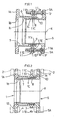
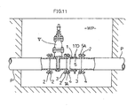
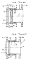
- FIGS 1-11 show a flexible pipe joint apparatus to be connected to an intermediate portion of a fluid transport pipe P such as a water pipe disposed inside a work bit WP.
- This flexible pipe joint apparatus includes a receiving tubular member 1 made of cast iron which integrally forms, at a base end thereof, a connecting flange 1A fixedly connectable to a connecting flange 2 of a fluid transport device such as a sluice valve V, the fluid transport pipe P or the like along a tube axial direction (tube axis) X via fastener means such as bolts 3 and nuts 4.
- the apparatus also includes an inserting tubular member 5 made of cast iron which is removably insertable into the receiver opening of the receiving tubular member 1 along the tube axial direction X.
- This inserting tubular member 5 too integrally forms, at a base end thereof, a connecting flange 5A fixedly connectable to the connecting flange 2 of the fluid transport device along the tube axial direction (tube axis) X via fastener means such as the bolts 3 and nuts 4.
- a radially projecting stopper portion 6 is provided at the leading end of an outer peripheral face of the inserting tubular member 5.
- a first annular groove 7 for defining, by contact, a predetermined relative slidable range (range of flexion) between the interconnected two tubular members 1, 5 along the tube axial direction X, and a second annular groove 9 within which an elastic seal 8 for sealing the gap formed between the inner peripheral face of the receiving tubular member 1 and the outer peripheral face of the inserting tubular member 5 is fitted.
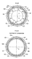
- the center angle ⁇ 1 is 40 degrees
- angles ⁇ 2 and ⁇ 6 are 50 degrees
- ⁇ 3 and ⁇ 5 are 75 degrees
- ⁇ 4 is 70 degrees, respectively.
- Figure 8 illustrates a condition when the plurality of projections 6A-6F of the inserting tubular member 5 and the plurality of detaching recesses 10A-10F are in registry or agreement with each other in the predetermined phase relationship.
- Figure 9 shows the further condition (predetermined retained position) suitable for shipment of the apparatus, in which the two tubular members 1, 5 have been rotated by 180 degrees relative to each other from the predetermined phase (connecting condition) to the predetermined retained condition, and under this condition, the tubular members 1, 5 are temporarily fixed against relative rotational and slidable displacements thereof by the temporary fixing means 11.
- Figure 10A shows a further condition in which the receiving tubular member 1 and the inserting tubular member 5 have been rotated by 5 degrees from the predetermined retained position described above.
- This condition or the rotational operation therefor is utilized when the flexible pipe joint apparatus shipped to the installment site is to be flange-connected with the fluid transport device by registering positions of bolt holes 12 between the connecting flange 2 of the receiving tubular member 1 and the connecting flange 1A and also positions of bolt holes 12 between the connecting flange 2 of the fluid transport pipe and the connecting flange 5A of the inserting tubular member 5.
- Figure 10B shows a further condition in which the receiving tubular member 1 and the inserting tubular member 5 have been rotated by 10 degrees from the predetermined retained position shown in Figure 9.
- Figures 10C-10F shows still further conditions in which the tubular members 1 and 5 have been rotated by 20 degrees from the predetermined retained position of Figure 9 by 15, 20, 25 and 30 degrees, respectively.
- all or some of the projections 6A-6F of the inserting tubular member 5 are placed in abutment along the tube axial direction X against the retaining portion 1C of the receiving tubular member 1, thereby to firmly and reliably prevent withdrawal displacement between the two tubular members 1, 5.
- the predetermined phase relationship where the projections 6A-6F of the inserting tubular member 5 together forming the stopper portion 6 and the detaching recesses 10A-10F of the receiving tubular member 1 together forming the retaining portion are in agreement is realized only one time during the total rotation (360 degrees).
- the two tubular members 1, 5 can be rotated by the maximum angle of rotation of 180 degrees from the predetermined phase condition (i.e., the connecting position) where the projections 6A-6F of the inserting tubular member 5 and the detaching recesses 10A-10F of the receiving tubular member 1 are in peripheral alignment with each other to the predetermined retained position.
- the projections 6A-6F and the detaching recesses 10A-10F are formed in symmetry with each other relative to the diametrical center line Y extending through the common axis X of the tubular members, it is easy for a user to visually find the predetermined phase relationship where the projections 6A-6F and the detaching recesses 10A-10F are in agreement. So that, the phase adjustment between the inserting tubular member 5 and the receiving tubular member 1 may be effected easily.
- the temporary fixing means 11 includes threaded holes 11A defined at two positions in the connecting flange 5A of the inserting tubular member 5, connecting portions 11D integrally formed at two peripheral positions in the outer peripheral face of the receiving tubular member 1 adjacent the receiver opening thereof, and two connecting bolts 11B interconnecting the threaded holes 11A and the connecting portions 11D.
- the threaded holes 11A are defined at two positions in the middle between the bolt holes 12 and opposing to each other across the tube axis X.
- the connecting portions 11D define engaging recesses 11C peripherally engageable with the respective connecting bolts 11B fixedly threaded into the screw holes 11A.
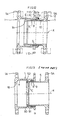
- an attaching portion 1a made of a synthetic film or in the form of a tubular rubber element, as an example of a 'covering means' having light-shielding, water-resistance and gas impermeable properties for covering the detaching recesses 10A-10F from the above.
- the inserting tubular member 5 includes, on its inner peripheral face and at portions corresponding to the projections 6A-6F formed on the outer peripheral face thereof, a plurality of projections 1b which project radially inward.
- This embodiment comprises another embodiment of the covering means for covering the detaching recesses 10A-10F.
- the covering means comprises a heat-shrinkable synthetic resin film 14 shrunk-fitted on and extending over and across a connecting portion between the attaching portion 1a on the outer peripheral face of the receiving tubular member 1 and the outer peripheral face of the inserting tubular member 5.
- the relative slidable range between the two tubular members 1, 5 along the tube axial direction X is limited by causing both the stopper portion 6 of the inserting tubular member 5 and the leading end face of the inserting tubular member 5 to selectively come into abutment in the tube axial direction X against the annular circular wall portion 1B on the base end side and the annular circular wall portion 1C on the receiving opening side of together defining the first annular groove 7 therebetween.
- the total six projections 6A-6F are formed on the inserting tubular member 5 and likewise the total six detaching recesses 10A-10F are formed in the receiving tubular member 1.
- the number, disposing pitch and specific dimensions, etc., of these projections and recesses are not particularly limited to the illustrated example, but may vary as suited.
- the specific construction of the temporary fixing means 11 provided in the flexible pipe joint apparatus of the invention is not limited to the one specifically described above, but may be modified in any way as long as such alternative construction can temporarily fix the two tubular members 1, 5 at least against relative rotational displacement thereof when these tubular members 1, 5 are interconnected in the predetermined phase condition and then rotated by a predetermined angle therefrom into the retained condition.
Landscapes
- Engineering & Computer Science (AREA)
- General Engineering & Computer Science (AREA)
- Mechanical Engineering (AREA)
- Joints Allowing Movement (AREA)
- Quick-Acting Or Multi-Walled Pipe Joints (AREA)
Claims (5)
- Dispositif flexible de raccord de tuyaux pour le transport de substances fluides comprenant un élément tubulaire de réception (1), un élément tubulaire d'insertion (5) apte à être inséré dans et à être raccordé avec l'élément tubulaire de réception (1) le long d'une direction d'un axe de tube, le dispositif comprenant :caractérisé en ce queune partie formant butée (6) formée dans une face périphérique extérieure de l'élément tubulaire d'insertion (5), la partie formant butée (6) faisant saillie dans le sens radial vers l'extérieur depuis la face périphérique extérieure ;une partie de retenue (1C) formée dans une face périphérique intérieure de l'élément tubulaire de réception (1), la partie de retenue (1C) venant en contact avec la partie formant butée (6) de l'élément tubulaire d'insertion (5) de manière à empêcher le déplacement par coulissement entre les deux éléments tubulaires (1, 5) au moins sur un côté de retrait dans une plage de coulissement relative prédéterminée des éléments tubulaires (1, 5) ;la partie formant butée (6) comprenant une pluralité de saillies (6A, 6B, 6C, 6D, 6E, 6F) formées à une pluralité de positions le long d'une périphérie de l'élément tubulaire d'insertion (5) ;la partie de retenue (1C) de l'élément tubulaire de réception (1) comprenant une pluralité de creux de détachement (10A, 10B, 10C, 10D, 10E, 10F), chaque dit creux permettant le passage de chacune des saillies (6A, 6B, 6C, 6D, 6E, 6F) dans le sens axial par rapport au creux de détachement uniquement lorsque l'élément tubulaire de réception (1) et l'élément tubulaire d'insertion (5) sont placés dans une relation de phase prédéterminée l'un avec l'autre ; etla pluralité de saillies (6A, 6B, 6C, 6D, 6E, 6F) et la pluralité de creux de détachement (10A, 10B, 10C, 10D, 10E, 10F) étant agencées en symétrie par rapport à une ligne centrale diamétrale s'étendant à travers l'axe commun (X) des éléments tubulaires (1, 5),
la pluralité de creux de détachement (10A, 10B, 10C, 10D, 10E, 10F) est répartie de manière périphérique de sorte que les paires adjacentes de manière périphérique des creux de détachement forment des angles centraux (1, 2, 3, 4, 5, 6) par rapport à l'axe de tube (X) lesquels angles sont différents l'un de l'autre. - Dispositif de raccord de tuyaux selon la revendication 1, caractérisé par des moyens de fixation temporaires (11) destinés à fixer temporairement les éléments tubulaires de réception et d'insertion (1, 5) pour qu'ils soient non rotatifs l'un par rapport à l'autre lorsque les éléments tubulaires (1, 5) sont dans une condition retenue qui est réalisée par le pivotement des éléments tubulaires de réception et d'insertion raccordés entre eux (1, 5) l'un par rapport à l'autre à partir de la relation de phase prédéterminée.
- Dispositif de raccord de tuyaux selon la revendication 1 ou 2, caractérisé par des moyens de recouvrement (14) qui s'étendent sur une partie raccordée entre la face périphérique extérieure de l'élément tubulaire de réception (1) et la face périphérique extérieure de l'élément tubulaire d'insertion (5) de manière à couvrir les creux de détachement (10A, 10B, 10C, 10D, 10E, 10F) ci-dessus.
- Dispositif de raccord de tuyaux selon la revendication 3, caractérisé par :des moyens de fixation temporaires (11) destinés à fixer temporairement les éléments tubulaires de réception et d'insertion (1, 5) pour qu'ils soient non rotatifs l'un par rapport à l'autre lorsque les éléments tubulaires (1, 5) sont dans une condition retenue qui est réalisée par le pivotement des éléments tubulaires de réception et d'insertion reliés entre eux (1, 5) l'un par rapport à l'autre à partir de ladite relation de phase prédéterminée, lesdits moyens de fixation temporaire (11) étant fixés de manière détachable à une bride de raccordement (5A) de l'élément tubulaire d'insertion (5) et également à une pluralité de parties de raccordement faisant saillie (11D) formées à une pluralité de positions périphériques dans la face périphérique extérieure de l'élément tubulaire de réception (1) adjacent à une ouverture de réception de celui-ci ; etune partie d'attachement (1a) pour les moyens de recouvrements (14) formés dans la face périphérique extérieure de l'élément tubulaire de réception (1) et entre une face d'extrémité de l'élément tubulaire de réception (1) adjacent à l'ouverture de réception de celui-ci et lesdites parties de raccordement (11D).
- Dispositif de raccord de tuyaux selon la revendication 1, caractérisé en ce que l'élément tubulaire d'insertion (5) comprend, sur une face périphérique intérieure et au niveau de parties correspondant aux saillies (6A, 6B, 6C, 6D, 6E, 6F) formées sur la face périphérique extérieure de celle-ci, une pluralité de saillies qui font saillie de façon radiale vers l'intérieur.
Applications Claiming Priority (2)
| Application Number | Priority Date | Filing Date | Title |
|---|---|---|---|
| JP2000080033A JP3621016B2 (ja) | 2000-03-22 | 2000-03-22 | 流体輸送用伸縮継手 |
| JP2000080033 | 2000-03-22 |
Publications (3)
| Publication Number | Publication Date |
|---|---|
| EP1136741A2 EP1136741A2 (fr) | 2001-09-26 |
| EP1136741A3 EP1136741A3 (fr) | 2002-05-15 |
| EP1136741B1 true EP1136741B1 (fr) | 2004-08-11 |
Family
ID=18597196
Family Applications (1)
| Application Number | Title | Priority Date | Filing Date |
|---|---|---|---|
| EP01106594A Expired - Lifetime EP1136741B1 (fr) | 2000-03-22 | 2001-03-15 | Dispositif flexible de raccord de tuyaux pour le transport de substances fluides |
Country Status (6)
| Country | Link |
|---|---|
| US (1) | US6659511B2 (fr) |
| EP (1) | EP1136741B1 (fr) |
| JP (1) | JP3621016B2 (fr) |
| CA (1) | CA2339298C (fr) |
| DE (1) | DE60104752T2 (fr) |
| HK (1) | HK1041040B (fr) |
Families Citing this family (22)
| Publication number | Priority date | Publication date | Assignee | Title |
|---|---|---|---|---|
| US7104572B1 (en) | 2004-10-27 | 2006-09-12 | Cascade Waterworks Manufacturing Co., Inc. | Tapping sleeve with mechanical joint connection |
| JP4190502B2 (ja) | 2005-01-19 | 2008-12-03 | 東京都 | 管接続構造 |
| US7784483B2 (en) * | 2005-01-21 | 2010-08-31 | Zurn Industries, Llc | Backflow preventer |
| JP4970140B2 (ja) * | 2007-05-25 | 2012-07-04 | コスモ工機株式会社 | 流体弁回動用冶具 |
| US8033576B2 (en) * | 2007-10-12 | 2011-10-11 | Flex-Hose Co. Inc. | Pipe guide for expansion joint |
| US20110101671A1 (en) * | 2009-04-22 | 2011-05-05 | Harry Frederick Dixon | Universal slip and expand fitting and method of using the same |
| SE534906C2 (sv) * | 2010-06-09 | 2012-02-14 | Itt Mfg Enterprises Inc | Suganslutning för förbindning av en sugledning till en torrt uppställd centrifugalpump |
| EP2607766B1 (fr) * | 2011-12-19 | 2016-04-27 | M & G Group Europe B.V. | Dispositif de serrage pour tuyaux de gaz combustible |
| WO2013177742A1 (fr) * | 2012-05-28 | 2013-12-05 | Gao Hongbing | Joint de dilatation marin comprenant un presse-étoupe |
| JP6032530B2 (ja) * | 2012-06-12 | 2016-11-30 | 株式会社栗本鐵工所 | ケーブル保護管の耐震継手構造 |
| WO2014091455A1 (fr) * | 2012-12-13 | 2014-06-19 | Guala Closures S.P.A. | Système permettant de raccorder deux éléments tubulaires et réceptacle pour liquides doté dudit système de raccordement |
| US9945506B2 (en) | 2013-08-14 | 2018-04-17 | GE—Hitachi Nuclear Energy Americas LLC | Seismic slip joint, seismic-mitigating piping system, and method of mitigating seismic effects on a piping system |
| US9267615B1 (en) * | 2013-10-30 | 2016-02-23 | Cortec, L.L.C. | Method and apparatus for removing, repairing, refurbishing, replacing, and/or installing valve between two fixed spool pieces |
| EP3094910A4 (fr) * | 2013-12-19 | 2018-01-17 | Mile Dudurovic | Jonction de démontage |
| US10203043B2 (en) | 2015-11-16 | 2019-02-12 | Ge-Hitachi Nuclear Energy Americas Llc | Systems and methods for high-reliability valve opening |
| US10533310B2 (en) * | 2016-07-28 | 2020-01-14 | Masco Canada Limited | Flushometer valve to outlet tube coupling |
| JP6845524B2 (ja) * | 2016-08-10 | 2021-03-17 | 明和工業株式会社 | 管長調整継手 |
| US20190203859A1 (en) * | 2017-12-28 | 2019-07-04 | Nathaniel Shackelford | Pipe splicing assembly |
| GB2571070B (en) * | 2018-02-07 | 2022-09-14 | David George Hanney Richard | An apparatus for joining and extending pipework or pipes |
| KR102421409B1 (ko) * | 2020-07-15 | 2022-07-18 | 주식회사 에스제이엠 | 고정 링을 포함하는 외압형 벨로우즈 익스펜션 조인트 |
| CN113404954B (zh) * | 2021-06-21 | 2022-11-18 | 哈尔滨工程大学 | 水下螺栓预紧可伸缩式连接器 |
| CN118030979A (zh) * | 2024-03-05 | 2024-05-14 | 玫德集团有限公司 | 一种防压缩位移pvc-pe管道转换接头装配方法 |
Family Cites Families (10)
| Publication number | Priority date | Publication date | Assignee | Title |
|---|---|---|---|---|
| US2922667A (en) * | 1958-10-13 | 1960-01-26 | Jr Claude O Lanciano | Telescopic hose unit and coupling therefor |
| US3131642A (en) * | 1962-11-30 | 1964-05-05 | Wilfley & Sons Inc A | Standpipe connection for centrifugal pumps |
| US4280723A (en) * | 1978-07-26 | 1981-07-28 | Moldestad Jon P | Safety device for hose connections |
| US4610471A (en) * | 1985-10-29 | 1986-09-09 | Coupling Systems, Inc. | Flange adapters |
| US5116085A (en) * | 1990-06-11 | 1992-05-26 | Bishamon, Inc. | Sealed expansion joint |
| US5421621A (en) * | 1993-06-14 | 1995-06-06 | Adsco Manufacturing Company | Packing manifold for slip-type expansion joints |
| JPH09264473A (ja) * | 1996-03-29 | 1997-10-07 | Osaka Gas Co Ltd | 管継手構造 |
| JPH09292074A (ja) * | 1996-04-25 | 1997-11-11 | Hazu Kogyo Kk | 伸縮管継ぎ手 |
| AUPO120696A0 (en) * | 1996-07-24 | 1996-08-15 | Jott Australia Pty. Ltd. | Improvements in closure arrangements for containers |
| JPH11264491A (ja) * | 1998-03-17 | 1999-09-28 | Osaka Gas Co Ltd | 管継手構造 |
-
2000
- 2000-03-22 JP JP2000080033A patent/JP3621016B2/ja not_active Expired - Lifetime
-
2001
- 2001-03-02 CA CA002339298A patent/CA2339298C/fr not_active Expired - Lifetime
- 2001-03-15 DE DE60104752T patent/DE60104752T2/de not_active Expired - Lifetime
- 2001-03-15 EP EP01106594A patent/EP1136741B1/fr not_active Expired - Lifetime
- 2001-03-16 US US09/810,594 patent/US6659511B2/en not_active Expired - Lifetime
-
2002
- 2002-03-14 HK HK02101987.1A patent/HK1041040B/en not_active IP Right Cessation
Also Published As
| Publication number | Publication date |
|---|---|
| HK1041040B (en) | 2005-03-11 |
| CA2339298C (fr) | 2008-12-16 |
| DE60104752T2 (de) | 2005-01-20 |
| US20010024037A1 (en) | 2001-09-27 |
| JP3621016B2 (ja) | 2005-02-16 |
| DE60104752D1 (de) | 2004-09-16 |
| HK1041040A1 (en) | 2002-06-28 |
| US6659511B2 (en) | 2003-12-09 |
| EP1136741A3 (fr) | 2002-05-15 |
| EP1136741A2 (fr) | 2001-09-26 |
| JP2001263565A (ja) | 2001-09-26 |
| CA2339298A1 (fr) | 2001-09-22 |
Similar Documents
| Publication | Publication Date | Title |
|---|---|---|
| EP1136741A2 (fr) | Dispositif flexible de raccord de tuyaux pour le transport de substances fluides | |
| US5603530A (en) | Grab rings | |
| US4783100A (en) | Swivel joint | |
| JP7732056B2 (ja) | 管接続部の離脱防止構造 | |
| US20060171776A1 (en) | Quick torque coupling | |
| JP5060181B2 (ja) | 管継手部の離脱防止構造 | |
| GB2038435A (en) | Slipping off preventing pipe joint | |
| US8632104B2 (en) | Pipe joint construction | |
| CA2459637C (fr) | Raccord de tuyauterie | |
| JP2007255685A (ja) | 管継手 | |
| US7201404B1 (en) | Union nut with lock member | |
| JP4542364B2 (ja) | 管接続構造及び挿口管部への管内作業機の取付け方法 | |
| JP2024009299A (ja) | 管継手離脱防止構造 | |
| JPH0972470A (ja) | 流体管連結用伸縮流体管 | |
| KR100393349B1 (ko) | 삽입구에돌출부를보유하는관과그돌출부의형성방법 | |
| JP2008169868A (ja) | 管継手部の離脱防止構造と挿口管部の係止部大径改造方法及び挿口管部用係止部大径改造具 | |
| JP3531147B2 (ja) | ユニオンナット継手用管離脱防止装置及びプラスチックリング | |
| JP3257900B2 (ja) | 離脱防止管継手 | |
| JPH09264473A (ja) | 管継手構造 | |
| JP2003166682A (ja) | 伸縮管継手 | |
| EP1820976B1 (fr) | Dispositif d'assemblage pour corps structurel | |
| JP2001241581A (ja) | 管継手 | |
| JP2004138234A (ja) | 管継手方法 | |
| JP2000193163A (ja) | 管体の伸縮自在継手構造 | |
| JP4408064B2 (ja) | 伸縮継手部の離脱防止装置 |
Legal Events
| Date | Code | Title | Description |
|---|---|---|---|
| PUAI | Public reference made under article 153(3) epc to a published international application that has entered the european phase |
Free format text: ORIGINAL CODE: 0009012 |
|
| AK | Designated contracting states |
Kind code of ref document: A2 Designated state(s): AT BE CH CY DE DK ES FI FR GB GR IE IT LI LU MC NL PT SE TR |
|
| AX | Request for extension of the european patent |
Free format text: AL;LT;LV;MK;RO;SI |
|
| PUAL | Search report despatched |
Free format text: ORIGINAL CODE: 0009013 |
|
| AK | Designated contracting states |
Kind code of ref document: A3 Designated state(s): AT BE CH CY DE DK ES FI FR GB GR IE IT LI LU MC NL PT SE TR |
|
| AX | Request for extension of the european patent |
Free format text: AL;LT;LV;MK;RO;SI |
|
| 17P | Request for examination filed |
Effective date: 20020703 |
|
| AKX | Designation fees paid |
Designated state(s): DE FR GB IT |
|
| 17Q | First examination report despatched |
Effective date: 20030414 |
|
| GRAP | Despatch of communication of intention to grant a patent |
Free format text: ORIGINAL CODE: EPIDOSNIGR1 |
|
| GRAS | Grant fee paid |
Free format text: ORIGINAL CODE: EPIDOSNIGR3 |
|
| GRAA | (expected) grant |
Free format text: ORIGINAL CODE: 0009210 |
|
| AK | Designated contracting states |
Kind code of ref document: B1 Designated state(s): DE FR GB IT |
|
| REG | Reference to a national code |
Ref country code: GB Ref legal event code: FG4D |
|
| REG | Reference to a national code |
Ref country code: IE Ref legal event code: FG4D |
|
| REF | Corresponds to: |
Ref document number: 60104752 Country of ref document: DE Date of ref document: 20040916 Kind code of ref document: P |
|
| REG | Reference to a national code |
Ref country code: HK Ref legal event code: GR Ref document number: 1041040 Country of ref document: HK |
|
| ET | Fr: translation filed | ||
| PLBE | No opposition filed within time limit |
Free format text: ORIGINAL CODE: 0009261 |
|
| STAA | Information on the status of an ep patent application or granted ep patent |
Free format text: STATUS: NO OPPOSITION FILED WITHIN TIME LIMIT |
|
| 26N | No opposition filed |
Effective date: 20050512 |
|
| REG | Reference to a national code |
Ref country code: FR Ref legal event code: PLFP Year of fee payment: 15 |
|
| REG | Reference to a national code |
Ref country code: FR Ref legal event code: PLFP Year of fee payment: 16 |
|
| REG | Reference to a national code |
Ref country code: FR Ref legal event code: PLFP Year of fee payment: 17 |
|
| REG | Reference to a national code |
Ref country code: FR Ref legal event code: PLFP Year of fee payment: 18 |
|
| PGFP | Annual fee paid to national office [announced via postgrant information from national office to epo] |
Ref country code: DE Payment date: 20200312 Year of fee payment: 20 Ref country code: IT Payment date: 20200325 Year of fee payment: 20 Ref country code: GB Payment date: 20200325 Year of fee payment: 20 |
|
| PGFP | Annual fee paid to national office [announced via postgrant information from national office to epo] |
Ref country code: FR Payment date: 20200325 Year of fee payment: 20 |
|
| REG | Reference to a national code |
Ref country code: DE Ref legal event code: R071 Ref document number: 60104752 Country of ref document: DE |
|
| REG | Reference to a national code |
Ref country code: GB Ref legal event code: PE20 Expiry date: 20210314 |
|
| PG25 | Lapsed in a contracting state [announced via postgrant information from national office to epo] |
Ref country code: GB Free format text: LAPSE BECAUSE OF EXPIRATION OF PROTECTION Effective date: 20210314 |