EP1138376A2 - Handhabung von Teilchen - Google Patents
Handhabung von Teilchen Download PDFInfo
- Publication number
- EP1138376A2 EP1138376A2 EP01303049A EP01303049A EP1138376A2 EP 1138376 A2 EP1138376 A2 EP 1138376A2 EP 01303049 A EP01303049 A EP 01303049A EP 01303049 A EP01303049 A EP 01303049A EP 1138376 A2 EP1138376 A2 EP 1138376A2
- Authority
- EP
- European Patent Office
- Prior art keywords
- hopper
- chamber
- particulate
- outlet port
- kinetic energy
- Prior art date
- Legal status (The legal status is an assumption and is not a legal conclusion. Google has not performed a legal analysis and makes no representation as to the accuracy of the status listed.)
- Withdrawn
Links
Images


Classifications
-
- B—PERFORMING OPERATIONS; TRANSPORTING
- B01—PHYSICAL OR CHEMICAL PROCESSES OR APPARATUS IN GENERAL
- B01J—CHEMICAL OR PHYSICAL PROCESSES, e.g. CATALYSIS OR COLLOID CHEMISTRY; THEIR RELEVANT APPARATUS
- B01J8/00—Chemical or physical processes in general, conducted in the presence of fluids and solid particles; Apparatus for such processes
- B01J8/02—Chemical or physical processes in general, conducted in the presence of fluids and solid particles; Apparatus for such processes with stationary particles, e.g. in fixed beds
- B01J8/0242—Chemical or physical processes in general, conducted in the presence of fluids and solid particles; Apparatus for such processes with stationary particles, e.g. in fixed beds the fluid flow within the bed being predominantly vertical
- B01J8/025—Chemical or physical processes in general, conducted in the presence of fluids and solid particles; Apparatus for such processes with stationary particles, e.g. in fixed beds the fluid flow within the bed being predominantly vertical in a cylindrical shaped bed
-
- B—PERFORMING OPERATIONS; TRANSPORTING
- B01—PHYSICAL OR CHEMICAL PROCESSES OR APPARATUS IN GENERAL
- B01J—CHEMICAL OR PHYSICAL PROCESSES, e.g. CATALYSIS OR COLLOID CHEMISTRY; THEIR RELEVANT APPARATUS
- B01J8/00—Chemical or physical processes in general, conducted in the presence of fluids and solid particles; Apparatus for such processes
- B01J8/0015—Feeding of the particles in the reactor; Evacuation of the particles out of the reactor
- B01J8/003—Feeding of the particles in the reactor; Evacuation of the particles out of the reactor in a downward flow
-
- B—PERFORMING OPERATIONS; TRANSPORTING
- B01—PHYSICAL OR CHEMICAL PROCESSES OR APPARATUS IN GENERAL
- B01J—CHEMICAL OR PHYSICAL PROCESSES, e.g. CATALYSIS OR COLLOID CHEMISTRY; THEIR RELEVANT APPARATUS
- B01J2208/00—Processes carried out in the presence of solid particles; Reactors therefor
- B01J2208/00008—Controlling the process
- B01J2208/00654—Controlling the process by measures relating to the particulate material
- B01J2208/0069—Attrition
Definitions
- This invention relates to improvements in or relating to particulate handling apparatus, and especially but not exclusively to apparatus suitable for handling the of particulates which have, during transportation to the apparatus, been imparted with a high kinetic energy.
- pellet will be used to describe particulates in general.
- pellets can be conveyed pneumatically using a gas to entrain the solids.
- pneumatic conveyance systems are used to transfer pellets between containers, for example from chemical reactors into drums or vice versa.
- the transfer of pellets may be to load a reactor vessel, or unload a reactor vessel to allow treatment of the catalyst or rebedding of the catalyst.
- a primary objective for a pneumatic conveying system is to convey the pellets at the highest possible rate.
- the entrained pellet gas mixture is forced through piping, conduits or ducting at the highest possible velocity.
- a problem, however, with such an approach is that the higher the velocity of transportation of the pellets, the greater the kinetic energy each pellet acquires.
- a particulate handling system which is suitable for the transfer of kinetic energy from particles of transported particulate material and which lessens the damage suffered by said particulate material by the removal of that kinetic energy.
- a particulate material handling apparatus which includes separation means for separating conveyed particulate from a conveying gas, at least one energy reducing means for reducing the kinetic energy of said particulate, and a loading hopper, in which said means are so arranged relative to each other that when in use particulate passes through the separation means, the kinetic energy reduction means and into the loading hopper.
- the separation means is comprised of a first chamber having an inlet port, and first and second outlet ports, in which particulate may exit the first chamber via the first outlet port, and the conveying gas may be exhausted via the second outlet port.
- the first chamber is configured so that combined conveying gas and particulate enters through the inlet port, and the inertia of the particulate carries the particulate towards the first outlet port.
- separation means for separating conveyed particulate material from a conveying gas, which means includes a first chamber having an inlet port arranged to receive the conveyed gas and particulate material and first and second outlet ports, in which particulate may exit the first chamber via the first outlet port and the conveying gas is exhausted via the second outlet port.
- the first chamber is preferably of greater cross sectional volume than the inlet port and, thus after entry via the inlet port the conveying gas slows down and drops the particulate which continues, because of inertia, to travel toward and out of the outlet port.
- the conveying gas is induced to exhaust from the first chamber via the second outlet port by way of a means causing the second outlet port to be at reduced pressure relative to the first chamber. This causes the conveying gas to exit the first chamber.
- a preferred kinetic energy reducing means may be comprised of a second chamber having an inlet and an outlet port between which is at least one flexible baffle.
- Each baffle is so located in the second chamber that pellets impact upon the baffle when passing between the inlet port and outlet port. It is most preferred that the baffles are made from a flexible material that is so configured that each baffle is capable of absorbing energy when impacted by a pellet, but which does not absorb all of the kinetic energy of the pellet.
- Such materials may be of any flexible material including soft plastics, or most preferably, of natural or artificial rubber.
- Kinetic energy reduction means for reducing kinetic energy of particulate material which means includes a chamber having an inlet port area and an outlet port having arranged therebetween at least one flexible baffle arranged such that the material impacts upon the baffle when passing from the inlet port to the outlet port.
- each baffle is comprised of a plurality of strips of sheet rubber. One end of each strip of sheet rubber being attached to a wall of the second chamber and the other end of each strip of sheet rubber being free.
- the thickness of the sheet rubber employed and the number of strips that comprise the baffle are dependent upon the expected kinetic energy of the particulate material. The desired thickness and number of strips may either be determined empirically or theoretically.
- the chamber is adapted to allow the rapid attachment and detachment of baffles to one wall of said second chamber; this allows empirical determination of the optimal number of strips and optimal thickness of each strip.
- the means for attachment may include standard fixing means or slots through the wall of the second chamber.
- the second chamber may be formed from a portion of pipe or ducting with the strips being attached either to an internal wall of said pipe or ducting or being inserted into said pipe or ducting via slots through said wall.
- the wall may be provided with a large number of slots which can either be used to anchor a strip of kinetic energy absorbing material or may be blanked off when not in use.
- kinetic energy reduction means for reducing kinetic energy of particulate material which means includes an inlet pipe or duct support means arranged to support a pipe or duct having a flexible portion.
- a second kinetic energy reduction means includes an inlet pipe or duct support means and a hinged flexible pipe or duct section located between the separation means and the loading hopper.
- the inlet pipe or duct support means supports the inlet pipe or duct at or substantially adjacent to the separation means, and is provided with means to allow the disposition of the major axis of the pipe or duct between the separation means and the hinged flexible pipe or duct section to be adjusted with respect to the horizontal. Adjustment of the disposition of that pipe or duct with respect to the horizontal may cause the particulate to either have to flow uphill, horizontally, or downhill to the hinged flexible pipe section.
- the nature and degree of the slope that the pellets have to flow along are features that affect the amount of kinetic energy the particulate loses whilst travelling between the separation means and the flexible pipe or duct.
- the pipe or duct between the separation means and the hinged flexible pipe section may be of a standard material used in the construction of catalyst handling equipment such as steel, or may be internally coated with an energy absorbing material such as a soft plastics or a natural or artificial rubber. Furthermore, the internal surface of said pipe may be substantially smooth or may be contoured to alter the energy absorbing characteristics of said surface.
- the pipe or duct may be so constructed that the distance between the separation means and the hinged flexible portion may be varied. This again affects the amount of kinetic energy absorbed from the particulate flowing through the pipe or duct.
- the hopper of the present invention is designed and configured to try to minimise the force of impacts experienced by particulate material entering the hopper and thus impacting on its walls. This is at least partially achieved by causing the entry angle of the particulate material into the hopper to be such that when the particulate material first impacts a wall of the hopper it does so at an acute angle to the surface of the hopper.
- the particulate material is thus not subjected to a sudden deceleration, rather it is subject to one or more small decelerations.
- the force of the impact may be lessened by making the inner surface of the hopper from an energy absorbing material such as a soft plastic, or an artificial or natural rubber.
- the surface may be smooth or may be contoured to alter the energy absorbance characteristics of the surface.
- the loading hopper is substantially circular in horizontal cross section (when in use) and the pellets introduced into the hopper substantially tangentially (at the point of introduction) to the inside surface of the hopper.
- the hopper has an internal shape that is substantially conical with the cone narrowing towards the bottom of the hopper when in use.
- the hopper is provided with an outlet port which is substantially at the apex of the cone.
- the hopper is further provided with a cylindrical section, one end of which mouths onto and engages with the widest portion of the conical section and the other end of which is closed.
- the closed end may be provided with a vision panel.
- the hopper is further provided with a mounting flange adapted to engage with a manway on a reactor vessel or a drum for conveying the particulate material.
- the pellets may bear the appearance of a cyclonic air flow type separator
- the pellets enter the hopper with some, but not very much, gas and, because of the kinetic energy reduction means that the pellets have already passed through, they enter relatively slowly. As such, no cyclonic type separation occurs. Indeed, in a particularly preferred embodiment of the present invention there is no gas flowing through the hopper at all.
- the present invention is also concerned with a method of transferring kinetic energy from particulate material.
- the method typically includes permitting particulate material to pass through the apparatus according to the first aspect of the present invention.
- the first chamber is configured so that combined conveying gas and particulate enters through the inlet port, and the inertia of the particulate carries the particulate towards the first outlet port.
- the apparatus of the illustrated embodiment of the present invention is intended for use in connection with particulate in the form of pellets of diameter between 3 and 16 mm that enter the apparatus illustrated at high velocities, and as such with high kinetic energies.
- the apparatus comprises a separation chamber means (12) comprising a tube (14) within which is located a smaller dimensioned tube (16).
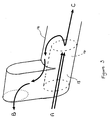
- Tube (16) forms an inlet (18) to the separation chamber through which pellets (not shown) entrained in a high velocity stream of pneumatic carrier gas (as shown by arrow A in Figures 2, 3 and 4) may be delivered into the separation chamber.
- An end portion of tube (14) distal from tube (16) provides a first outlet (20) through which pellets may exit tube (14).
- a first kinetic energy reduction means is formed by baffle means (22) and is located in chamber (24) situated between inlet (18) and first outlet (20) of the tube in such a way as to be impacted by pellets flowing along the tube.
- the baffle means (22) comprises a number of rubber strips (26) suspended from the top of the chamber (24) of the tube. The rubber strips are arranged in three rows placed across the direction of flow of the pellets and a pellet would impact the rows of strips one after another.
- the outlet (20) mouths through the surface of a cylindrical portion (28) of a hopper (30).
- the orientation of tube (14) relative to the hopper (30) is such that in use pellets exiting from outlet (20) do so tangentially to the inner surface of the cylindrical portion (28) of the hopper (at the position of mouthing of outlet (20)).
- the upper surface of hopper (30) is closed and provided with a glass inspection window (32).
- a lower, conical portion (34) of the hopper (30) is provided with an exit orifice (38), and on the outer surface of the hopper, a flange (36).
- Flange (36) is fitted with an airtight seal and is adapted to be flanged to a top manway flange of a reactor vessel. Exit orifice (38) of the hopper allows pellets entering into the hopper to exit the hopper and be delivered to their final desired position in the reactor vessel via known means such as a loading sock.
- the tube (16) is mounted within and secured to a lower internal surface of the tube (14). Adjacent tube (14) and located above it, an outlet tube (42) is secured to the tube (14) with the major axis of the tubes being parallel to each other. Outlet tube (42) mouths into the separation means via an outlet (44). Outlet tube (42) is in communication with means (not shown) that causes the pneumatic carrier gas to be drawn through tube (42) so exhausting said gas from the separation means. The gas flows in the direction of arrow B ( Figures 2 and 3). As may be seen from Figures 2 and 3 and the arrow B, the outlet (44) is located adjacent the inlet (18) to the separation means so as to cause the exhaust pneumatic carrier gas to be vented in a direction opposite to that which it enters the separation means. This has the effect of minimising the amount of particulate material exiting the separation means via outlet (44).
- the illustrated apparatus is also provided with a second kinetic energy reduction means.
- tubes (14) and (42) are suspended via a threaded rod (46) from a support frame (48).
- An internally threaded handwheel (50) is mounted on the threaded rod (46) and serves to enable adjustment of the disposition of the major axis of the tube (14) with respect to the horizontal by moving the tubes (14) and (42) up and down relative to the support frame (48).
- a hinged flexible pipe section (52) is provided intermediate the separation means (12) and the first outlet (20). This arrangement enables the inclination of the tube (14) to the horizontal to be adjusted. Examples of possible inclinations are shown in Figure 4.
- the angle of incline of the tube (14) may either provide the tube (14) with a downhill slope (downhill being defined by the direction of travel of the pellets indicated by arrow A) as shown in Figure 4(a), a flat surface as shown in Figure 4(b), and an uphill slope as shown in Figure 4(c).
- the kinetic energy lost by pellets passing along the tube (14) increases from Figures 4(a) to 4(b) to 4(c).
- the hopper (30) is sealingly secured to the upper manway of a reactor vessel (40)via flange (36).
- the reactor vessel (40) is completely sealed off from any process gas by blinding or turning off any inlet or outlet process valves to the reactor.
- both the reactor and the catalyst handling system of the present invention are sealed off from external atmosphere, thus allowing both the apparatus and the reactor to be placed under negative pressure.
- the need for an airlock at the base of the hopper (28) is eliminated. This allows continuous loading of the catalyst bed in the reactor and reduces the build-up of catalyst pellets in the hopper (28).
- a stream of pellets of diameter between 3 and 16 mm and of higher or lower densities as desired is delivered entrained in a high velocity stream of pneumatic carrier gas through ducting and via the smaller diameter tube (16) into the separation means (12).
- the pneumatic carrier gas As the pneumatic carrier gas enters the larger volume of tube (14) it drops the pellets suspended in it, and is induced to flow out of the separation means via outlet (44) by means such as a vacuum pump in communication with outlet tube (42).
- the ensuing reduced volume of carrier gas and particles enters the chamber (24) where, again, the carrier gas may slow down and drop particulate matter.
- the pellets impact the baffle means. The impact of the pellets on the baffle means will cause the baffle means to deform or flex and absorb energy from the pellets.
- the pellets flow in the direction of arrow C into the hopper (28).
- the remaining kinetic energy possessed by the pellets when they enter hopper (28) causes the pellets to roll around the outside surface of hopper (28). This rolling round the outside surface of hopper (28) will cause the transfer of kinetic energy from the pellets to the hopper and allow the pellets to move, under the influence of gravity, toward mouth (38) of the hopper (28).
- the kinetic energy absorption means that the pellets have passed through are appropriate for the particular pellets, the kinetic energy possessed by the pellets when they pass into the hopper should be insufficient to cause an impact in the hopper that will damage the pellets.
- Adjustment of the kinetic energy being absorbed by the apparatus whilst a particulate material is flowing through the apparatus may be achieved by adjustment of the disposition of the major axis of tube (14) relative to the horizontal.
- An operator may view the pellets entering the hopper (28) via the viewing window (32) and cause fine adjustment to the kinetic energy of the pellets as they enter the hopper. If the amount of strips in the baffle means (22) remains constant, experience will allow an operator to calibrate the disposition of the major axis of the tube (14) relative to horizontal by the mass of the pellets being conveyed through the apparatus and/or the size of the pellets. This may be done by attaching a plumb line (or the like) and a graduated scale to the tube (14).
Landscapes
- Chemical & Material Sciences (AREA)
- Organic Chemistry (AREA)
- Chemical Kinetics & Catalysis (AREA)
- Physics & Mathematics (AREA)
- Fluid Mechanics (AREA)
- Control And Other Processes For Unpacking Of Materials (AREA)
- Air Transport Of Granular Materials (AREA)
- Filling Or Emptying Of Bunkers, Hoppers, And Tanks (AREA)
Applications Claiming Priority (2)
| Application Number | Priority Date | Filing Date | Title |
|---|---|---|---|
| GB0007846 | 2000-03-31 | ||
| GB0007846A GB0007846D0 (en) | 2000-03-31 | 2000-03-31 | Particulate handling apparatus |
Publications (2)
| Publication Number | Publication Date |
|---|---|
| EP1138376A2 true EP1138376A2 (de) | 2001-10-04 |
| EP1138376A3 EP1138376A3 (de) | 2003-05-14 |
Family
ID=9888854
Family Applications (1)
| Application Number | Title | Priority Date | Filing Date |
|---|---|---|---|
| EP01303049A Withdrawn EP1138376A3 (de) | 2000-03-31 | 2001-03-30 | Handhabung von Teilchen |
Country Status (2)
| Country | Link |
|---|---|
| EP (1) | EP1138376A3 (de) |
| GB (1) | GB0007846D0 (de) |
Cited By (3)
| Publication number | Priority date | Publication date | Assignee | Title |
|---|---|---|---|---|
| EP1374985A4 (de) * | 2001-03-26 | 2006-02-22 | Boreskova Inst Kataliza Sibir | Verfahren und vorrichtung zum eintragen von teilchen in ein rohr eines rohrreaktors |
| WO2008003921A1 (en) * | 2006-06-07 | 2008-01-10 | Catalyst Handling Research And Engineering Limited | Improved particulate handling apparatus and method |
| WO2012059235A1 (de) * | 2010-11-05 | 2012-05-10 | Mtu Friedrichshafen Gmbh | Vorrichtung und verfahren zur herstellung einer mit katalysatorpellets befüllten reformiereinheit |
Family Cites Families (7)
| Publication number | Priority date | Publication date | Assignee | Title |
|---|---|---|---|---|
| US2310377A (en) * | 1940-10-31 | 1943-02-09 | Standard Oil Co | System for handling abrasive powder |
| FR1363939A (fr) * | 1962-03-22 | 1964-06-19 | Smidth & Co As F L | Procédé et appareil pour l'échange de chaleur entre des particules solides et des gaz |
| US4606814A (en) * | 1984-11-01 | 1986-08-19 | Mobil Oil Corporation | FCC product withdrawal and separation |
| EP0305152B1 (de) * | 1987-08-25 | 1992-08-12 | Technivac Limited | Pneumatisches Fördersystem |
| US4904281A (en) * | 1988-07-15 | 1990-02-27 | Engelhard Corporation | Method and apparatus for separation of solids from a gaseous stream |
| US5215553A (en) * | 1992-09-08 | 1993-06-01 | Blowhard Pneumatic Services Inc. | Apparatus for separating particles from a gaseous medium |
| GB9307780D0 (en) * | 1993-04-15 | 1993-06-02 | Technivac Ltd | Method of charging a vessel with particulate material |
-
2000
- 2000-03-31 GB GB0007846A patent/GB0007846D0/en not_active Ceased
-
2001
- 2001-03-30 EP EP01303049A patent/EP1138376A3/de not_active Withdrawn
Cited By (6)
| Publication number | Priority date | Publication date | Assignee | Title |
|---|---|---|---|---|
| EP1374985A4 (de) * | 2001-03-26 | 2006-02-22 | Boreskova Inst Kataliza Sibir | Verfahren und vorrichtung zum eintragen von teilchen in ein rohr eines rohrreaktors |
| WO2008003921A1 (en) * | 2006-06-07 | 2008-01-10 | Catalyst Handling Research And Engineering Limited | Improved particulate handling apparatus and method |
| GB2438929B (en) * | 2006-06-07 | 2011-10-26 | Catalyst Handling Res & Engineering Ltd | Improved particulate handling apparatus and method |
| AU2007270989B2 (en) * | 2006-06-07 | 2012-04-12 | Catalyst Handling Research And Engineering Limited | Improved particulate handling apparatus and method |
| US8876439B2 (en) | 2006-06-07 | 2014-11-04 | Patrick Gerrard Sheehan | Particulate handling apparatus and method |
| WO2012059235A1 (de) * | 2010-11-05 | 2012-05-10 | Mtu Friedrichshafen Gmbh | Vorrichtung und verfahren zur herstellung einer mit katalysatorpellets befüllten reformiereinheit |
Also Published As
| Publication number | Publication date |
|---|---|
| GB0007846D0 (en) | 2000-05-17 |
| EP1138376A3 (de) | 2003-05-14 |
Similar Documents
| Publication | Publication Date | Title |
|---|---|---|
| US8876439B2 (en) | Particulate handling apparatus and method | |
| US4019641A (en) | Elevating and conveying system for unloading vessels or the like | |
| CN100406142C (zh) | 分离方法和装置 | |
| JPH0228404A (ja) | 粉粒体の積み込みシュート | |
| CA1110210A (en) | Method and apparatus for low-dust discharge of particulate material through a nozzle | |
| KR100294982B1 (ko) | 깨끗한입자분급기 | |
| EP1138376A2 (de) | Handhabung von Teilchen | |
| US3867116A (en) | Separator | |
| US6471737B2 (en) | Underbooth powder paint collector | |
| US4699710A (en) | Separator for particulates | |
| JPH05147734A (ja) | ダスト除去装置 | |
| CN220142964U (zh) | 一种气体吸附系统、脱附系统和吸附脱附系统 | |
| JPH1133386A (ja) | 回分造粒・コーティング方法及びその装置 | |
| US6176276B1 (en) | Granular material feeding device | |
| RU2021188C1 (ru) | Устройство для перегрузки сыпучих материалов из мягких контейнеров | |
| GB2287016A (en) | Charging a container with particulate solids material | |
| US4995499A (en) | Method and apparatus for reducing the velocity of particulate matter | |
| EP0254372A1 (de) | Verfahren und Vorrichtung, um feste, poröse Teilchen zu trocknen | |
| EP0091438A1 (de) | Verfahren zum fördern von pulverförmigem material, sowie vorrichtung zur ausführung dieses verfahrens. | |
| RU47860U1 (ru) | Система пневматического транспортирования сыпучего материала и аэроконвейер для использования в указанной системе | |
| JPS5850135B2 (ja) | 流動層装置 | |
| RU2286939C2 (ru) | Система пневматического транспортирования сыпучего материала и аэроконвейер для использования в указанной системе | |
| JPS5948672B2 (ja) | 篩分け装置 | |
| JPH02147519A (ja) | 高密度空気輸送された錠剤の捕集装置 | |
| JPS5823148B2 (ja) | 風力選別機 |
Legal Events
| Date | Code | Title | Description |
|---|---|---|---|
| PUAI | Public reference made under article 153(3) epc to a published international application that has entered the european phase |
Free format text: ORIGINAL CODE: 0009012 |
|
| AK | Designated contracting states |
Kind code of ref document: A2 Designated state(s): AT BE CH CY DE DK ES FI FR GB GR IE IT LI LU MC NL PT SE TR |
|
| AX | Request for extension of the european patent |
Free format text: AL;LT;LV;MK;RO;SI |
|
| PUAL | Search report despatched |
Free format text: ORIGINAL CODE: 0009013 |
|
| AK | Designated contracting states |
Designated state(s): AT BE CH CY DE DK ES FI FR GB GR IE IT LI LU MC NL PT SE TR |
|
| AX | Request for extension of the european patent |
Extension state: AL LT LV MK RO SI |
|
| 17P | Request for examination filed |
Effective date: 20031113 |
|
| AKX | Designation fees paid |
Designated state(s): AT BE CH CY DE DK ES FI FR GB GR IE IT LI LU MC NL PT SE TR |
|
| STAA | Information on the status of an ep patent application or granted ep patent |
Free format text: STATUS: THE APPLICATION IS DEEMED TO BE WITHDRAWN |
|
| 18D | Application deemed to be withdrawn |
Effective date: 20101001 |