EP1138466A1 - Formwerkzeug mit Druckmittel, für automatische Muffenformmaschinen, zum bleibenden Formen von Muffen mit Dichtung an Kunststoff-Rohrenden - Google Patents
Formwerkzeug mit Druckmittel, für automatische Muffenformmaschinen, zum bleibenden Formen von Muffen mit Dichtung an Kunststoff-Rohrenden Download PDFInfo
- Publication number
- EP1138466A1 EP1138466A1 EP00830246A EP00830246A EP1138466A1 EP 1138466 A1 EP1138466 A1 EP 1138466A1 EP 00830246 A EP00830246 A EP 00830246A EP 00830246 A EP00830246 A EP 00830246A EP 1138466 A1 EP1138466 A1 EP 1138466A1
- Authority
- EP
- European Patent Office
- Prior art keywords
- drift
- pipe
- flange
- moulds
- operating head
- Prior art date
- Legal status (The legal status is an assumption and is not a legal conclusion. Google has not performed a legal analysis and makes no representation as to the accuracy of the status listed.)
- Granted
Links
Images

Classifications
-
- B—PERFORMING OPERATIONS; TRANSPORTING
- B29—WORKING OF PLASTICS; WORKING OF SUBSTANCES IN A PLASTIC STATE IN GENERAL
- B29C—SHAPING OR JOINING OF PLASTICS; SHAPING OF MATERIAL IN A PLASTIC STATE, NOT OTHERWISE PROVIDED FOR; AFTER-TREATMENT OF THE SHAPED PRODUCTS, e.g. REPAIRING
- B29C57/00—Shaping of tube ends, e.g. flanging, belling or closing; Apparatus therefor, e.g. collapsible mandrels
- B29C57/02—Belling or enlarging, e.g. combined with forming a groove
- B29C57/025—Belling or enlarging, e.g. combined with forming a groove combined with the introduction of a sealing ring, e.g. using the sealing element as forming element
-
- B—PERFORMING OPERATIONS; TRANSPORTING
- B29—WORKING OF PLASTICS; WORKING OF SUBSTANCES IN A PLASTIC STATE IN GENERAL
- B29C—SHAPING OR JOINING OF PLASTICS; SHAPING OF MATERIAL IN A PLASTIC STATE, NOT OTHERWISE PROVIDED FOR; AFTER-TREATMENT OF THE SHAPED PRODUCTS, e.g. REPAIRING
- B29C57/00—Shaping of tube ends, e.g. flanging, belling or closing; Apparatus therefor, e.g. collapsible mandrels
- B29C57/02—Belling or enlarging, e.g. combined with forming a groove
- B29C57/08—Belling or enlarging, e.g. combined with forming a groove using pressure difference
Definitions
- the present invention relates to an enhanced pressurised fluid operating head for permanently providing a bell-mouth shape to terminal portions, equipped with gasket seats, of pipes made of plastic material, in automatic bell-mouth shaping machines, comprising:
- bell-mouth moulding machines In processing thermoplastic pipes destined for the manufacture of conduits for feeding and discharging fluids, used for instance in the construction industry, bell-mouth moulding machines are used to obtain, in correspondence with an end portion of the pipes, the characteristic coupling bell-mouths used to connect in succession various pipe elements, in order to obtain conduits of the required length.
- the aforesaid pipes are associated to particular operating heads which, using shaped drifts operating in combination with moulding chambers, shape the heated pipe and then cool it within the head in order to render permanent the imparted shape.
- An operating head of the aforementioned type is already known from document DE-A-2225123.
- This head is activated by a pressurisable fluid; it provides bell-mouth shapes to end portions of plastic pipes in automatic shaping machines. It comprises a die provided with a receiving cavity, to receive a portion of thermally plasticised pipe, having a shaped inner surface, a moulding drift, able to be inserted into the end portion of the pipe, centrally positioned relative to the die, and provided with conduits for feeding a pressurisable fluid ending from the lateral surface, a flange mounted coaxially and slidingly relative to the drift and to the die, and having a stop surface able to be associated to an edge of the end portion of the tube; sealing elements located on the lateral surface of the drift and destined to interact with the inner surface of the pipe portion; the die, the drift and the flange together delimiting, peripherally, a chamber for forming the end portion of the pipe which comprises a pressurisation chamber positioned between the lateral surface of the drift and the inner
- the coupling junction of the pipe portions therefore never becomes problematic after a long storage period or even after a prolonged exposure to heat sources, as occurs for instance if the pipes are exposed to intense direct sunlight.
- Said material does have advantageous characteristics in terms of duration, weight, flexibility for being adapted while in use which, in spite of the higher cost of the raw material, drive the high demand for the product on the market.
- the aim of the present invention is to overcome the drawbacks lamented above.
- the fundamental advantage obtained by means of the invention consists essentially of the fact that it enables to form bell-mouths in polyethylene pipes in shapes and dimensions that are stable over time, also adopting drifts of the type comprising a seat for supporting the sealing gasket, therein preliminarily positioned in a temporary manner.
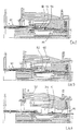
- the enhanced operating head (66) in question comprises a shaped forming drift (55), whereon a terminal portion (50) of the pipe (51) is fitted, comprising a first anterior portion (551) whose nominal diameter corresponds to that of the pipe (51) and a second portion (552) consecutive to the first and with greater nominal diameter, corresponding to the one to be obtained on the formed portion (50).
- the drift (55) is provided with conduits (58), exiting from its own lateral surface (81), for feeding a first pressurised fluid provided for carrying out a first outward dilation phase of the end portion (50) of the pipe (51).
- the head (66) also comprises at least two half-moulds (52), surrounding the drift (55) and movable from a first position distanced from the drift (55), in which their cavity (80) receives (Fig. 1) or releases (Fig. 6) the end portion (50) of the pipe (51), to a second position, closed on the drift (55) - see Figs. 2, 3, 4 and 5.
- the half-moulds (52), which limit the first dilation phase comprise an inner surface (53) shaped according to the outer shape of the formed terminal portion, also comprising a radial cavity (56), able to delimit externally the shape of the annular seat (500) which the terminal portion (50) of the pipe (51) will comprise after the shaping, for the stable placement of a sealing gasket (11).
- the half-moulds comprise conduits (54) for a second pressurised fluid provided for performing a second phase of forced radial contraction towards the drift (55), of the same terminal portion (50) of the pipe (51), after the first dilation phase.
- the half-moulds (52), the drift (55) and the flange (60) together and peripherally determine a first pressurisation chamber (Fig. 2) able to allow the first dilation phase, positioned between the lateral surface (81) of the drift (55) and the inner surface (83) of the pipe (51), as well as a second pressurisation chamber (Fig. 3), able to allow the second contraction phase, positioned between the outer surface (84) of the pipe (51) and the inner surface (53) of the die (52).
- Suitable sealing elements (59) are destined to interact both with the inner surface (83) and with the outer surface (84) of the terminal portion (50) of the pipe (51). They are located respectively both on the lateral surface (81) of the drift (55), and on the inner surface (53) of the half-moulds (52), allowing the pipe (51) to be inserted in a sealed manner into the operating head (66).
- the operating head (66) of the invention is enhanced because it is able to operate with drifts (55) of the type comprising a seat (551) for the sealing gasket (11), therein preliminarily positioned in temporary fashion.
- the flange (60) mounted advantageously in a single piece and coaxially and slidingly relative to the drift (55) and to the half-moulds (52), has (Fig. 2) a frontal stop surface (82) of the edge (62) of the terminal portion (50) of the pipe (51), operating upon the completion of its insertion on the drift (55) and presents its own extremity (600), oriented towards the terminal portion (50) of the pipe (51), shaped at least according to a double step (602, 603).
- the thickness of said inner step (603) of the flange (60) is such as to assure, simultaneously, the exact pre-set measurement of the constant minimum diameter of the cylindrical seat (700) for receiving the edge (62) of the terminal portion (50) of the pipe (51) and the seated stability of the gasket (11).
- the flange (60) on the one hand effectively holds the gasket (11) and on the other determines the minimal dilation which the edge (62) of the terminal portion (50) of the pipe must undergo, thereby establishing a precise minimum dilation limit for the edge (62), which thus allows an equally precise dimensional stabilisation of the extreme edge of the portion (50), which is the most difficult one to stabilise.
- the flange (60) moves backwards (Figs. 4 and 5), until the edge (62) is completely released from the flange and in particular from the underlying step (603), rapidly contracting and adhering onto the shaped surface of the underlying drift (55) and the half-moulds (52) reopen, for a new cycle.
- the flange (60) is subjected to a heating system (90) concentrated in correspondence with its own extremity (600) which is in direct contact with the terminal portion (50) of the pipe (51), able to be activated at least during the phase whereby the terminal portion (50) of the pipe (51) is introduced on the drift (55).
- This concentrated heating system (90) entails a forced circulation of a heated fluid inside the flange (60), which transfers heat concentrated exclusively in correspondence with the extremity (600) of the flange (60).
- the concentrated heating system (90) develops along a cylindrical segment (93) of the flange (60), internally provided with at least a first longitudinal seat (91) for a first corresponding ducting (910) ending, in correspondence with the free end of the same cylindrical segment, into at least a second annular ducting (920), which in turn is seated in a second circumferential seating (92).
- the latter is delimited and closed by a cover (94) coinciding with said extremity (600) of the flange (60).
- This cover (94) is preferably able to be associated in sealed fashion with said cylindrical segment (93) by means of simple screwing-on along a corresponding thread (96).
- the ducts are travelled by a heated fluid (preferably air), distributed directly and uniformly on the extremity (600) of the flange (60), through a plurality of small holes (921) obtained circumferentially on the second annular ducting (920), in the direction of the extremity (600) of the flange (60).
- a heated fluid preferably air
- the extremity (600) of the flange (60) preferably presents a third step (601) exterior to the other two, able to recover the total size of the thickness of the cylindrical segment (93) of the flange (60), containing said seats and ducts.
- the seal of the first pressurisation chamber (63), in correspondence with the edge (62), is achieved directly by the edge itself
- the seal of the second pressurisation chamber (64) is achieved by additional sealing gaskets (590), positioned in correspondence with the shaped surface (53) of the half-moulds (52) and interacting with the outer surface of the cylindrical segment (93).
Landscapes
- Engineering & Computer Science (AREA)
- Mechanical Engineering (AREA)
- Shaping Of Tube Ends By Bending Or Straightening (AREA)
- Moulds For Moulding Plastics Or The Like (AREA)
- Shaping Metal By Deep-Drawing, Or The Like (AREA)
Priority Applications (5)
| Application Number | Priority Date | Filing Date | Title |
|---|---|---|---|
| DK00830246T DK1138466T3 (da) | 2000-03-31 | 2000-03-31 | Arbejdshoved med trykfluid til automatiske muffeformningsmaskiner til permanent tilvejebringelse af en muffeform med pakning på terminale partier af plaströr |
| PT00830246T PT1138466E (pt) | 2000-03-31 | 2000-03-31 | Cabeçote de fluido pressurizável para máquinas automáticas de abocardar, para proporcionar a parcelas terminais de tubos de plástico, de uma forma permanente, uma forma abocardada com junta |
| DE60033912T DE60033912T2 (de) | 2000-03-31 | 2000-03-31 | Formwerkzeug mit Druckmittel, für automatische Muffenformmaschinen, zum bleibenden Formen von Muffen mit Dichtung an Kunststoff-Rohrenden |
| EP00830246A EP1138466B1 (de) | 2000-03-31 | 2000-03-31 | Formwerkzeug mit Druckmittel, für automatische Muffenformmaschinen, zum bleibenden Formen von Muffen mit Dichtung an Kunststoff-Rohrenden |
| AT00830246T ATE356710T1 (de) | 2000-03-31 | 2000-03-31 | Formwerkzeug mit druckmittel, für automatische muffenformmaschinen, zum bleibenden formen von muffen mit dichtung an kunststoff-rohrenden |
Applications Claiming Priority (1)
| Application Number | Priority Date | Filing Date | Title |
|---|---|---|---|
| EP00830246A EP1138466B1 (de) | 2000-03-31 | 2000-03-31 | Formwerkzeug mit Druckmittel, für automatische Muffenformmaschinen, zum bleibenden Formen von Muffen mit Dichtung an Kunststoff-Rohrenden |
Publications (2)
| Publication Number | Publication Date |
|---|---|
| EP1138466A1 true EP1138466A1 (de) | 2001-10-04 |
| EP1138466B1 EP1138466B1 (de) | 2007-03-14 |
Family
ID=8175270
Family Applications (1)
| Application Number | Title | Priority Date | Filing Date |
|---|---|---|---|
| EP00830246A Expired - Lifetime EP1138466B1 (de) | 2000-03-31 | 2000-03-31 | Formwerkzeug mit Druckmittel, für automatische Muffenformmaschinen, zum bleibenden Formen von Muffen mit Dichtung an Kunststoff-Rohrenden |
Country Status (5)
| Country | Link |
|---|---|
| EP (1) | EP1138466B1 (de) |
| AT (1) | ATE356710T1 (de) |
| DE (1) | DE60033912T2 (de) |
| DK (1) | DK1138466T3 (de) |
| PT (1) | PT1138466E (de) |
Citations (3)
| Publication number | Priority date | Publication date | Assignee | Title |
|---|---|---|---|---|
| US3929958A (en) * | 1971-04-26 | 1975-12-30 | Rieber & Son Plastic Ind As | Process for producing radially-expanded socket ends on thermoplastic pipe lengths |
| JPS6031945A (ja) * | 1983-07-29 | 1985-02-18 | Sekisui Chem Co Ltd | 合成樹脂管体の拡径受口部成形方法 |
| EP0700771A1 (de) * | 1994-08-23 | 1996-03-13 | S.I.C.A. SERRANDE INFISSI CARPENTERIA ATTREZZATURA S.p.A. | Formwerkzeug mit Druckmittel, für automatische Muffenformmaschinen, zum bleibenden Formen von Muffen an Kunststoff-Rohrenden |
-
2000
- 2000-03-31 DE DE60033912T patent/DE60033912T2/de not_active Expired - Lifetime
- 2000-03-31 DK DK00830246T patent/DK1138466T3/da active
- 2000-03-31 PT PT00830246T patent/PT1138466E/pt unknown
- 2000-03-31 EP EP00830246A patent/EP1138466B1/de not_active Expired - Lifetime
- 2000-03-31 AT AT00830246T patent/ATE356710T1/de active
Patent Citations (3)
| Publication number | Priority date | Publication date | Assignee | Title |
|---|---|---|---|---|
| US3929958A (en) * | 1971-04-26 | 1975-12-30 | Rieber & Son Plastic Ind As | Process for producing radially-expanded socket ends on thermoplastic pipe lengths |
| JPS6031945A (ja) * | 1983-07-29 | 1985-02-18 | Sekisui Chem Co Ltd | 合成樹脂管体の拡径受口部成形方法 |
| EP0700771A1 (de) * | 1994-08-23 | 1996-03-13 | S.I.C.A. SERRANDE INFISSI CARPENTERIA ATTREZZATURA S.p.A. | Formwerkzeug mit Druckmittel, für automatische Muffenformmaschinen, zum bleibenden Formen von Muffen an Kunststoff-Rohrenden |
Also Published As
| Publication number | Publication date |
|---|---|
| PT1138466E (pt) | 2007-05-31 |
| DE60033912T2 (de) | 2007-11-29 |
| DK1138466T3 (da) | 2007-07-02 |
| ATE356710T1 (de) | 2007-04-15 |
| EP1138466B1 (de) | 2007-03-14 |
| DE60033912D1 (de) | 2007-04-26 |
Similar Documents
| Publication | Publication Date | Title |
|---|---|---|
| MX161432A (es) | Metodo para hacer un acoplamiento de tubo y producto resultante | |
| US3899565A (en) | Method for forming tube with thickened socket end | |
| FI884353A7 (fi) | Foerfarande och anordning foer extrudering av ett plastroer. | |
| JPS63154314A (ja) | 射出成形方法及びこの方法によるプラスティック部品 | |
| DK0743159T3 (da) | Med sideindløb forsynet sprøjtestøbeapparat med radialt monterede indløbsindsatser | |
| CA2190569A1 (en) | Injection molding nozzle with edge gate inserts and sealing ring | |
| US4150087A (en) | Tube of thermoplastics with thickened end | |
| FI111524B (fi) | Paineväliainetoiminen työväline muoviputkien päätyalueiden pysyvien muhvien muodostamiseksi käytettäväksi automaattisessa muhvinmuodostuskoneessa | |
| US4428899A (en) | Method of making socketed pipe-fittings of synthetic plastics material by injection moulding, apparatus for carrying out said method | |
| EP1138466B1 (de) | Formwerkzeug mit Druckmittel, für automatische Muffenformmaschinen, zum bleibenden Formen von Muffen mit Dichtung an Kunststoff-Rohrenden | |
| CA2149387A1 (en) | Injection molding hot tip side gate seal with circumferential rim | |
| PT930148E (pt) | Metodo e aparelho para expandir e conferir uma forma de taca ao segmento da uniao de tubos orientados biaxialmente feitos de material termoplastico | |
| CA2363544C (en) | Two-piece injection molding nozzle seal | |
| JPS55124627A (en) | Production of compound molded body | |
| SE8203837L (sv) | Forfarande for att festa en liten tilleggstank in i en storre plasttank under tillverkningsprocessen | |
| JPS5854973B2 (ja) | マガリカンノブロ−セイケイホウ | |
| EP0842755A4 (de) | Verfahren und vorrichtung zur verarbeitung von tubenbehältern | |
| JP2000512227A (ja) | プラスチツク管の端部スリーブの製造方法及びこの方法を実施する装置 | |
| EP0800911B1 (de) | Werkzeug zum automatischen Formen, an Kunststoffrohren, von Muffen grosser Länge | |
| JPS6178620A (ja) | 二重構造品の成形方法及びそれに用いる真空,加熱装置 | |
| JPH0761670B2 (ja) | 金型表面加熱装置 | |
| CA2039300C (en) | Process for lining a tube | |
| JPS5660212A (en) | Molding method for socket of thermoplastic synthetic resin pipe | |
| JPS56126115A (en) | Secondary forming method of diametrically expanded socket having annular groove | |
| IT1242702B (it) | Procedimento e apparecchiatura per la realizzazione di tubi sagomati in materiale plasticotubi cosi' ottenuti |
Legal Events
| Date | Code | Title | Description |
|---|---|---|---|
| PUAI | Public reference made under article 153(3) epc to a published international application that has entered the european phase |
Free format text: ORIGINAL CODE: 0009012 |
|
| AK | Designated contracting states |
Kind code of ref document: A1 Designated state(s): AT BE CH CY DE DK ES FI FR GB GR IE IT LI LU MC NL PT SE |
|
| AX | Request for extension of the european patent |
Free format text: AL;LT;LV;MK;RO;SI |
|
| 17P | Request for examination filed |
Effective date: 20020218 |
|
| AKX | Designation fees paid |
Free format text: AT BE CH CY DE DK ES FI FR GB GR IE IT LI LU MC NL PT SE |
|
| 17Q | First examination report despatched |
Effective date: 20030930 |
|
| GRAP | Despatch of communication of intention to grant a patent |
Free format text: ORIGINAL CODE: EPIDOSNIGR1 |
|
| GRAS | Grant fee paid |
Free format text: ORIGINAL CODE: EPIDOSNIGR3 |
|
| GRAA | (expected) grant |
Free format text: ORIGINAL CODE: 0009210 |
|
| AK | Designated contracting states |
Kind code of ref document: B1 Designated state(s): AT BE CH CY DE DK ES FI FR GB GR IE IT LI LU MC NL PT SE |
|
| PG25 | Lapsed in a contracting state [announced via postgrant information from national office to epo] |
Ref country code: CH Free format text: LAPSE BECAUSE OF FAILURE TO SUBMIT A TRANSLATION OF THE DESCRIPTION OR TO PAY THE FEE WITHIN THE PRESCRIBED TIME-LIMIT Effective date: 20070314 Ref country code: LI Free format text: LAPSE BECAUSE OF FAILURE TO SUBMIT A TRANSLATION OF THE DESCRIPTION OR TO PAY THE FEE WITHIN THE PRESCRIBED TIME-LIMIT Effective date: 20070314 |
|
| REG | Reference to a national code |
Ref country code: GB Ref legal event code: FG4D |
|
| REG | Reference to a national code |
Ref country code: CH Ref legal event code: EP |
|
| REF | Corresponds to: |
Ref document number: 60033912 Country of ref document: DE Date of ref document: 20070426 Kind code of ref document: P |
|
| REG | Reference to a national code |
Ref country code: IE Ref legal event code: FG4D |
|
| REG | Reference to a national code |
Ref country code: PT Ref legal event code: SC4A Free format text: AVAILABILITY OF NATIONAL TRANSLATION Effective date: 20070517 |
|
| PG25 | Lapsed in a contracting state [announced via postgrant information from national office to epo] |
Ref country code: ES Free format text: LAPSE BECAUSE OF FAILURE TO SUBMIT A TRANSLATION OF THE DESCRIPTION OR TO PAY THE FEE WITHIN THE PRESCRIBED TIME-LIMIT Effective date: 20070625 |
|
| REG | Reference to a national code |
Ref country code: DK Ref legal event code: T3 |
|
| REG | Reference to a national code |
Ref country code: SE Ref legal event code: TRGR |
|
| REG | Reference to a national code |
Ref country code: CH Ref legal event code: PL |
|
| EN | Fr: translation not filed | ||
| EN | Fr: translation not filed | ||
| PLBE | No opposition filed within time limit |
Free format text: ORIGINAL CODE: 0009261 |
|
| STAA | Information on the status of an ep patent application or granted ep patent |
Free format text: STATUS: NO OPPOSITION FILED WITHIN TIME LIMIT |
|
| PG25 | Lapsed in a contracting state [announced via postgrant information from national office to epo] |
Ref country code: MC Free format text: LAPSE BECAUSE OF NON-PAYMENT OF DUE FEES Effective date: 20070331 |
|
| 26N | No opposition filed |
Effective date: 20071217 |
|
| GBPC | Gb: european patent ceased through non-payment of renewal fee |
Effective date: 20070614 |
|
| PG25 | Lapsed in a contracting state [announced via postgrant information from national office to epo] |
Ref country code: FR Free format text: LAPSE BECAUSE OF FAILURE TO SUBMIT A TRANSLATION OF THE DESCRIPTION OR TO PAY THE FEE WITHIN THE PRESCRIBED TIME-LIMIT Effective date: 20071102 Ref country code: GR Free format text: LAPSE BECAUSE OF FAILURE TO SUBMIT A TRANSLATION OF THE DESCRIPTION OR TO PAY THE FEE WITHIN THE PRESCRIBED TIME-LIMIT Effective date: 20070615 |
|
| PG25 | Lapsed in a contracting state [announced via postgrant information from national office to epo] |
Ref country code: GB Free format text: LAPSE BECAUSE OF NON-PAYMENT OF DUE FEES Effective date: 20070614 Ref country code: IE Free format text: LAPSE BECAUSE OF NON-PAYMENT OF DUE FEES Effective date: 20070402 |
|
| PG25 | Lapsed in a contracting state [announced via postgrant information from national office to epo] |
Ref country code: FR Free format text: LAPSE BECAUSE OF FAILURE TO SUBMIT A TRANSLATION OF THE DESCRIPTION OR TO PAY THE FEE WITHIN THE PRESCRIBED TIME-LIMIT Effective date: 20070314 |
|
| PGFP | Annual fee paid to national office [announced via postgrant information from national office to epo] |
Ref country code: DK Payment date: 20090313 Year of fee payment: 10 |
|
| PGFP | Annual fee paid to national office [announced via postgrant information from national office to epo] |
Ref country code: FI Payment date: 20090316 Year of fee payment: 10 Ref country code: PT Payment date: 20090326 Year of fee payment: 10 |
|
| PG25 | Lapsed in a contracting state [announced via postgrant information from national office to epo] |
Ref country code: CY Free format text: LAPSE BECAUSE OF FAILURE TO SUBMIT A TRANSLATION OF THE DESCRIPTION OR TO PAY THE FEE WITHIN THE PRESCRIBED TIME-LIMIT Effective date: 20070314 |
|
| PG25 | Lapsed in a contracting state [announced via postgrant information from national office to epo] |
Ref country code: LU Free format text: LAPSE BECAUSE OF NON-PAYMENT OF DUE FEES Effective date: 20070331 |
|
| PGFP | Annual fee paid to national office [announced via postgrant information from national office to epo] |
Ref country code: BE Payment date: 20090401 Year of fee payment: 10 |
|
| BERE | Be: lapsed |
Owner name: SICA S.P.A. Effective date: 20100331 |
|
| REG | Reference to a national code |
Ref country code: DK Ref legal event code: EBP |
|
| PG25 | Lapsed in a contracting state [announced via postgrant information from national office to epo] |
Ref country code: FI Free format text: LAPSE BECAUSE OF NON-PAYMENT OF DUE FEES Effective date: 20100331 |
|
| PG25 | Lapsed in a contracting state [announced via postgrant information from national office to epo] |
Ref country code: PT Free format text: LAPSE BECAUSE OF NON-PAYMENT OF DUE FEES Effective date: 20100930 |
|
| PG25 | Lapsed in a contracting state [announced via postgrant information from national office to epo] |
Ref country code: BE Free format text: LAPSE BECAUSE OF NON-PAYMENT OF DUE FEES Effective date: 20100331 |
|
| PG25 | Lapsed in a contracting state [announced via postgrant information from national office to epo] |
Ref country code: DK Free format text: LAPSE BECAUSE OF NON-PAYMENT OF DUE FEES Effective date: 20100331 |
|
| PGFP | Annual fee paid to national office [announced via postgrant information from national office to epo] |
Ref country code: NL Payment date: 20180323 Year of fee payment: 19 |
|
| PGFP | Annual fee paid to national office [announced via postgrant information from national office to epo] |
Ref country code: AT Payment date: 20180328 Year of fee payment: 19 Ref country code: SE Payment date: 20180327 Year of fee payment: 19 |
|
| PGFP | Annual fee paid to national office [announced via postgrant information from national office to epo] |
Ref country code: DE Payment date: 20180530 Year of fee payment: 19 |
|
| PGFP | Annual fee paid to national office [announced via postgrant information from national office to epo] |
Ref country code: IT Payment date: 20180326 Year of fee payment: 19 |
|
| REG | Reference to a national code |
Ref country code: DE Ref legal event code: R119 Ref document number: 60033912 Country of ref document: DE |
|
| REG | Reference to a national code |
Ref country code: NL Ref legal event code: MM Effective date: 20190401 |
|
| REG | Reference to a national code |
Ref country code: AT Ref legal event code: MM01 Ref document number: 356710 Country of ref document: AT Kind code of ref document: T Effective date: 20190331 |
|
| REG | Reference to a national code |
Ref country code: SE Ref legal event code: EUG |
|
| PG25 | Lapsed in a contracting state [announced via postgrant information from national office to epo] |
Ref country code: SE Free format text: LAPSE BECAUSE OF NON-PAYMENT OF DUE FEES Effective date: 20190401 Ref country code: AT Free format text: LAPSE BECAUSE OF NON-PAYMENT OF DUE FEES Effective date: 20190331 Ref country code: DE Free format text: LAPSE BECAUSE OF NON-PAYMENT OF DUE FEES Effective date: 20191001 Ref country code: NL Free format text: LAPSE BECAUSE OF NON-PAYMENT OF DUE FEES Effective date: 20190401 |
|
| PG25 | Lapsed in a contracting state [announced via postgrant information from national office to epo] |
Ref country code: IT Free format text: LAPSE BECAUSE OF NON-PAYMENT OF DUE FEES Effective date: 20190331 |