EP1138629A2 - Micropuce pour distribution de solutions acqueuses et méthode d'utilisation - Google Patents
Micropuce pour distribution de solutions acqueuses et méthode d'utilisation Download PDFInfo
- Publication number
- EP1138629A2 EP1138629A2 EP01302834A EP01302834A EP1138629A2 EP 1138629 A2 EP1138629 A2 EP 1138629A2 EP 01302834 A EP01302834 A EP 01302834A EP 01302834 A EP01302834 A EP 01302834A EP 1138629 A2 EP1138629 A2 EP 1138629A2
- Authority
- EP
- European Patent Office
- Prior art keywords
- aqueous
- distribution
- phase
- channel
- microchip
- Prior art date
- Legal status (The legal status is an assumption and is not a legal conclusion. Google has not performed a legal analysis and makes no representation as to the accuracy of the status listed.)
- Withdrawn
Links
Images



Classifications
-
- G—PHYSICS
- G01—MEASURING; TESTING
- G01N—INVESTIGATING OR ANALYSING MATERIALS BY DETERMINING THEIR CHEMICAL OR PHYSICAL PROPERTIES
- G01N15/00—Investigating characteristics of particles; Investigating permeability, pore-volume or surface-area of porous materials
- G01N15/10—Investigating individual particles
- G01N15/14—Optical investigation techniques, e.g. flow cytometry
- G01N15/1404—Handling flow, e.g. hydrodynamic focusing
-
- B—PERFORMING OPERATIONS; TRANSPORTING
- B01—PHYSICAL OR CHEMICAL PROCESSES OR APPARATUS IN GENERAL
- B01L—CHEMICAL OR PHYSICAL LABORATORY APPARATUS FOR GENERAL USE
- B01L3/00—Containers or dishes for laboratory use, e.g. laboratory glassware; Droppers
- B01L3/50—Containers for the purpose of retaining a material to be analysed, e.g. test tubes
- B01L3/502—Containers for the purpose of retaining a material to be analysed, e.g. test tubes with fluid transport, e.g. in multi-compartment structures
- B01L3/5027—Containers for the purpose of retaining a material to be analysed, e.g. test tubes with fluid transport, e.g. in multi-compartment structures by integrated microfluidic structures, i.e. dimensions of channels and chambers are such that surface tension forces are important, e.g. lab-on-a-chip
- B01L3/502769—Containers for the purpose of retaining a material to be analysed, e.g. test tubes with fluid transport, e.g. in multi-compartment structures by integrated microfluidic structures, i.e. dimensions of channels and chambers are such that surface tension forces are important, e.g. lab-on-a-chip characterised by multiphase flow arrangements
- B01L3/502776—Containers for the purpose of retaining a material to be analysed, e.g. test tubes with fluid transport, e.g. in multi-compartment structures by integrated microfluidic structures, i.e. dimensions of channels and chambers are such that surface tension forces are important, e.g. lab-on-a-chip characterised by multiphase flow arrangements specially adapted for focusing or laminating flows
-
- B—PERFORMING OPERATIONS; TRANSPORTING
- B01—PHYSICAL OR CHEMICAL PROCESSES OR APPARATUS IN GENERAL
- B01L—CHEMICAL OR PHYSICAL LABORATORY APPARATUS FOR GENERAL USE
- B01L2200/00—Solutions for specific problems relating to chemical or physical laboratory apparatus
- B01L2200/06—Fluid handling related problems
- B01L2200/0636—Focussing flows, e.g. to laminate flows
-
- B—PERFORMING OPERATIONS; TRANSPORTING
- B01—PHYSICAL OR CHEMICAL PROCESSES OR APPARATUS IN GENERAL
- B01L—CHEMICAL OR PHYSICAL LABORATORY APPARATUS FOR GENERAL USE
- B01L2300/00—Additional constructional details
- B01L2300/08—Geometry, shape and general structure
- B01L2300/0809—Geometry, shape and general structure rectangular shaped
- B01L2300/0816—Cards, e.g. flat sample carriers usually with flow in two horizontal directions
-
- B—PERFORMING OPERATIONS; TRANSPORTING
- B01—PHYSICAL OR CHEMICAL PROCESSES OR APPARATUS IN GENERAL
- B01L—CHEMICAL OR PHYSICAL LABORATORY APPARATUS FOR GENERAL USE
- B01L2300/00—Additional constructional details
- B01L2300/08—Geometry, shape and general structure
- B01L2300/0861—Configuration of multiple channels and/or chambers in a single devices
- B01L2300/0864—Configuration of multiple channels and/or chambers in a single devices comprising only one inlet and multiple receiving wells, e.g. for separation, splitting
-
- B—PERFORMING OPERATIONS; TRANSPORTING
- B01—PHYSICAL OR CHEMICAL PROCESSES OR APPARATUS IN GENERAL
- B01L—CHEMICAL OR PHYSICAL LABORATORY APPARATUS FOR GENERAL USE
- B01L3/00—Containers or dishes for laboratory use, e.g. laboratory glassware; Droppers
- B01L3/50—Containers for the purpose of retaining a material to be analysed, e.g. test tubes
- B01L3/502—Containers for the purpose of retaining a material to be analysed, e.g. test tubes with fluid transport, e.g. in multi-compartment structures
- B01L3/5027—Containers for the purpose of retaining a material to be analysed, e.g. test tubes with fluid transport, e.g. in multi-compartment structures by integrated microfluidic structures, i.e. dimensions of channels and chambers are such that surface tension forces are important, e.g. lab-on-a-chip
- B01L3/502761—Containers for the purpose of retaining a material to be analysed, e.g. test tubes with fluid transport, e.g. in multi-compartment structures by integrated microfluidic structures, i.e. dimensions of channels and chambers are such that surface tension forces are important, e.g. lab-on-a-chip specially adapted for handling suspended solids or molecules independently from the bulk fluid flow, e.g. for trapping or sorting beads or physically stretching molecules
-
- G—PHYSICS
- G01—MEASURING; TESTING
- G01N—INVESTIGATING OR ANALYSING MATERIALS BY DETERMINING THEIR CHEMICAL OR PHYSICAL PROPERTIES
- G01N15/00—Investigating characteristics of particles; Investigating permeability, pore-volume or surface-area of porous materials
- G01N15/10—Investigating individual particles
- G01N15/14—Optical investigation techniques, e.g. flow cytometry
- G01N15/149—Optical investigation techniques, e.g. flow cytometry specially adapted for sorting particles, e.g. by their size or optical properties
-
- G—PHYSICS
- G01—MEASURING; TESTING
- G01N—INVESTIGATING OR ANALYSING MATERIALS BY DETERMINING THEIR CHEMICAL OR PHYSICAL PROPERTIES
- G01N1/00—Sampling; Preparing specimens for investigation
- G01N1/28—Preparing specimens for investigation including physical details of (bio-)chemical methods covered elsewhere, e.g. G01N33/50, C12Q
- G01N1/40—Concentrating samples
- G01N1/4005—Concentrating samples by transferring a selected component through a membrane
- G01N2001/4016—Concentrating samples by transferring a selected component through a membrane being a selective membrane, e.g. dialysis or osmosis
-
- G—PHYSICS
- G01—MEASURING; TESTING
- G01N—INVESTIGATING OR ANALYSING MATERIALS BY DETERMINING THEIR CHEMICAL OR PHYSICAL PROPERTIES
- G01N1/00—Sampling; Preparing specimens for investigation
- G01N1/28—Preparing specimens for investigation including physical details of (bio-)chemical methods covered elsewhere, e.g. G01N33/50, C12Q
- G01N1/40—Concentrating samples
- G01N1/4055—Concentrating samples by solubility techniques
- G01N2001/4061—Solvent extraction
-
- G—PHYSICS
- G01—MEASURING; TESTING
- G01N—INVESTIGATING OR ANALYSING MATERIALS BY DETERMINING THEIR CHEMICAL OR PHYSICAL PROPERTIES
- G01N15/00—Investigating characteristics of particles; Investigating permeability, pore-volume or surface-area of porous materials
- G01N2015/0042—Investigating dispersion of solids
- G01N2015/0053—Investigating dispersion of solids in liquids, e.g. trouble
-
- G—PHYSICS
- G01—MEASURING; TESTING
- G01N—INVESTIGATING OR ANALYSING MATERIALS BY DETERMINING THEIR CHEMICAL OR PHYSICAL PROPERTIES
- G01N15/00—Investigating characteristics of particles; Investigating permeability, pore-volume or surface-area of porous materials
- G01N15/10—Investigating individual particles
- G01N15/14—Optical investigation techniques, e.g. flow cytometry
- G01N15/1404—Handling flow, e.g. hydrodynamic focusing
- G01N2015/1413—Hydrodynamic focussing
Definitions
- the present invention relates to a microchip for aqueous distribution and a method of aqueous distribution using such microchip, and more particularly to a microchip for aqueous distribution used suitably in distributing micro-substances, for example, particles, molecules and the like such as cells, organelles, proteins, and nucleic acids as well as a method of aqueous distribution using such microchip.
- micro-substances for example, particles, molecules and the like such as cells, organelles, proteins, and nucleic acids
- micro-substances for example, particles, molecules and the like such as cells, organelles, proteins, and nucleic acids
- a specific example of the micro-substances includes microorganisms such as Escherichia coli, and yeast; a variety of cultivated cells of plants and animals; organelles such as mitochondrion, and chloroplast; proteins such as albumin, insulin; and nucleic ac ids such as DNA, and RNA.
- micro-substances for example, particles, molecules and the 1 ike such as cells, organelles, proteins, and nucleic acids
- a technology for distributing micro-substances for example, particles, molecules and the 1 ike such as cells, organelles, proteins, and nucleic acids has been recognized as an important technique in not only fundamental research, but also in a field of medical diagnosis and the like.
- Aqueous two-phase distribution method is a technique including two steps wherein an aqueous two-phase system consisting of, for example, an aqueous solution of polyethylene glycol (PEG) and an aqueous solution of dextran are prepared, these two phases of aqueous solutions are blended with each other to transfer substances contained therein, and thereafter both the phases of aqueous solutions are separated into two phases of the top phase and the bottom phase.
- PEG polyethylene glycol
- the above-described micro-substances such as cells can be distributed into the top phase, the bottom phase, and their phase boundary (interface) dependent upon differences in sizes, surface charges, hydrophilic-hydrophob ic characteristic of the micro-substances, whereby high-volume processing of the micro-substances can be attained under a moderate condition, so that this method is excellent in this respect.
- a conventional aqueous two-phase distribution method involves such a problem in that a long period of time is required for separating aqueous solutions of two phases having close physical properties, so that the whole processing period of time becomes prolonged.
- the present invention has been made in view of such problems involved in the prior art as described above, and an object of the invention is to provide a microchip for aqueous distribution by which a processing period of time can be reduced in case of processing distribution of micro-substances, for example, particles, molecules and the like such as cells, organelles, proteins, and nucleic acids as well as to provide a method of aqueous distribution using the microchip thus obtained.
- micro-substances for example, particles, molecules and the like such as cells, organelles, proteins, and nucleic acids
- another object of the present invention is to provide a microchip for aqueous distribution used suitably for processing distribution of micro-substances, for example, particles, molecules and the like such as cells, organelles, proteins, and nucleic acids in a multistage manner as well as to provide a method of aqueous distribution using the microchip thus obtained.
- micro-substances for example, particles, molecules and the like such as cells, organelles, proteins, and nucleic acids
- Still another object of the present invention is to provide a microchip for aqueous distribution used suitably for processing distribution of micro-substances, for example, particles, molecules and the like such as cells, organelles, proteins, and nucleic acids in an automated manner as well as to provide a method of aqueous distribution using the microchip thus obtained.
- micro-substances for example, particles, molecules and the like such as cells, organelles, proteins, and nucleic acids
- an expression "an aqueous multi-phase of an aqueous two-phase system containing aqueous two phases wherein a variety of aqueous solutions are used, or three-, and more-phases" is referred optionally to as "an aqueous composite phase”
- an expression "an aqueous multi-phase distribution system of an aqueous two-phase system containing aqueous two phases wherein a variety of aqueous solutions are used, or three-, and more-phase systems” is referred optionally to as "an aqueous composite phase”
- an expression "an aqueous multi-phase distribution system of an aqueous two-phase system containing aqueous two phases wherein a variety of aqueous solutions are used, or three-, and more-phase systems” is referred optionally to as "an aqueous composite phase distribution system” dependent upon differences in sizes, surface charges, hydrophilic-hydrophobic
- a stable a queous composite phase distribution system is constructed inside a micro channel defined on a microchip for aqueous distribution, and when aqueous solutions in the respective phases are transferred respectively inside the micro channel, it becomes possible to distribute continuously micro-substances, for example, particles, molecules and the like such as cells, organelles, proteins, and nucleic acids in an interface having a large area per volume so as to increase an interfacial area per volume of an aqueous solution in respective phases without mixing any aqueous solution in the respective phases.
- micro-substances for example, particles, molecules and the like such as cells, organelles, proteins, and nucleic acids
- a constitution of the present invention comprises a micro channel having a predetermined shape, which is defined on a flat plate substrate; and a plurality of branched channels, each of which has a predetermined shape and is defined on the substrate, besides these branched channels are linked to only either end of the micro channel.
- a constitution of the present invention comprises a micro channel having a predetermined shape, which is defined on a flat plate substrate; a plurality of branched channels, each of which has a predetermined shape and is defined on the substrate, besides these branched channels are linked to either end of the micro channel; and a plurality of branched channels, each of which has a predetermined shape and is defined on the substrate, besides these branched channels are linked to the other end of the micro channel.
- the number of the plurality of branched channels linked to either end of the micr o channel may conform to the number of the plurality of branched channels linked to the other end of the micro channel.
- the number of the plurality of branched channels linked to either end of the micr o channel may differ from the number of the plurality of branched channels linked to the other end of the micro channel.
- the above-described constitution comprises further, a flat surface plate disposed on the top of the substrate; and the micro channel as well as the plurality of branched channels, which are defined on the top of the substrate being sealed with the surface plate.
- a constitution of the invention comprises the steps of supplying an aqueous solution in each phase, which is phase-separated to each of the branched channels; and distr ibuting micro-substances incorporated in the aqueous solution into each phase while transferring the aqueous solution in a phase-separated state inside the micro channel.
- transferring directions of phases adjacent to each other through their interface are in a parallel flow where the directions are the same with each other in case of transferring the aqueous solution in a phase-separated state inside the micro channel.
- transferring directions of phases adjacent to each other through their interface are in a counter flow where the directions are reverse of one another in case of transferring the aqueous solution in a phase-separated state inside the micro channel.
- a parallel flow where directions of phases adjacent to each other through their interface are the same with each other, and a counter flow where transferring directions of phases adjacent to each other through their interface are reverse of one another exist mixedly in case of transferring the aqueous solution in a phase-separated state inside the micro channel.
- FIGS. 1a and 1b illustrate the first preferred embodiment of a microchip for aqueous distribution according to the present invention wherein FIG. 1a is a fragmentary view taken in the direction of the arrow A in FIG. 1b, and FIG. 1b is a sectional view taken along the line B-B in FIG. 1a.
- a microchip 10 for aqueous distribution is composed of a flat plate substrate 12 prepared from a high-molecular (polymer) material such as PDMS (polydimethyl siloxane), and a flat surface plate 14 prepared from PMMA (pol ymethyl methacrylate) disposed on a top 12a of the substrate 12.
- a high-molecular (polymer) material such as PDMS (polydimethyl siloxane)
- PMMA polymethyl methacrylate
- micro channel 16 configuring a straight-line type flow path having a so-called I-shape.
- One of the opposite ends of the micro channel 16 is bifurcated into a first branched channel 17a and a second branched channel 17b, while the other of the opposite ends of the micro channel 16 is also bifurcated into a third branched channel 17c and the fourth branched channel 17d.
- the micro channel 16, the first branched channel 17a, the second branched channel 17b, the third branched channel 17c, and the fourth branched channel 17d, which have been defined on the top 12a of the substrate 12 as described above are sealed with the surface plate 14.
- a first port 18a On the surface plate 14 are bored four ports, i.e., a first port 18a, a second port 18b, a third port 18c, and a fourth port 18d for introducing thereinto or discharging therefrom a variety of aqueous solutions for aqueous distribution, respectively, which function as openings and formed in such a manner that the openings penetrate the surface plate 14a from the top 14a to the bottom 14b thereof.
- the first port 18a, the second port 18b, the third port 18c, and the fourth port 18d as well as the first branched channel 17a, the second branched channel 17b, the third branched channel 17c, and the fourth branched channel 17d are disposed and defined, respectively, in such that an extreme end 17aa of the first branched channel 17a is 1 ocated at a part of the first port 18a, an extreme end 17bb of the second branched channel 17b is located at a part of the second port 18b, an extreme end 17cc of the third branched channel 17c is located at a part of the third port 18c, and an extreme end 17dd of the fourth branched channel 17d is located at a part of the fourth port 18d, whereby the first port 18a is communicated with the extreme end 17aa of the first branched channel 17a, the second port 18b is communicated with the extre me end 17bb of the second branched channel 17b, the third port 18c is
- a length L1 of the micro channel 16 is, for example, defined to be 10 mm
- a width W1 of the micro channel 16 is, for example, defined to be 400 im
- a depth D1 of the micro channel 16 is, for example, defined to be 180 im.
- each length L2 of the first branched channel 17a, the second branched channel 17b, the third branched channel 17c, and the fourth branched channel 17d is, for example, defined to be 5 mm
- each width W2 of the first branched channel 17a, the second branched channel 17b, the third branched channel 17c, and the fourth branched channel 17d is, for example, defined to be 200 im
- each depth D2 of the first branched channel 17a, the second branched channel 17b, the third branched channel 17c, and the fourth branched channel 17d is, for example, defined to be 180 im, respectively.
- the length L1 of the micro channel 16 as well as each of the lengths L2 of the first branched channel 17a, the second branched channel 17b, the third branched channel 17c, and the fourth branched channel 17d are not specifically restricted, but an arbitrary length may be selected as occasion demands, for instance, it is possible t o define these lengths L1 and L2 to be an optional value extending from 1 mm to 1000 mm, respectively.
- width Wl of the micro channel 16 as well as each of the widths W2 of the first branched channel 17a, the second branched channel 17b, the third branched channel 17c, and the fourth branched channel 17d are not specifically restr icted, but an arbitrary width may be selected as occasion arises, for instance, it is possible to define these widths to be an optional value extending from 1 im to 1000 im, respectively.
- the depth D1 of the micro channel 16 as well as each of the depths D2 of the first branched channel 17a, the second branched channel 17b, the third branched channel 17c, and the fourth branched channel 17d are not specifically restr icted, but an arbitrary depth may be selected according to needs, for instance, it is possible to define these depths to be an optional value extending from 1 im to 5 mm, respectively.
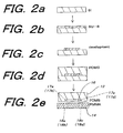
- the above-described microchip 10 for aqueous distr ibution may be manufactured in accordance with, for example, a manufacturing process, which will be described herein by referring to FIGS. 2a, 2b, 2c, 2d, and 2e, respectively.
- a layout pattern for forming the micro channel 16 has been printed on a transparent film with high resolution, e.g., 4064 dpi for the sake of utilizing the same as a mask for photolithography.
- a process for manufacturing the microchip 10 for aqueous distribution provided with the above-described substrate 12 prepared from PDMS will be described in detail hereinafter.
- FIGS. 2a, 2b, 2c, 2d, and 2e Outline of a manufacturing process for the microchip 10 for aqueous distribution is illustrated in FIGS. 2a, 2b, 2c, 2d, and 2e, respectively.
- a silicon (Si) wafer of 20 mm x 20 mm is dried in an oven (FIG. 2a), the silicon wafer thus dried is spin-coated with a negative photoresist SU-8 at 500 rpm for ten seconds and at 1500 rpm for ten seconds, and then the silicon wafer thus coated is lagged for 30 minutes in the oven at 90°C (FIG. 2b).
- a structure of the micro channel 16, the first branched channel 17a, the second branched channel 17b, the third branched channel 17c, and the fourth branched channel 17 having a depth of 180 im is fabricated in the first preferred embodiment.
- the layout pattern thus printed in a mask-shaped for the microchip 10 for aqueous distribution is transferred to a silicon wafer coated with SU-8 by the use of a mask aligner (for example, "PEM-800; Union Optical Co., Tokyo, Japan” may be used as a mask aligner) in accordance with a photolithographic manner, and the resulting layout pattern is developed by keeping the same in 1-methoxy-2-propyl acetic acid for twenty minutes (FIG. 2c).
- a mask aligner for example, "PEM-800; Union Optical Co., Tokyo, Japan” may be used as a mask aligner
- the master thus fabricated is washed with isopropyl alcohol, and succeedingly with distilled water.
- the master was treated with fluorocarbon by the use of RIE (Reactive Ion Etching) system.
- the fluorocarbon treatment is useful for removing a PDMS replica after templating.
- the PDMS prepolymer and a curing reagent (for example, "Sylgard 184: Dow Corning Co. , MI" may be used as a curing reagent) are blended in a ratio of "10 : 1", the mixture is sufficiently agitated, and then the mixture is vacuum-deaerated for only fifteen minutes to prepare a prepol ymer mixed liquor.
- the resulting prepolymer mixed liquor is p oured on the master, and the master thus poured is cured at 65°C for one hour, and then at 95°C for fifteen minutes (FIG. 2d).
- a PDMS substrate 12 is obtained. Then, the PMMA surface plate 14 on which have been bored the first port 18a, the second port 18b, the third port 18c, and the fourth port 18d is covered with the PDMS substrate 12 to be mounted thereon, whereby the micro channel 16, the first branched channel 17a, the second branched channel 17b, the third branched channel 17c, and the fourth branched channel 17d are sealed therewith (FIG. 2e)
- the micro channel 16, the first branched channel 17a, the second branched channel 17b, the third branched channel 17c, and the fourth branched channel 17d are sealed therewith
- the first port 18a is communicated with the extreme end 17aa of the first branched channel 17a
- the second port 18b is communicated with the extre me end 17bb of the second branched channel 17b
- the third port 18c is communicated with the extreme end 17cc of the third branched channel 17c
- the fourth port 18d is communicated with the extreme end 17dd of the fourth branched channel 17d, respectively.
- the PDMS substrate 12 attached to the PMMA surface plate 14 by means of RIE system is oxidized with oxygen plasma, whereby the micro channel 16, the first branched channel 17a, the second branched channel 17b, the third branched channel 17c, and the fourth branched channel 17d are oxidized with oxygen plasma, so that it is possible to make each surface of the micro channel 16, the first branched channel 17a, the second branched channel 17b, the third branched channel 17c, and the fourth branched channel 17d to be hydrophilic.
- a manner for making each surface of the micro channel 16, the first branched channel 17a, the second branched channel 17b, the third branched channel 17c, and the fourth branched channel 17d to be hydrophilic is not 1 imited to a manner for oxidizing each surface of them with oxygen plasma as described above, but other manners may be appropriately utilized.
- micro-substances for example, particles, molecules and the like such as cells, organelles, proteins, and nucleic acids
- an aqueous two-phase solution composed of, for example, polyethylene glycol and dextran, which is an aqueous two-phase solution that is adjusted so as to be capable of obtaining a stable aqueous two-phase system and that has been phase-separated must be first prepared.
- Lithium sulfate or the like may be added to the resulting aqueous solution as occasion demands.
- Micro-substances to be distributed are incorporated in both or either of a first phase of a polyethylene glycol rich a queous solution and a second phase of a dextran rich aqueous solution, both the aqueous solutions having been prepared and phase-separated as described above.
- both supply steps of the polyethylene glycol rich aqueous solution into the first branched channel 17 and the dextran rich aqueous solution into the second branched channel 17b may be started either exactly at the same time, or either of the suppl y steps of the aqueous solutions may be started first, and then the other supply step may be started after lapse of a predetermined time.
- such micro-substances may be introduced in an interface of these two phases in the form of a queous solution or suspension.
- the polyethylene glycol rich aqueous solution and the dextran rich aqueous solution proceed inside the micro channel 16 in a direction indicated by, for example, a solid line arrow C in a phase-separated condition wherein there are two phases of a polyethylene glycol rich phase 102 and a dextran rich phase 104 separated by an interface 100 as shown in FIG. 3.
- the polyethylene glycol rich phase 102 is in a state of parallel flow with respect to the dextran rich phase 104 in the micro channel 16.
- the micro-substances 200 which have been incorporated in both or either of the polyethylene glycol rich aqueous solution and the dextran rich aqueous solution transfer, for instance, from the polyethylene glycol rich phase 102 to the interface 100 or the dextran rich phase 104, otherwise the micro-substances transfer from the dextran rich phase 104 to the interface 100 or the polyethylene glycol rich phase 102 along the directions indicated by broken line arrows shown in FIG. 3 dependent upon differences in sizes, surface charges, hydrophilic-hydrophobic characteristic of the micro-substances, whereby distribution is carried out in response to properties of the micro-substances.
- a stable aqueous plural phase distributing system is formed in the micro channel 16 defined on the micro chip 10 for aqueous distribution, so that when the polyethylene glycol rich phase 102 and the dextran rich phase 104 transfer inside the micro channel 16, an interfacial area per volume of the polyethylene glycol rich phase 102 and the dextran rich phase 104 increases, and as a result, the micro-substances 200 can be continuously distributed in such interface where an area per volume is large without blending the polyethylene glycol rich aqueous solution with the dextran rich aqueous solution.
- the polyethylene glycol rich phase 102 which had transferred inside the micro channel 16 passes through the third branched channel 17c and flows out outside the micro chip 10 for aqueous distribution through the third port 18c, while the dextran rich phase 104, which had transferred inside the micro channel 16 passes through the fourth branched channel 17d and flows out outside the micro chip 10 for aqueous distribution through the fourth port 18d.
- polyethylene glycol rich phase 102 drained from the third port 18c and the dextran rich phase 104 drained from the fourth port 18d are used for purposes of appropriate analysis, recovery of cells and the like.
- the micro-substances 200 can be contin uously distributed, so that distribution efficiency is improved, whereby it becomes possible to reduce a treating time for distribution.
- the microchip 10 has a simple structure as described above, even if such a distribution system that is constituted by multiplying stages of a plurality of microchips 10 for aqueous distribution is manufactured, upsizing of the whole distribution system is avoided, whereby downsizing and s implification of the distribution system can be attained.
- the microchip 10 for aqueous distribution may be concluded to be suitably used for a multistage treatment for distributing the micro-substances 200.
- a treatment for aqueous distribution of the micro-substances 200 wherein the microchip 10 for aqueous distribution is used does not need any operation for complicated treatment, so that it may be concluded that the microchip 10 for aqueous distribution is suitable for automating operation for treatment.
- the polyethylene glycol rich aqueous solution has been introduced into the first branched channel 17a through the first port 18a, and at the same time, the dextran rich aqueous solution has been introduced into the second branched channel 17b through the second port 18b, thereafter, the polyethylene glycol rich phase 102, which had transferred inside the micro channel 16 has passed through the third branched channel 17c and has been drained to the micr allp 10 for aqueous distribution through the third port 18c, while the dextran rich phase 10, which had transferred inside the micro channel 16 has passed through the fourth branched channel 17d and has been drained to the microchip 10 for aqueous distribution through the fourth port 18d.
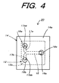
- a third branched channel 17c and a fourth branched channel 17d are not defined on a substrate 12, and both the polyethylene glycol rich phase 102 and the dextran rich phase 104, which had transferred inside the micro channel 16 is drained outside a microchip 20 for aqueous distribution through a port 18e (the port 18e communicates with an extreme end 16a of a micro channel 16 located on the side opposite to that where a first branched channel 17a is connected to a second branched channel 17b with an adjacent relation) that is defined on a surface plate 14 in place of a third port 18c and a fourth port 18d without defining a third branched channel 17c and a fourth branched channel 17d on the substrate 12 as in the microchip 20 for aqueous distribution being a second preferred embodiment of a microchip for aqueous distribution according t o the present invention shown
- microchip 20 for aqueous distribution shown in FIG. 4 the same components as or equivalent ones to those of the microchip 10 for aqueous distribution are represented by the same as or equivalent to the reference numerals used in FIG. 1a.
- aqueous distribution wherein the above-described microchip 10 for aqueous distribution has applied such parallel flow that the polyethylene glycol rich a queous solution is introduced into the first branched channel 17a through the first port 18a, and at the same time, the dextran rich aqueous solution is introduced into the second branched channel 17b through the second port 18b, whereby the polyethylene glycol rich phase 102 transfers in the same direction as that of the dextran rich phase 104 with respect to the interface 100, such counterflow that the polyethylene glycol rich phase 102 transfers in a direction opposite to that of the dextran rich phase 104 with respect to the interface 100 may also be applied to the aqueous distribution.
- the polyethylene glycol rich aqueous solution is introduced into the first branched channel 17a through the first port 18a (located in the upper left part of FIG. 1a), and at the same time, the dextran rich aqueous solution is introduced into the fourth branched channel 17d through the fourth port 18d (located in the lower right part of FIG. 1a).
- the polyethylene glycol rich aqueous solution introduced into the first branched channel 17a through the first port 18a transfers inside the micro channel 16 in a direction indicated by the arrow D (see FIG. 5) as the polyethylene glycol rich phase 102 with respect to the interface 100 to pass through the third branched channel 17c, and is drained outside the microchip 10 for aqueous distribution through the third port 18c
- the dextran rich aqueous solution introduced into the fourth branched channel 17d through the fourth port 17d transfers inside the micro channel 16 in a direction indicated by the arrow E (see FIG. 5) as the dextran rich phase 104 with respect to the interface 100 to pass through the second branched channel 17b, and is drained outside the microchip 10 for aqueous distribution thr ough the second port 18b.
- microchip 10 for aqueous distr ibution is suitably used for an aqueous two-phase distribution system
- the number of ports or branched channels required for introducing a variety of aqueous solutions into a micro channel may be selected in response to the number of phases questioned.
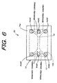
- the microchip when it is intended to use a microchip for aqueous distribution according to the present invention in an aqueous three-phase distribution system, the microchip may be constituted as in a microchip 30 for aqueous distribution being a third preferred embodiment of a microchip for aqueous solution according to the present invention shown in FIG. 6 in such that three each branched channels are defined in a micro channel 16 at both opposite ends thereof, besides ports in response to the three each branched channels are defined.
- micro channel 16 it may be arranged in such that parallel flow exists mixedly with counter flow in a single micro channel 16 as a matter of course.
- the number of ports and branched channels through which a variety of aqueous solutions are introduced into a micro channel 16 is not restricted as described above, for instance, it may be arranged in such that four each of branched channels, which are branched from the micro channel 16 at extreme end portions of the opposite ends thereof are defined, and further four each ports are defined in response to these four each of branched channels in the case where the number of phases for aqueous distribution is four, and in this connection, if the number of phases for aqueous distribution is five, it ma y be arranged in such that five each of branched channels, which are branched from the micro channel 16 at extreme end portions of the opposite ends thereof are defined, and further five each ports are defined in response to these five each of branched channels.
- the number of phases for aqueous distribution corresponds to the number of branched channels defied respectively at extreme end portions of the opposite ends of a micro channel 16 in principle.
- the number of phases for aqueous distribution corresponds fundamentally to that of branched channels to be defined respectively at extreme end portions of the opposite ends of a micro channel 16 as described above
- the number of ports and branched channels for introducing a variety of aqueous solutions are not necessarily required to conform to each other at end portions of the opposite ends of the micro channels 16. Accordingly, it may be arranged in such that seven branched channels, which are branched from either end of a micr o channel 16 are defined, and at the same time seven ports are defined in response to the seven branched channels, while three branched channels, which are branched from the other end of the micro channel 16 are defined, and at the same time three ports are defined in response to the three branched channels.
- Aqueous solutions used for a method of aqueous distribution wherein a microchip for aqueous distribution according to the present invention is employed are not limited to the polyethylene glycol rich aqueous solution and the dextran rich aqueous solution described in the above preferred embodiments, but a set of aqueous solutions forming a stable multi-phase system of three or more phases may be used in the case where, for example, distribution of multiple phases of two or more phases is implemented.
- the present invention has been constituted as descr ibed above, there is such an excellent advantage that a treating time for distributing micro-substances, for example, particles, molecules and the like such as cells, organelles, proteins, and nucleic acids can be reduced.
- the present invention has been constituted as described above, there is such an excellent advantage that the invention is suitable for making a treatment for distributing micro-substances, for example, particles, molecules and the like such as cells, organelles, proteins, and nucleic acids to be performed in a multiple stage system.
- micro-substances for example, particles, molecules and the like such as cells, organelles, proteins, and nucleic acids to be performed in a multiple stage system.
- the present invention since the present invention has been constituted as described above, there is such an excellent advantage that the invention is suitable for making a treatment for distributing micro-substances, for example, particles, molecules and the like such as cells, organelles, proteins, and nucleic acids to be performed in an automated system.
- micro-substances for example, particles, molecules and the like such as cells, organelles, proteins, and nucleic acids to be performed in an automated system.
Landscapes
- Chemical & Material Sciences (AREA)
- Health & Medical Sciences (AREA)
- Dispersion Chemistry (AREA)
- Analytical Chemistry (AREA)
- General Health & Medical Sciences (AREA)
- Physics & Mathematics (AREA)
- Clinical Laboratory Science (AREA)
- Chemical Kinetics & Catalysis (AREA)
- Hematology (AREA)
- Life Sciences & Earth Sciences (AREA)
- Biochemistry (AREA)
- General Physics & Mathematics (AREA)
- Immunology (AREA)
- Pathology (AREA)
- Apparatus Associated With Microorganisms And Enzymes (AREA)
- Investigating Or Analyzing Non-Biological Materials By The Use Of Chemical Means (AREA)
- Automatic Analysis And Handling Materials Therefor (AREA)
- Extraction Or Liquid Replacement (AREA)
Applications Claiming Priority (2)
| Application Number | Priority Date | Filing Date | Title |
|---|---|---|---|
| JP2000089078A JP2001281233A (ja) | 2000-03-28 | 2000-03-28 | 水性分配用マイクロチップおよびそれを用いた水性分配方法 |
| JP2000089078 | 2000-03-28 |
Publications (2)
| Publication Number | Publication Date |
|---|---|
| EP1138629A2 true EP1138629A2 (fr) | 2001-10-04 |
| EP1138629A3 EP1138629A3 (fr) | 2003-07-02 |
Family
ID=18604876
Family Applications (1)
| Application Number | Title | Priority Date | Filing Date |
|---|---|---|---|
| EP01302834A Withdrawn EP1138629A3 (fr) | 2000-03-28 | 2001-03-27 | Micropuce pour distribution de solutions acqueuses et méthode d'utilisation |
Country Status (4)
| Country | Link |
|---|---|
| US (1) | US20010035350A1 (fr) |
| EP (1) | EP1138629A3 (fr) |
| JP (1) | JP2001281233A (fr) |
| CA (1) | CA2342021A1 (fr) |
Cited By (1)
| Publication number | Priority date | Publication date | Assignee | Title |
|---|---|---|---|---|
| EP1424559A4 (fr) * | 2001-08-09 | 2006-03-01 | Olympus Corp | Dispositif pour le passage de microflux, dispositif de connexion et procede d'utilisation de ces dispositifs |
Families Citing this family (16)
| Publication number | Priority date | Publication date | Assignee | Title |
|---|---|---|---|---|
| KR100498560B1 (ko) * | 2002-07-10 | 2005-07-01 | 주식회사 옵트론-텍 | 플라스틱 마이크로칩용 주형틀 및 제조방법. |
| KR100492284B1 (ko) * | 2002-07-22 | 2005-05-30 | 주식회사 옵트론-텍 | 마이크로칩 제조방법. |
| JP4432778B2 (ja) * | 2002-11-29 | 2010-03-17 | 日本電気株式会社 | マイクロチップおよび質量分析システム |
| JP4560605B2 (ja) * | 2003-01-15 | 2010-10-13 | 独立行政法人産業技術総合研究所 | 化学反応制御方法 |
| JP4348676B2 (ja) | 2003-06-03 | 2009-10-21 | 富士フイルム株式会社 | マイクロ化学装置 |
| JP4509632B2 (ja) * | 2004-04-05 | 2010-07-21 | 株式会社アドバンス | 血球分離構造物 |
| US20050272142A1 (en) * | 2004-04-14 | 2005-12-08 | Hitachi Maxwell, Ltd. | Fluid vessel |
| JP4353417B2 (ja) | 2004-04-14 | 2009-10-28 | 日立マクセル株式会社 | 反応装置 |
| JP4490768B2 (ja) * | 2004-08-31 | 2010-06-30 | Hoya株式会社 | バイオサンプル用容器 |
| JP2007267635A (ja) * | 2006-03-30 | 2007-10-18 | Kitakyushu Foundation For The Advancement Of Industry Science & Technology | 細胞分離具及びそれを用いた細胞分離方法 |
| JP4982768B2 (ja) * | 2008-03-12 | 2012-07-25 | 学校法人東京女子医科大学 | 粒子処理用マイクロ流路システムおよび粒子処理方法 |
| JP4881356B2 (ja) * | 2008-08-25 | 2012-02-22 | 株式会社東芝 | 抽出システム、抽出方法、タンパク質合成システム及びタンパク質合成方法 |
| JP5624452B2 (ja) * | 2010-12-21 | 2014-11-12 | 日置電機株式会社 | 回路基板検査装置 |
| NL2017227B1 (en) * | 2016-07-25 | 2018-01-31 | Univ Delft Tech | Versatile 3D Stretchable Micro-Environment for Organ-on-Chip Devices Fabricated with Standard Silicon Technology |
| JP7036746B2 (ja) * | 2017-11-29 | 2022-03-15 | 積水化学工業株式会社 | マイクロ流体チップ |
| WO2019212989A1 (fr) * | 2018-04-30 | 2019-11-07 | United Therapeutics Corporation | Appareil et procédé de commande d'écoulement de fluide |
Family Cites Families (27)
| Publication number | Priority date | Publication date | Assignee | Title |
|---|---|---|---|---|
| US655067A (en) * | 1899-03-31 | 1900-07-31 | Internat Facsimilegraph Company | Transfer-sheet and composition therefor. |
| US5154888A (en) * | 1990-10-25 | 1992-10-13 | Eastman Kodak Company | Automatic sealing closure means for closing off a passage in a flexible cuvette |
| US5223219A (en) * | 1992-04-10 | 1993-06-29 | Biotrack, Inc. | Analytical cartridge and system for detecting analytes in liquid samples |
| US5288463A (en) * | 1992-10-23 | 1994-02-22 | Eastman Kodak Company | Positive flow control in an unvented container |
| US6001229A (en) * | 1994-08-01 | 1999-12-14 | Lockheed Martin Energy Systems, Inc. | Apparatus and method for performing microfluidic manipulations for chemical analysis |
| CA2203283A1 (fr) * | 1994-10-22 | 1996-05-02 | British Nuclear Fuels Plc | Procede et appareil destines au transfert diffusible entre des fluides non miscibles |
| ATE235292T1 (de) * | 1994-10-22 | 2003-04-15 | Central Research Lab Ltd | Verfahren und vorichtung fur diffusionsaustausch zwischen nicht mischbare flüssigkeiten |
| US5885470A (en) * | 1997-04-14 | 1999-03-23 | Caliper Technologies Corporation | Controlled fluid transport in microfabricated polymeric substrates |
| DK0925494T3 (da) * | 1996-09-04 | 2002-07-01 | Scandinavian Micro Biodevices | Mikrostrømningssystem til partikelseparation og analyse |
| US6110343A (en) * | 1996-10-04 | 2000-08-29 | Lockheed Martin Energy Research Corporation | Material transport method and apparatus |
| US6447727B1 (en) * | 1996-11-19 | 2002-09-10 | Caliper Technologies Corp. | Microfluidic systems |
| WO1998049548A1 (fr) * | 1997-04-25 | 1998-11-05 | Caliper Technologies Corporation | Dispositifs microfluidiques a geometrie de canaux amelioree |
| US6156273A (en) * | 1997-05-27 | 2000-12-05 | Purdue Research Corporation | Separation columns and methods for manufacturing the improved separation columns |
| US5869004A (en) * | 1997-06-09 | 1999-02-09 | Caliper Technologies Corp. | Methods and apparatus for in situ concentration and/or dilution of materials in microfluidic systems |
| US5876675A (en) * | 1997-08-05 | 1999-03-02 | Caliper Technologies Corp. | Microfluidic devices and systems |
| US5989402A (en) * | 1997-08-29 | 1999-11-23 | Caliper Technologies Corp. | Controller/detector interfaces for microfluidic systems |
| JP2001523001A (ja) * | 1997-11-12 | 2001-11-20 | ピーイー コーポレイション (エヌワイ) | 自己修正ベンドをもつ蛇行電気泳動チャネル |
| US6123798A (en) * | 1998-05-06 | 2000-09-26 | Caliper Technologies Corp. | Methods of fabricating polymeric structures incorporating microscale fluidic elements |
| ATE530891T1 (de) * | 1998-05-22 | 2011-11-15 | California Inst Of Techn | Miniaturisierter zellsortierer |
| US6540896B1 (en) * | 1998-08-05 | 2003-04-01 | Caliper Technologies Corp. | Open-Field serial to parallel converter |
| EP1125129A1 (fr) * | 1998-10-13 | 2001-08-22 | Biomicro Systems, Inc. | Composants de circuit fluidique bases sur la dynamique passive des fluides |
| US6270641B1 (en) * | 1999-04-26 | 2001-08-07 | Sandia Corporation | Method and apparatus for reducing sample dispersion in turns and junctions of microchannel systems |
| AU6154101A (en) * | 2000-05-11 | 2001-11-20 | Caliper Techn Corp | Microfluidic devices and methods to regulate hydrodynamic and electrical resistance utilizing bulk viscosity enhancers |
| US6627159B1 (en) * | 2000-06-28 | 2003-09-30 | 3M Innovative Properties Company | Centrifugal filling of sample processing devices |
| JP2002214241A (ja) * | 2000-11-20 | 2002-07-31 | Minolta Co Ltd | マイクロチップ |
| JP2002236131A (ja) * | 2000-12-08 | 2002-08-23 | Minolta Co Ltd | マイクロチップ |
| US20020114742A1 (en) * | 2001-02-20 | 2002-08-22 | Hitachi, Ltd. | Test chamber |
-
2000
- 2000-03-28 JP JP2000089078A patent/JP2001281233A/ja active Pending
-
2001
- 2001-03-26 CA CA002342021A patent/CA2342021A1/fr not_active Abandoned
- 2001-03-27 EP EP01302834A patent/EP1138629A3/fr not_active Withdrawn
- 2001-03-28 US US09/820,375 patent/US20010035350A1/en not_active Abandoned
Cited By (1)
| Publication number | Priority date | Publication date | Assignee | Title |
|---|---|---|---|---|
| EP1424559A4 (fr) * | 2001-08-09 | 2006-03-01 | Olympus Corp | Dispositif pour le passage de microflux, dispositif de connexion et procede d'utilisation de ces dispositifs |
Also Published As
| Publication number | Publication date |
|---|---|
| JP2001281233A (ja) | 2001-10-10 |
| EP1138629A3 (fr) | 2003-07-02 |
| CA2342021A1 (fr) | 2001-09-28 |
| US20010035350A1 (en) | 2001-11-01 |
Similar Documents
| Publication | Publication Date | Title |
|---|---|---|
| EP1138629A2 (fr) | Micropuce pour distribution de solutions acqueuses et méthode d'utilisation | |
| ES2212799T3 (es) | Dispositivo y procedimiento que utilizan matrices de estructuras de fijacion de objetos de analisis. | |
| US7743928B2 (en) | Integrated apparatus and methods for treating liquids | |
| US6883559B2 (en) | Method and apparatus for gradient generation | |
| EP2719756B1 (fr) | Dispositif à plusieurs compartiments microfluidiques pour la recherche de neuroscience | |
| US20120053335A1 (en) | Microfluidic chaotic mixing systems and methods | |
| US9198645B2 (en) | Controlled vesicle self-assembly in continuous two phase flow microfluidic channels | |
| DE69021529T2 (de) | Reaktionsgefäss. | |
| US20040229378A1 (en) | Well-plate microfluidics | |
| US7560267B2 (en) | Apparatus and methods for on-chip monitoring of cellular reactions | |
| CN106345542B (zh) | 一种用于复乳法制备脂质体的微流控芯片及其制作方法 | |
| CN101486004A (zh) | 一种微流体自动定量分配装置及使用方法 | |
| US9440207B2 (en) | Compact microfluidic structures for manipulating fluids | |
| CN101558262A (zh) | 微流体装置中控制气泡形成的装置及方法 | |
| CN109603930A (zh) | 基于微流控装置的脂质体囊泡的可控制备方法 | |
| EP3873557B1 (fr) | Dispositifs d'échange de gaz microfluidiques et leurs procédés de fabrication | |
| WO2025123586A1 (fr) | Puce microfluidique centrifuge à double cavité présentant une cavité de réaction et une cavité de test et utilisée pour le test d'acides nucléiques, et procédé de test | |
| US20180209069A1 (en) | Heterogeneous filaments,methods of producing the same, scaffolds, methods of producing the same, droplets, and methods of producing the same | |
| EP1767263A2 (fr) | Micropuce et procédé de mélange de liquides et méthode d'analyse de sang utilisant une telle micropuce | |
| CN106423315A (zh) | 一种基于微流控芯片的多物质梯度混合液滴形成装置 | |
| US20200261912A1 (en) | Method for generating micro samples and generation chip | |
| CN103185802A (zh) | 多相微流控免疫印迹芯片及其制备方法和用途 | |
| CN114931988B (zh) | 纳升级分子浓度梯度液滴生成微流控芯片及其使用方法 | |
| CN120957805A (zh) | 用于合成纳米颗粒的微流体芯片和方法 | |
| Wang et al. | DNA nanochannels |
Legal Events
| Date | Code | Title | Description |
|---|---|---|---|
| PUAI | Public reference made under article 153(3) epc to a published international application that has entered the european phase |
Free format text: ORIGINAL CODE: 0009012 |
|
| AK | Designated contracting states |
Kind code of ref document: A2 Designated state(s): AT BE CH CY DE DK ES FI FR GB GR IE IT LI LU MC NL PT SE TR |
|
| AX | Request for extension of the european patent |
Free format text: AL;LT;LV;MK;RO;SI |
|
| PUAL | Search report despatched |
Free format text: ORIGINAL CODE: 0009013 |
|
| AK | Designated contracting states |
Designated state(s): AT BE CH CY DE DK ES FI FR GB GR IE IT LI LU MC NL PT SE TR |
|
| AX | Request for extension of the european patent |
Extension state: AL LT LV MK RO SI |
|
| RIC1 | Information provided on ipc code assigned before grant |
Ipc: 7B 81C 5/00 B Ipc: 7B 01L 3/00 B Ipc: 7B 81B 1/00 A |
|
| STAA | Information on the status of an ep patent application or granted ep patent |
Free format text: STATUS: THE APPLICATION HAS BEEN WITHDRAWN |
|
| 17P | Request for examination filed |
Effective date: 20031229 |
|
| 18W | Application withdrawn |
Effective date: 20040123 |