EP1138989A2 - Robinet à membrane - Google Patents
Robinet à membrane Download PDFInfo
- Publication number
- EP1138989A2 EP1138989A2 EP20010104405 EP01104405A EP1138989A2 EP 1138989 A2 EP1138989 A2 EP 1138989A2 EP 20010104405 EP20010104405 EP 20010104405 EP 01104405 A EP01104405 A EP 01104405A EP 1138989 A2 EP1138989 A2 EP 1138989A2
- Authority
- EP
- European Patent Office
- Prior art keywords
- diaphragm
- surface side
- valve
- annular
- membrane
- Prior art date
- Legal status (The legal status is an assumption and is not a legal conclusion. Google has not performed a legal analysis and makes no representation as to the accuracy of the status listed.)
- Granted
Links
Images


Classifications
-
- F—MECHANICAL ENGINEERING; LIGHTING; HEATING; WEAPONS; BLASTING
- F16—ENGINEERING ELEMENTS AND UNITS; GENERAL MEASURES FOR PRODUCING AND MAINTAINING EFFECTIVE FUNCTIONING OF MACHINES OR INSTALLATIONS; THERMAL INSULATION IN GENERAL
- F16K—VALVES; TAPS; COCKS; ACTUATING-FLOATS; DEVICES FOR VENTING OR AERATING
- F16K31/00—Actuating devices; Operating means; Releasing devices
- F16K31/12—Actuating devices; Operating means; Releasing devices actuated by fluid
- F16K31/122—Actuating devices; Operating means; Releasing devices actuated by fluid the fluid acting on a piston
- F16K31/1221—Actuating devices; Operating means; Releasing devices actuated by fluid the fluid acting on a piston one side of the piston being spring-loaded
-
- F—MECHANICAL ENGINEERING; LIGHTING; HEATING; WEAPONS; BLASTING
- F16—ENGINEERING ELEMENTS AND UNITS; GENERAL MEASURES FOR PRODUCING AND MAINTAINING EFFECTIVE FUNCTIONING OF MACHINES OR INSTALLATIONS; THERMAL INSULATION IN GENERAL
- F16K—VALVES; TAPS; COCKS; ACTUATING-FLOATS; DEVICES FOR VENTING OR AERATING
- F16K7/00—Diaphragm valves or cut-off apparatus, e.g. with a member deformed, but not moved bodily, to close the passage ; Pinch valves
- F16K7/12—Diaphragm valves or cut-off apparatus, e.g. with a member deformed, but not moved bodily, to close the passage ; Pinch valves with flat, dished, or bowl-shaped diaphragm
- F16K7/126—Diaphragm valves or cut-off apparatus, e.g. with a member deformed, but not moved bodily, to close the passage ; Pinch valves with flat, dished, or bowl-shaped diaphragm the seat being formed on a rib perpendicular to the fluid line
-
- Y—GENERAL TAGGING OF NEW TECHNOLOGICAL DEVELOPMENTS; GENERAL TAGGING OF CROSS-SECTIONAL TECHNOLOGIES SPANNING OVER SEVERAL SECTIONS OF THE IPC; TECHNICAL SUBJECTS COVERED BY FORMER USPC CROSS-REFERENCE ART COLLECTIONS [XRACs] AND DIGESTS
- Y10—TECHNICAL SUBJECTS COVERED BY FORMER USPC
- Y10T—TECHNICAL SUBJECTS COVERED BY FORMER US CLASSIFICATION
- Y10T137/00—Fluid handling
- Y10T137/0318—Processes
- Y10T137/0402—Cleaning, repairing, or assembling
- Y10T137/0441—Repairing, securing, replacing, or servicing pipe joint, valve, or tank
- Y10T137/0452—Detecting or repairing leak
-
- Y—GENERAL TAGGING OF NEW TECHNOLOGICAL DEVELOPMENTS; GENERAL TAGGING OF CROSS-SECTIONAL TECHNOLOGIES SPANNING OVER SEVERAL SECTIONS OF THE IPC; TECHNICAL SUBJECTS COVERED BY FORMER USPC CROSS-REFERENCE ART COLLECTIONS [XRACs] AND DIGESTS
- Y10—TECHNICAL SUBJECTS COVERED BY FORMER USPC
- Y10T—TECHNICAL SUBJECTS COVERED BY FORMER US CLASSIFICATION
- Y10T137/00—Fluid handling
- Y10T137/5762—With leakage or drip collecting
Definitions
- the present invention relates to a diaphragm valve to be used for opening and closing a flow path of a fluid piping, such as various liquid piping in food industry, pharmaceutical industry and so forth.
- Fig. 8 shows the conventional diaphragm valve.
- the diaphragm valve is constructed by fixing a peripheral edge portion on a surface side of a diaphragm 4 arranged in opposition to a valve seat 3 which is arranged within a valve body 1, on an annular diaphragm mounting seat 2 provided on a side wall portion 1a of the valve body, for opening and closing a flow path by moving the surface side of the diaphragm 4 toward and away from the valve seat 3 by driving in forward and reverse direction an actuation shaft of a valve operating portion 5 connected to a central position on a back surface side of the diaphragm 4.
- the valve operating portion 5 is formed with an air cylinder.
- a piston rod of the air cylinder serves as the actuation shaft.
- the air cylinder is mounted on the valve body 1 via a bracket 8.
- the peripheral edge portion of the diaphragm 4 is fixed to the diaphragm mounting seat 2 by clamping the peripheral edge portion of the diaphragm between the diaphragm mounting seat 2 and a bracket mounting flange 6 of the valve operating portion 5 and by tightening four bolts 7 through the flange 6, the peripheral portion of the diaphragm 4 and the mounting seat 2. If tightening force of the bolts 7 is small, a force depressing the peripheral portion of the diaphragm onto the mounting seat lacks to cause leakage of a liquid.
- the diaphragm 4 is consisted of a surface side membrane 4a of about 1 mm thick made of fluorine contained resin having superior chemical resistance, high water resistance and surface slip characteristics, such as Teflon (polytetrafluoroethylene: Registered Trademark of Du Pont), and a back surface side membrane 4b stacked on the backside surface, made of rubber and backing up the surface side membrane 4a.
- the rubber back surface side membrane 4b causes little thermal expansion and thermal shrinking in response to temperature variation.
- the surface side membrane 4a of fluorine contained resin, such as Teflon has a property to expand up to a certain temperature and to cause shrinking at higher temperature. Therefore, sufficient shrinking margin W is provided for a peripheral edge portion of the surface side membrane 4a to be mounted on the mounting seat 2 of the valve body 1.
- annular ridge 9 is formed along the peripheral edge portion for enhancing sealing effect with the diaphragm mounting seat 2 and the valve seat 3. Also, a linear ridge 10 extending in diametrical direction of the annular ridge 9 for the valve seat, is provided. A gap between the annular ridge 9 for establishing a seal between the diaphragm 4 and the diaphragm mounting seat 2 and an inner end edge of the diaphragm mounting seat 2 is the shrinking margin W.
- the present invention has been worked out in view of the problems set forth above. It is an object of the present invention to provide a diaphragm valve which can property mount a peripheral portion of a diaphragm over the entire periphery and certainly establish a seal between the peripheral portion on a surface side of the diaphragm and a diaphragm mounting seat for preventing leakage of a liquid.
- Another object of the present invention to provide a diaphragm valve which can minimize a shrinking margin provided on a surface side membrane of the diaphragm, and whereby can make a gap formed between a liquid contacting surface of the surface side membrane and a seat surface of the diaphragm mounting seat to facilitate washing of the gap.
- a retaining surface of the diaphragm retaining portion is located at a position projecting from an abutting surface of the bracket mounting flange abutting onto the annular base for a predetermined length.
- the diaphragm may be showed into circular shape.
- the valve operating portion may be formed with a cylinder connected to a bracket mounted on the side of the valve body, a piston rod of the cylinder forms the actuation shaft.
- valve operating portion (45) comprises a threaded shaft (38) threadingly engaged with the bracket (18) mounted on the side of the valve body (11) and a handle (39) operated for driving the threaded shaft (38) for rotation, and the threaded shaft (38) serves as the actuation shaft.
- a diaphragm valve fixing a peripheral edge portion on a surface side of a diaphragm arranged in opposition to a valve seat within a valve body and driving an actuation shaft of a valve operating portion connected to a central portion on back surface side of the diaphragm back and forth in an axial direction to abutting and releasing the surface side of diaphragm with respect to the valve seat for opening and closing a flow passage
- a sensor body including a sealed casing formed with an infiltration membrane in a part, which permits a liquid to pass from outside to inside of the sealed casing and does not permit the liquid to pass from inside to outside of the sealed casing, a strong electrolyte filled in the sealed casing, a pair of electrodes arranged within the sealed casing in opposition with each other, the sensor body being provided at a position where the infiltration membrane contacts with the liquid leaking to a backside of the diaphragm, and a detection circuit for detecting a
- the diaphragm may be consisted of a surface side membrane of fluorine contained resin and a back surface side membrane of rubber laminated on back surface of the surface side membrane, and a leakage announcing conduit is provided in the back surface side membrane.
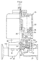
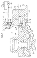
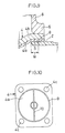
- Fig. 1 is a longitudinally half sectioned front elevation of the preferred embodiment of the diaphragm valve according to the present invention
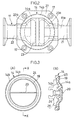
- Fig. 2 is a bottom view thereof.
- the reference numerals 11 denotes a cylindrical valve body.
- an inwardly projecting dam portion 23 serving as a valve seat 13 is provided.
- the reference numeral 12 denotes a diaphragm mounting seat for mounting a peripheral edge portion on a surface side of a diaphragm 14.
- the diaphragm mounting seat 12 is formed on a side wall portion 11a of the valve body 11.
- valve openings 21a and 22a communicated with inlet and outlet pipe portions 21 and 22 formed on opposite sides across the dam portion 23.
- the diaphragm 14 is consisted of a surface side membrane 14a formed of fluorine contained resin and a back surface side membrane 14b formed of rubber stacked on a back surface side of the surface side membrane 14a. Both membranes 14a and 14b are connected by a connecting shaft 24 mounted in the central portion thereof.
- the surface side membrane 14a is formed into a disc shaped configuration of about 1 mm thick of Teflon as fluorine contained resin.
- an annular ridge portion of quadrangular cross section is projected on the peripheral edge portion of the surface.
- an annular projection 19 Adjacent the inner periphery of the annular ridge portion 25, an annular projection 19 is projected.
- a linear projection 20 diametrically connecting the annular projection 19 is projected.
- the back surface side membrane 14b is formed of a synthetic resin strong against temperature variation, into a disc shaped configuration with about 4 mm thick and a slightly greater diameter than that of the surface side membrane 14a.
- a metallic retainer 26 is arranged on the back surface of the back surface side membrane 14b.
- the retainer 26, the back surface side membrane 14b and the surface side membrane 14a are integrally connected via the connecting shaft 24 so as not to cause relative angular displacement with respect to each other.
- annular base 27 connected with a bracket mounting flange 16 on the side of a operating portion 15 by means bolts is projected at a predetermined height.
- annular projection 28 is projected upwardly to define an annular groove 29 adjacent the outer periphery thereof in cooperation with the annular base 27.
- a seat surface of the diaphragm mounting surface 12 is substantially the upper surface of the annular projection 28.
- an annular diaphragm retaining portion 30 is projected from the inner peripheral portion thereof.
- a retaining surface 30a at the lower end of the diaphragm retaining portion 30 is projected downwardly from an abutting surface 16a of the bracket mounting flange 16 for a length ⁇ , as shown in Fig. 4.
- the projecting length ⁇ of the diaphragm retaining portion 30 is set in a length to compress the peripheral portion of the diaphragm 14 to firmly fitting the annular projection 19 onto the annular projection 28 with a constant pressure in the condition where the peripheral portion of the diaphragm 14 having a predetermined thickness is engaged with the diaphragm mounting seat 12 as shown.
- a projecting height of the annular projection 28 from the diaphragm mounting seat 12 a thickness of the diaphragm 14 and a elastic module of the diaphragm 14 are taken into account.
- An engaging groove 32 is formed in the diaphragm retaining portion 30 for receiving an anti-rotation pin 31 projected from a retainer 26.
- the anti-rotation pin 31 serves not only for preventing the diaphragm 14 from rotating but also as positioning means for properly positioning the linear projection 20 projecting from the surface of the surface side membrane 14a on the valve seat 13.
- bolt holes 16a and 27a are formed at four portions, respectively.
- the diaphragm retaining portion 30 may be provided in a form detachable from the bracket mounting flange 16.
- the valve operating portion 15 is formed with an air cylinder connected to a bracket 18 formed with the flange 16 at the lower end.
- the cylinder 15 is constructed with a cylinder body 33, a piston 34 and a piston rod 35 reciprocating in axial direction integrally with the piston 34.
- the piston rod 35 serves as the actuation shaft of the diaphragm valve.
- the lower end piston rod (actuation shaft) 35 is connected to the retainer 26 so that the diaphragm 14 is forms to vary mode between a valve closing mode where the diaphragm 14 is in contact with the valve seat 13 as shown by the solid line of Fig.
- a part of the bracket 18 forms a lower end wall portion 33a of the cylinder body 33.
- the reference numeral 36 denotes a coil spring normally biasing the piston toward valve closing side.
- the diaphragm retaining portion 30 compresses the peripheral portion of the diaphragm 14 over the entire periphery to depress the annular projection 19 of the surface side membrane 14a onto the annular projection 28 of the diaphragm mounting seat 12, and whereby to establish complete seal between the surface side membrane 14a and the annular projection 28 of the mounting seat 12.
- a pressure applied to the peripheral portion of the diaphragm 14 by the diaphragm retaining portion 30 is constant as set by the projecting height of the annular projection 19 from the diaphragm mounting seat 12, the thickness of the diaphragm 14 and the elastic modules of the diaphragm 14.
- the surface side membrane 14a of the diaphragm has the annular ridge portion 25 projected along the peripheral edge portion and the annular projection 19 extending circumferentially at inner side of the annular ridge portion 25.
- the annular ridge portion 25 on the surface side membrane 14a is engaged with the annular groove 29 formed on the outer circumference of the annular projection 28 to abut the annular projection 19 of the surface side membrane 14a onto the annular projection 28 of the diaphragm mounting seat 12.
- the annular ridge portion 24 of the surface side membrane 14a restricts the annular groove 29 formed on the outer circumference of the mounting seat 28 to restrict shrinking of the surface side membrane 14a. Accordingly, as shown in Fig. 4, the annular projection 19 of the surface membrane 14a can be arranged in the vicinity of the inner peripheral edge of the diaphragm mounting seat 12 as close as possible. Thus, a shrinking margin w as a gap between the annular projection 19 of the surface side membrane 14a and the mounting seat 12 can be set as narrow as possible.
- the shrinking margin w is quite narrow as possible, a gap may not be formed between the surface of the surface side membrane 14a and the diaphragm mounting seat. Even when the gap is formed, the gap is shallow to easily accumulate a liquid to facilitate cleaning and is quite sanitary.
- the peripheral edge portion of the diaphragm 14 is not bolted by providing the bolt holes as in the prior art in order to mounting and fixing the diaphragm 14 on the diaphragm mounting seat 12, the diaphragm 14 can be formed into circular shape and whereby to permit saving of the material.
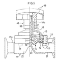
- Fig. 5 shows a diaphragm valve having a manually operable valve operating portion 45.
- the valve operating portion 45 is constructed with a cylindrical threaded portion 18a at the upper end portion of the bracket 18 mounted on the side of the valve body 11, a threaded shaft 38 to meshing engagement with the cylindrical threaded portion 18a and a handle to be operated manually for rotating the threaded shaft 38.
- the threaded shaft 38 serves as the actuation shaft.
- the threaded shaft is shifted back and forth in axial direction to vary the mode of the diaphragm between the valve closing mode abutting onto the valve seat 13 and the valve opening mode released away from the valve seat 13.
- the diaphragm retaining portion uniformly compresses the entire circumference of the peripheral edge portion of the diaphragm to press the peripheral edge portion onto the diaphragm mounting seat.
- a complete seal can be established between the peripheral edge portion on the surface side of the diaphragm and the diaphragm mounting seat.
- the pressure to be exerted on the peripheral edge portion of the diaphragm through the diaphragm retaining portion can be a constant pressure preliminarily set in consideration of the projecting height of the annular projection from the diaphragm mounting seat, the thickness of the diaphragm and the elastic modules of the diaphragm. Therefore, it is only required to fasten the flange onto the annular base by tightening the bolts so as not to cause over tightening or lack of tightening, and not to cause personal error in tightening operation.
- the peripheral edge portion of the diaphragm can be properly fixed on the diaphragm mounting seat over the entire circumference to certainly prevent liquid leakage.
- the diaphragm valve according to the present invention since the diaphragm is provided with the annular ridge portion extending along the peripheral edge portion and the annular projection extending circumferentially at the inner side of the annular ridge portion, and the diaphragm mounting seat is provided with the annular projection.
- the annular projection of the diaphragm is engaged to abut the annular ridge portion of the diaphragm onto the annular projection of the diaphragm mounting seat.
- the annular ridge portion of the surface side membrane restricts the annular groove formed on the outer circumference of the mounting seat to restrict shrinking of the surface side membrane. Accordingly, the annular projection of the surface membrane can be arranged in the vicinity of the inner peripheral edge of the diaphragm mounting seat as close as possible.
- a shrinking margin as a gap between the annular projection of the surface side membrane 14a and the mounting seat can be set as narrow as possible. Since the shrinking margin is quite narrow as possible, a gap may not be formed between the surface of the surface side membrane 14a and the diaphragm mounting seat. Even when the gap is formed, the gap is shallow to easily accumulate a liquid to facilitate cleaning and is quite sanitary.
- the retaining surface of the diaphragm retaining portion can effectively compress the peripheral edge portion of the diaphragm since the diaphragm retaining portion is placed at the position projected for a predetermined length from the abutting surface of the bracket mounting flange abutting onto the annular base.
- the diaphragm can be formed into circular shape material to form the diaphragm can be reduced to achieve material saving.
- valve operating portion when the valve operating portion is formed with the cylinder connected with the bracket mounted on the side of the valve body, driving of the actuation shaft back and force in axial direction can be done automatically. Also, when the valve operating portion is formed with the threaded shaft threadingly engaged with the bracket mounted on the side of the valve body side, and the handle rotatingly operating the threaded shaft, back and forth driving of the actuation shaft in the axial direction can be simply and easily operated manually.
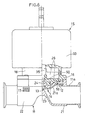
- Figs. 6 and 7 show another embodiment of the diaphragm valve according to the present invention, in which a liquid leakage detection sensor is provided in the diaphragm valve.
- the diaphragm forming the valve body is mounted at a position opposing to the valve seat in the valve body in a manner isolating the surface side contacting with the liquid and the back surface side.
- the diaphragm may seal the surface side and the back surface side having the actuation mechanism with the fastening portion of the peripheral edge portion to constantly contact the liquid only with the surface side.
- valve operation can be performed only by deformation of the diaphragm so as not to require any sliding contact portion, such as a valve shaft portion of various other valves, which easily cause leakage of the liquid.
- it is particularly useful for the field of food industry, pharmaceutical industry and so forth which requires high reliability in safety and sanitary.
- the conventional leakage detection sensor provided in the diaphragm valve it have been known a sensor, in which a conductive rubber layer is provided in the diaphragm for electrically detecting liquid leakage.
- a conductive rubber layer is provided in the diaphragm for electrically detecting liquid leakage.
- the liquid leakage sensor assembly includes a sensor body 50 inserted within an opening portion 60 provided at a predetermined position in the bracket 18, and a detection circuit 51 formed by leading outside of the bracket 18 from the sensor body 50. Also, in the back surface side membrane 4b serving as the back-up membrane of the diaphragm, a leakage announcing conduit 10 is formed.
- the sensor body 50 is constructed with a sealed casing 54 formed with a box-shaped casing body 52 opening in one side surface, an infiltration membrane 53 arranged in the opening surface side of the casing body 52, a strong electrolyte filled in the sealed casing 54, and a pair of electrodes a and b respectively serving as anode and cathode arranged in opposition.
- the infiltration membrane 53 is a membrane arranged inn the opening surface side of he casing body 52 so as to permit penetration of liquid from outside of the sealed casing 54 into the inside but block leakage of the liquid within the casing 54 to the outside.
- the strong electrolyte to be filled within the sealed casing 54 of the sensor body 50 may be NaCl (sodium chloride to be used as a salt or the like) in the preferred embodiment.
- NaCl sodium chloride to be used as a salt or the like
- other material such as NaOH (caustic soda, sodium hydroxide and the like) may also be used.
- the detection circuit 51 is an electric circuit including the electrodes a and b arranged within the sealed casing 54, a power source 55 which is formed with a battery, an ammeter 56 and a lamp 57.
- the casing body 52 Upon mounting of the sensor body 50 onto the opening portion 60 of the bracket 18, the casing body 52 is mounted and fixed via a sealing member 58 in the condition where the infiltration membrane 53 is located at a position contacting with the liquid leaking to he back surface side of the diaphragm 14.
- the liquid leakage detection sensor constructed as set forth above, assuming that the shown diaphragm valve is disposed within the pure water line, if the surface side membrane 14a causes breakage, the water (pure water) leaking to the back surface side through he broken portion of the surface of the surface side membrane 14a penetrates into a gap between the back surface of the surface side membrane 14a and the surface of the back surface side membrane 14b. Then, the leaking liquid flows into the inside of the bracket 18, namely, into the space portion S on the back surface side of the leakage announcing conduit 59 of the back surface side membrane 14b to be accumulated therein, through the leakage announcing conduit 59.
- the leaked water accumulated in the space portion S passes through the infiltration membrane 53 arranged in the sealed casing 54 of the sensor body 50 and then is mixed with NaCl within the sealed casing 54.
- NaCl is dissociated into Na ion (+) and Cl ion (-), namely electrolytically dissociated, for high dielectric constant of the water.
- NaCl is strong electrolyte, it is completely dissociated in the water (no molecule which is not dissociated will be remained).
- the diaphragm 14 is consisted of the thin surface side membrane 14a of fluorine contained resin and the thick back-up membrane 14b of rubber stacked on the back surface side.
- the liquid leakage announcing conduit 59 in the back-up membrane 14b the water leaking through the broken portion of the surface side membrane 14a immediately flows out to the back surface side of the diaphragm 14 through the liquid leakage announcing conduit 59 to contact with the sensor body 50. Therefore, breakage of the surface side membrane 14a can be detected quickly.
- the liquid leakage sensor can detect not only the pure water but also leakage of liquids other than pure water.
- the diaphragm valve of the shown embodiment upon breakage of the diaphragm, the liquid leaking out the backside surface is admixed with the strong electrolyte within the casing through the infiltration membrane of the sensor body to cause electrolytic dissociation of the strong electrolyte to increase electric conductivity of the liquid to detect conductive state of between the electrodes within the casing to detect breakage of the diaphragm. Accordingly, the diaphragm can be used for extended period throughout its life. Particularly, with the liquid leakage sensor, even in case of the liquid having low conductivity, such as pure water, leakage of the liquid due to breakage of the surface side membrane can be certainly detected.
- the diaphragm is formed with the thin surface side membrane of fluorine contained resin and the thick back-up membrane of rubber stacked on the back surface side, and by providing the liquid leakage announcing conduit in the back-up membrane, breakage of the surface side membrane can be detected quickly.
Landscapes
- Engineering & Computer Science (AREA)
- General Engineering & Computer Science (AREA)
- Mechanical Engineering (AREA)
- Fluid-Driven Valves (AREA)
- Details Of Valves (AREA)
- Diaphragms And Bellows (AREA)
Priority Applications (1)
| Application Number | Priority Date | Filing Date | Title |
|---|---|---|---|
| EP20040015521 EP1462693B1 (fr) | 2000-03-31 | 2001-02-26 | Robinet à membrane |
Applications Claiming Priority (4)
| Application Number | Priority Date | Filing Date | Title |
|---|---|---|---|
| JP2000096332 | 2000-03-31 | ||
| JP2000096332A JP4533500B2 (ja) | 2000-03-31 | 2000-03-31 | ダイアフラム弁 |
| JP2000137064 | 2000-05-10 | ||
| JP2000137064A JP4427164B2 (ja) | 2000-05-10 | 2000-05-10 | ダイアフラム弁の漏洩検知センサー |
Related Child Applications (1)
| Application Number | Title | Priority Date | Filing Date |
|---|---|---|---|
| EP20040015521 Division EP1462693B1 (fr) | 2000-03-31 | 2001-02-26 | Robinet à membrane |
Publications (3)
| Publication Number | Publication Date |
|---|---|
| EP1138989A2 true EP1138989A2 (fr) | 2001-10-04 |
| EP1138989A3 EP1138989A3 (fr) | 2003-05-14 |
| EP1138989B1 EP1138989B1 (fr) | 2005-08-17 |
Family
ID=26589028
Family Applications (2)
| Application Number | Title | Priority Date | Filing Date |
|---|---|---|---|
| EP20040015521 Expired - Lifetime EP1462693B1 (fr) | 2000-03-31 | 2001-02-26 | Robinet à membrane |
| EP20010104405 Expired - Lifetime EP1138989B1 (fr) | 2000-03-31 | 2001-02-26 | Robinet à membrane |
Family Applications Before (1)
| Application Number | Title | Priority Date | Filing Date |
|---|---|---|---|
| EP20040015521 Expired - Lifetime EP1462693B1 (fr) | 2000-03-31 | 2001-02-26 | Robinet à membrane |
Country Status (5)
| Country | Link |
|---|---|
| US (1) | US6508266B2 (fr) |
| EP (2) | EP1462693B1 (fr) |
| CN (1) | CN1208567C (fr) |
| DE (2) | DE60133677T2 (fr) |
| HK (1) | HK1039976B (fr) |
Cited By (6)
| Publication number | Priority date | Publication date | Assignee | Title |
|---|---|---|---|---|
| FR2847640A1 (fr) * | 2002-11-27 | 2004-05-28 | Smc Kk | Vannes a deux voies. |
| EP1691116A1 (fr) * | 2005-02-10 | 2006-08-16 | GEMÜ Gebrüder Müller Apparatebau GmbH & Co. KG | Vanne à membrane |
| WO2014015326A1 (fr) * | 2012-07-20 | 2014-01-23 | Itt Manufacturing Enterprises Llc | Joint à bride post-excité à branchement rapide pour robinet à membrane |
| EP2833034A1 (fr) * | 2013-08-02 | 2015-02-04 | Gemü Gebr. Müller Apparatebau Gmbh & Co. Kommanditgesellschaf | Système de membrane pour un dispositif de soupape |
| US9157534B2 (en) | 2012-07-20 | 2015-10-13 | Itt Manufacturing Enterprises Llc. | Two-stud diaphragm for diaphragm valves |
| US9322482B2 (en) | 2012-07-20 | 2016-04-26 | Itt Manufacturing Enterprises Llc. | Temperature compensating flanged joint for a teflon diaphragm valve |
Families Citing this family (43)
| Publication number | Priority date | Publication date | Assignee | Title |
|---|---|---|---|---|
| DE20307457U1 (de) * | 2003-05-13 | 2003-07-31 | GEMÜ Gebr. Müller Apparatebau GmbH & Co. KG, 74653 Ingelfingen | Druckstück für ein Membranventil |
| WO2006052237A1 (fr) * | 2004-11-05 | 2006-05-18 | Petrolvalves Usa | Joint de tige de vanne metallique et systeme d'etancheite |
| EP1726855B1 (fr) * | 2005-05-25 | 2011-04-27 | Big Dutchman (Skandinavien) A/S | Valve pour produits alimentaires avec une sonde de fuite intégrée |
| US7243903B2 (en) * | 2005-06-22 | 2007-07-17 | Wincek Christopher P | Valve diaphragm with a compression restraining ring, and valve including same |
| PL3217051T3 (pl) * | 2006-10-20 | 2020-08-24 | Tyco Fire Products Lp | System ochrony przeciwpożarowej |
| US8235352B2 (en) * | 2007-05-21 | 2012-08-07 | Rain Bird Corporation | Diaphragm valve for irrigation systems |
| GB2460227A (en) * | 2008-05-19 | 2009-11-25 | Walker & Co James Ltd | Valve diaphragm |
| DE102008045857B8 (de) | 2008-09-05 | 2012-02-02 | GEMÜ Gebr. Müller Apparatebau GmbH & Co. KG | Membranventil |
| IL195049A (en) * | 2008-11-02 | 2014-03-31 | Ooval Valves Ltd | A flow smoothing device and method for flow transitions |
| US9250106B2 (en) * | 2009-02-27 | 2016-02-02 | Tandem Diabetes Care, Inc. | Methods and devices for determination of flow reservoir volume |
| EP2459907A1 (fr) * | 2009-07-27 | 2012-06-06 | Merck Sharp & Dohme Corp. | Soupape à diaphragme présentant une étanchéité et une détection des fuites améliorées |
| US8708308B2 (en) * | 2009-08-05 | 2014-04-29 | Itt Manufacturing Enterprises, Inc. | Sealing arrangement for a diaphragm valve |
| CA2790970A1 (fr) * | 2010-03-04 | 2011-09-09 | Denis Saint-Paul | Obturateur a diaphragme |
| JP5249310B2 (ja) | 2010-12-17 | 2013-07-31 | Ckd株式会社 | 流体制御弁 |
| JP5802532B2 (ja) * | 2011-12-05 | 2015-10-28 | 株式会社フジキン | ダイヤフラム弁およびダイヤフラム弁用シートホルダユニット |
| JP5435439B2 (ja) * | 2012-06-22 | 2014-03-05 | Smc株式会社 | 二方弁 |
| CN103527812A (zh) * | 2012-07-05 | 2014-01-22 | 上海阀门五厂有限公司 | 一种核级m型气动直通隔膜阀 |
| DE102012222062B3 (de) * | 2012-12-03 | 2014-04-10 | GEMÜ Gebr. Müller Apparatebau GmbH & Co. KG | Membranventil |
| JP6232224B2 (ja) * | 2013-07-26 | 2017-11-15 | 株式会社フジキン | ダイヤフラム弁 |
| CN104514912B (zh) * | 2013-09-29 | 2017-06-06 | 厦门三登塑胶工业有限公司 | 气动马达隔膜阀 |
| JP5891536B2 (ja) * | 2013-11-11 | 2016-03-23 | Smc株式会社 | 弁装置 |
| US9366346B2 (en) * | 2014-02-28 | 2016-06-14 | Itt Manufacturing Enterprises Llc. | Valve having at least one hourglass studs for coupling to diaphragm and compressor/spindle components |
| CN103953747A (zh) * | 2014-05-21 | 2014-07-30 | 江苏宏博机械制造有限公司 | 一种氯碱专用气动隔膜阀 |
| US10041604B2 (en) * | 2014-10-20 | 2018-08-07 | Aktiebolaget Skf | Valve operator assembly and valve equipped with such assembly |
| DE102014221863B4 (de) | 2014-10-27 | 2018-02-15 | Festo Ag & Co. Kg | Membranventil |
| EP3133326B1 (fr) * | 2015-08-18 | 2021-12-15 | Danfoss A/S | Vanne |
| JP6654060B2 (ja) * | 2016-02-18 | 2020-02-26 | Ckd株式会社 | ダイヤフラム弁 |
| CN106195323A (zh) * | 2016-07-12 | 2016-12-07 | 浙江鼎耐塑胶管阀有限公司 | 一种气动活塞式隔膜阀 |
| CN108662191A (zh) * | 2017-03-30 | 2018-10-16 | 苏州巴恩斯通环保科技有限公司 | 一种隔膜阀门 |
| CN111757998B (zh) * | 2018-03-19 | 2022-05-27 | 日立金属株式会社 | 隔膜阀以及使用该隔膜阀的质量流量控制装置 |
| JP7262280B2 (ja) * | 2018-04-10 | 2023-04-21 | 旭有機材株式会社 | ダイヤフラムバルブ |
| US11927280B2 (en) * | 2018-06-30 | 2024-03-12 | Fujikin Incorporated | Diaphragm valve and monitoring method thereof with improved leak detection |
| WO2021144060A1 (fr) * | 2020-01-14 | 2021-07-22 | Gemü Gebr. Müller Apparatebau Gmbh & Co. Kommanditgesellschaft | Diaphragme et soupape à diaphragme |
| DE102020120641A1 (de) | 2020-08-05 | 2022-02-10 | Gemü Gebr. Müller Apparatebau Gmbh & Co. Kommanditgesellschaft | Vorrichtung zur Verbindung eines Ventilantriebs mit einer Ventilmembran |
| CN117480335A (zh) | 2021-04-16 | 2024-01-30 | 道格拉斯·亚瑟·纽伯格 | 阀门致动器组件 |
| CN113175556A (zh) * | 2021-06-16 | 2021-07-27 | 福建比力安科技有限公司 | 一种气体或液体用的开关控制阀 |
| JP7128379B1 (ja) * | 2022-05-16 | 2022-08-30 | 日本ダイヤバルブ株式会社 | ダイヤフラム及びダイヤフラム弁 |
| EP4605675A2 (fr) * | 2022-10-19 | 2025-08-27 | Newberg, Douglas, Arthur | Ensemble d'actionneurs de valves et leurs procédés |
| CN116105937B (zh) * | 2023-02-15 | 2024-04-30 | 东台市鑫航船用配件有限公司 | 一种用于阀体加工生产线的检测装置 |
| DE102023108043A1 (de) * | 2023-03-29 | 2024-10-02 | Bürkert Werke GmbH & Co. KG | Antriebsbaugruppe für ein Membranventil und Membranventil |
| FR3151890B1 (fr) * | 2023-08-03 | 2025-09-05 | Exel Ind | Vanne et appareil à fluide pressurisé |
| EP4589181A1 (fr) * | 2024-01-18 | 2025-07-23 | Georg Fischer Rohrleitungssysteme AG | Joint d'étanchéité pour soupape à membrane |
| DE102024117393A1 (de) * | 2024-06-20 | 2025-12-24 | Gemü Gebr. Müller Apparatebau Gmbh & Co. Kommanditgesellschaft | Membranventil, Ventilmembran und Membranlage mit Trennabschnitt |
Family Cites Families (16)
| Publication number | Priority date | Publication date | Assignee | Title |
|---|---|---|---|---|
| US2988322A (en) * | 1955-01-25 | 1961-06-13 | Hills Mccanna Co | Diaphragm valve |
| US3154286A (en) * | 1960-11-03 | 1964-10-27 | Hills Mccanna Co | Weir valve |
| US3631882A (en) * | 1970-01-29 | 1972-01-04 | Grinnell Corp | Diaphragm valve |
| FR2287633A1 (fr) * | 1974-10-08 | 1976-05-07 | Muguet Fernand | Vanne a membrane |
| FR2373734A1 (fr) * | 1976-12-07 | 1978-07-07 | Klein Schanzlin & Becker Ag | Soupape a membrane |
| DE3123028C2 (de) * | 1981-06-10 | 1986-02-20 | Johannes Erhard, H. Waldenmaier Erben Süddeutsche Armaturenfabrik GmbH & Co, 7920 Heidenheim | Membranventil |
| US5214387A (en) * | 1989-03-06 | 1993-05-25 | Fenner Richard D | Electrolytic resistivity leak detector |
| US4901751A (en) * | 1989-06-15 | 1990-02-20 | Systems Chemistry, Inc. | Fluid control valve and system with leak detection and containment |
| US5261442A (en) * | 1992-11-04 | 1993-11-16 | Bunnell Plastics, Inc. | Diaphragm valve with leak detection |
| US5316035A (en) * | 1993-02-19 | 1994-05-31 | Fluoroware, Inc. | Capacitive proximity monitoring device for corrosive atmosphere environment |
| US5517181A (en) * | 1993-06-08 | 1996-05-14 | The United States Of America As Represented By The United Staes Department Of Energy | Hazardous fluid leak detector |
| FR2740873B1 (fr) * | 1995-11-07 | 1998-01-02 | D Auria Stanislas Boulet | Dispositif de detection de presence de liquide |
| EP1020779B1 (fr) * | 1996-08-21 | 2007-10-17 | Fisher Controls International LLC | Vanne comprenant un élément en élastomère |
| JPH10169802A (ja) * | 1996-12-13 | 1998-06-26 | Smc Corp | 流体圧制御用ダイヤフラム |
| US6000416A (en) * | 1997-06-04 | 1999-12-14 | Furon Company | Compact valve with rolling diaphragm poppet |
| US6175310B1 (en) * | 1999-05-10 | 2001-01-16 | Richard J. Gott | Leak detection tape |
-
2001
- 2001-02-20 US US09/788,839 patent/US6508266B2/en not_active Expired - Lifetime
- 2001-02-26 EP EP20040015521 patent/EP1462693B1/fr not_active Expired - Lifetime
- 2001-02-26 DE DE2001633677 patent/DE60133677T2/de not_active Expired - Lifetime
- 2001-02-26 DE DE2001612639 patent/DE60112639T2/de not_active Expired - Lifetime
- 2001-02-26 EP EP20010104405 patent/EP1138989B1/fr not_active Expired - Lifetime
- 2001-03-30 CN CNB011121963A patent/CN1208567C/zh not_active Expired - Fee Related
-
2002
- 2002-02-20 HK HK02101226.2A patent/HK1039976B/zh not_active IP Right Cessation
Non-Patent Citations (1)
| Title |
|---|
| None |
Cited By (10)
| Publication number | Priority date | Publication date | Assignee | Title |
|---|---|---|---|---|
| FR2847640A1 (fr) * | 2002-11-27 | 2004-05-28 | Smc Kk | Vannes a deux voies. |
| US6948517B2 (en) | 2002-11-27 | 2005-09-27 | Smc Kabushiki Kaisha | Two-way valve |
| EP1691116A1 (fr) * | 2005-02-10 | 2006-08-16 | GEMÜ Gebrüder Müller Apparatebau GmbH & Co. KG | Vanne à membrane |
| US7717127B2 (en) | 2005-02-10 | 2010-05-18 | Gemü Gebrüder Müller Apparatebau GmbH & Co. KG | Diaphragm valve |
| WO2014015326A1 (fr) * | 2012-07-20 | 2014-01-23 | Itt Manufacturing Enterprises Llc | Joint à bride post-excité à branchement rapide pour robinet à membrane |
| US9016307B2 (en) | 2012-07-20 | 2015-04-28 | Itt Manufacturing Enterprises Llc. | Quick connect, post energized flanged joint for a diaphragm valve |
| US9157534B2 (en) | 2012-07-20 | 2015-10-13 | Itt Manufacturing Enterprises Llc. | Two-stud diaphragm for diaphragm valves |
| US9322482B2 (en) | 2012-07-20 | 2016-04-26 | Itt Manufacturing Enterprises Llc. | Temperature compensating flanged joint for a teflon diaphragm valve |
| EP2875266B1 (fr) | 2012-07-20 | 2016-09-14 | ITT Manufacturing Enterprises LLC | Joint à bride post-excité à branchement rapide pour robinet à membrane |
| EP2833034A1 (fr) * | 2013-08-02 | 2015-02-04 | Gemü Gebr. Müller Apparatebau Gmbh & Co. Kommanditgesellschaf | Système de membrane pour un dispositif de soupape |
Also Published As
| Publication number | Publication date |
|---|---|
| US6508266B2 (en) | 2003-01-21 |
| DE60133677D1 (de) | 2008-05-29 |
| US20010025654A1 (en) | 2001-10-04 |
| EP1462693A1 (fr) | 2004-09-29 |
| DE60112639T2 (de) | 2006-05-18 |
| EP1462693B1 (fr) | 2008-04-16 |
| CN1208567C (zh) | 2005-06-29 |
| CN1319735A (zh) | 2001-10-31 |
| DE60112639D1 (de) | 2005-09-22 |
| HK1039976B (zh) | 2005-10-14 |
| HK1039976A1 (en) | 2002-05-17 |
| DE60133677T2 (de) | 2009-04-30 |
| EP1138989A3 (fr) | 2003-05-14 |
| EP1138989B1 (fr) | 2005-08-17 |
Similar Documents
| Publication | Publication Date | Title |
|---|---|---|
| EP1138989B1 (fr) | Robinet à membrane | |
| US4971523A (en) | Dual diaphragm apparatus with diaphragm assembly and rupture detection methods | |
| JP4180832B2 (ja) | メカニカルシール装置 | |
| EP1091156A2 (fr) | Améliorations concernant les joints étanches aux fluides | |
| JP4632162B2 (ja) | 流体機器の流体通路取り出し口の構造 | |
| JPH0252756B2 (fr) | ||
| JP2000352468A (ja) | 自動弁 | |
| JP4268913B2 (ja) | 流体機器どうしの接続構造 | |
| JP2003343753A (ja) | バルブ | |
| JP4744319B2 (ja) | ダイヤフラム弁 | |
| JP4533500B2 (ja) | ダイアフラム弁 | |
| JP4427164B2 (ja) | ダイアフラム弁の漏洩検知センサー | |
| KR20080111294A (ko) | 다이어프램 및 그 제조 방법 그리고 그것을 갖는다이어프램 밸브 | |
| JP3607690B2 (ja) | バルブ | |
| CN106062439B (zh) | 隔膜的固定构造、具备其的隔膜泵和阀装置、以及隔膜的固定方法 | |
| JP4651358B2 (ja) | ダイヤフラム弁 | |
| CN111256919B (zh) | 一种自动识别产品装夹的自动线气密性检测夹具 | |
| JP4268914B2 (ja) | 流体機器どうしの接続構造 | |
| CN223881531U (zh) | 一种紧固件、铆接组件、焊铆组件和焊铆模具 | |
| JPS6360238B2 (fr) | ||
| JP2009236277A (ja) | ダイヤフラム式バルブ装置 | |
| JPH10185052A (ja) | 高圧配管用継手構造 | |
| JP2003269628A (ja) | ピンチバルブ | |
| JP2000205412A (ja) | 弁箱のシ―ル構造 | |
| JPH1194104A (ja) | 逆止弁用カートリッジ |
Legal Events
| Date | Code | Title | Description |
|---|---|---|---|
| PUAI | Public reference made under article 153(3) epc to a published international application that has entered the european phase |
Free format text: ORIGINAL CODE: 0009012 |
|
| AK | Designated contracting states |
Kind code of ref document: A2 Designated state(s): AT BE CH CY DE DK ES FI FR GB GR IE IT LI LU MC NL PT SE TR |
|
| AX | Request for extension of the european patent |
Free format text: AL;LT;LV;MK;RO;SI |
|
| PUAL | Search report despatched |
Free format text: ORIGINAL CODE: 0009013 |
|
| AK | Designated contracting states |
Designated state(s): AT BE CH CY DE DK ES FI FR GB GR IE IT LI LU MC NL PT SE TR |
|
| AX | Request for extension of the european patent |
Extension state: AL LT LV MK RO SI |
|
| RIC1 | Information provided on ipc code assigned before grant |
Ipc: 7G 01M 3/04 B Ipc: 7G 01M 3/18 B Ipc: 7F 16K 31/122 B Ipc: 7F 16K 7/12 A |
|
| 17P | Request for examination filed |
Effective date: 20031001 |
|
| AKX | Designation fees paid |
Designated state(s): DE |
|
| 17Q | First examination report despatched |
Effective date: 20040224 |
|
| GRAP | Despatch of communication of intention to grant a patent |
Free format text: ORIGINAL CODE: EPIDOSNIGR1 |
|
| GRAS | Grant fee paid |
Free format text: ORIGINAL CODE: EPIDOSNIGR3 |
|
| GRAA | (expected) grant |
Free format text: ORIGINAL CODE: 0009210 |
|
| AK | Designated contracting states |
Kind code of ref document: B1 Designated state(s): DE |
|
| REF | Corresponds to: |
Ref document number: 60112639 Country of ref document: DE Date of ref document: 20050922 Kind code of ref document: P |
|
| PLBE | No opposition filed within time limit |
Free format text: ORIGINAL CODE: 0009261 |
|
| STAA | Information on the status of an ep patent application or granted ep patent |
Free format text: STATUS: NO OPPOSITION FILED WITHIN TIME LIMIT |
|
| 26N | No opposition filed |
Effective date: 20060518 |
|
| PGFP | Annual fee paid to national office [announced via postgrant information from national office to epo] |
Ref country code: DE Payment date: 20130220 Year of fee payment: 13 |
|
| REG | Reference to a national code |
Ref country code: DE Ref legal event code: R119 Ref document number: 60112639 Country of ref document: DE |
|
| REG | Reference to a national code |
Ref country code: DE Ref legal event code: R119 Ref document number: 60112639 Country of ref document: DE Effective date: 20140902 |
|
| PG25 | Lapsed in a contracting state [announced via postgrant information from national office to epo] |
Ref country code: DE Free format text: LAPSE BECAUSE OF NON-PAYMENT OF DUE FEES Effective date: 20140902 |