EP1139366A2 - Mehrkontakt-Eingabegerät - Google Patents
Mehrkontakt-Eingabegerät Download PDFInfo
- Publication number
- EP1139366A2 EP1139366A2 EP00121846A EP00121846A EP1139366A2 EP 1139366 A2 EP1139366 A2 EP 1139366A2 EP 00121846 A EP00121846 A EP 00121846A EP 00121846 A EP00121846 A EP 00121846A EP 1139366 A2 EP1139366 A2 EP 1139366A2
- Authority
- EP
- European Patent Office
- Prior art keywords
- side switches
- movable electrode
- center switch
- movable
- electrode
- Prior art date
- Legal status (The legal status is an assumption and is not a legal conclusion. Google has not performed a legal analysis and makes no representation as to the accuracy of the status listed.)
- Granted
Links
Images


Classifications
-
- H—ELECTRICITY
- H01—ELECTRIC ELEMENTS
- H01H—ELECTRIC SWITCHES; RELAYS; SELECTORS; EMERGENCY PROTECTIVE DEVICES
- H01H13/00—Switches having rectilinearly-movable operating part or parts adapted for pushing or pulling in one direction only, e.g. push-button switch
- H01H13/70—Switches having rectilinearly-movable operating part or parts adapted for pushing or pulling in one direction only, e.g. push-button switch having a plurality of operating members associated with different sets of contacts, e.g. keyboard
- H01H13/76—Switches having rectilinearly-movable operating part or parts adapted for pushing or pulling in one direction only, e.g. push-button switch having a plurality of operating members associated with different sets of contacts, e.g. keyboard wherein some or all of the operating members actuate different combinations of the contact sets, e.g. ten operating members actuating different combinations of four contact sets
-
- G—PHYSICS
- G05—CONTROLLING; REGULATING
- G05G—CONTROL DEVICES OR SYSTEMS INSOFAR AS CHARACTERISED BY MECHANICAL FEATURES ONLY
- G05G9/00—Manually-actuated control mechanisms provided with one single controlling member co-operating with two or more controlled members, e.g. selectively, simultaneously
- G05G9/02—Manually-actuated control mechanisms provided with one single controlling member co-operating with two or more controlled members, e.g. selectively, simultaneously the controlling member being movable in different independent ways, movement in each individual way actuating one controlled member only
- G05G9/04—Manually-actuated control mechanisms provided with one single controlling member co-operating with two or more controlled members, e.g. selectively, simultaneously the controlling member being movable in different independent ways, movement in each individual way actuating one controlled member only in which movement in two or more ways can occur simultaneously
- G05G9/047—Manually-actuated control mechanisms provided with one single controlling member co-operating with two or more controlled members, e.g. selectively, simultaneously the controlling member being movable in different independent ways, movement in each individual way actuating one controlled member only in which movement in two or more ways can occur simultaneously the controlling member being movable by hand about orthogonal axes, e.g. joysticks
- G05G2009/04777—Manually-actuated control mechanisms provided with one single controlling member co-operating with two or more controlled members, e.g. selectively, simultaneously the controlling member being movable in different independent ways, movement in each individual way actuating one controlled member only in which movement in two or more ways can occur simultaneously the controlling member being movable by hand about orthogonal axes, e.g. joysticks with additional push or pull action on the handle
-
- H—ELECTRICITY
- H01—ELECTRIC ELEMENTS
- H01H—ELECTRIC SWITCHES; RELAYS; SELECTORS; EMERGENCY PROTECTIVE DEVICES
- H01H2205/00—Movable contacts
- H01H2205/016—Separate bridge contact
- H01H2205/024—Means to facilitate positioning
- H01H2205/028—Protuberances on substrate
Definitions
- the present invention relates to a multi-contact inputting device, and more particularly to a multi-contact inputting device which has a center switch and plural side switches that are placed around the center switch, and in which the center switch and the side switches are individually opened and closed by operating an operation member.
- a multi-contact inputting device is used for inputting and outputting different signals by operating one or plural operation members.
- a device is employed in which each of the center switch and the side switches is formed by combining a stationary electrode, and movable electrodes each configured by a snap plate covering the stationary electrode.
- spaces for respectively accommodating the movable electrodes each configured by a snap plate are formed by partitioning the body so as not to overlap with each other.
- the body in which the center switch and the side switches are placed must be formed into a size which allows the movable electrodes each configured by a snap plate to be placed so as not to overlap with each other in the thickness direction of the body. Consequently, there arises a situation in which the size of the body is determined by the size and the number of the snap plates forming the movable electrodes.
- the concept that the movable electrodes each configured by a snap plate are placed so as not to overlap with each other in the thickness direction of the body constitutes one of obstacles to reduce the size of the body so as to attain miniaturization and compaction of the whole shape of a multi-contact inputting device.
- the present invention has been conducted in view of the above-mentioned circumstances under the concept that, unlike the conventional art, movable electrodes constituting a center switch and plural side switches and each configured by a snap plate are placed so as to overlap with each other in the thickness direction of the body.
- the multi-contact inputting device has a center switch S1, and plural side switches S2 which are placed around the center switch S1.
- Each of the center switch S1 and the plural side switches S2 is formed by: a stationary electrode 31 or 32 disposed in a body 1; and a stationary electrode 41 or 42 configured by a snap plate which is placed so as to be separable from and contactable with the stationary electrode 31 or 32, and to cover the stationary electrode 31 or 32.
- the device further comprises an operation member 7 which can individually open and close the center switch S1 and the side switches S2.
- a plurality of such operation members may be provided for each of the center switch and the side switches. Alternatively, a single operation member which can individually operate the center switch and the plural side switches may be provided.
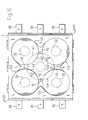
- the plural side switches S2 are placed so that a part of the movable electrode 42 of each of the side switches overlaps with the movable electrode 41 of the center switch S1 in a thickness direction of the body 1.
- the spaces for respectively accommodating the movable electrodes 41 and 42 can be narrowed by a length corresponding to the overlapping width D of the electrodes, as compared with a configuration such as that of the conventional multi-contact inputting device described in the beginning, in which the movable electrode of the center switch and the movable electrodes of the plural side switches are placed so as not to overlap with each other in the thickness direction of the body.
- the movable electrode of the center switch S1 may be placed so as to overlap above the movable electrodes of the plural side switches S2, or alternatively the movable electrodes of the plural side switches S2 may be placed so as to overlap above the movable electrode of the center switch S1.
- positioning means for positioning the movable electrode 41 of the center switch S1 and the movable electrodes 42 of the side switches S2 are suitably defined, and hence a situation in which any one of the movable electrodes 41 and 42 is positionally deviated to impair the operation reliability does not occur.
- a recess 22 into which the movable electrode 41 of the center switch S1 is to be fitted, and recesses 21 into which the movable electrodes 42 of the side switches S2 are to be respectively fitted are disposed in the body 1, and the positioning means is formed by the recesses 22 and 21.
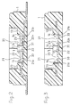
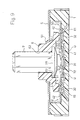
- the movable electrode 41 of the center switch S1 and the movable electrodes 42 of the side switches S2 have an arcuate section shape which upward swells, an outer peripheral edge of the movable electrode 41 of the center switch S1 is seated on a bottom face of the recess 22 for positioning the movable electrode 41 of the center switch S1, outer peripheral edges of the movable electrodes 42 of the side switches S2 are seated on bottom faces of the recesses 21 for positioning the movable electrode 42 of the side switches S2, respectively, and steps H are formed between the bottom face of the recess 22 for positioning the movable electrode 41 of the center switch S1 and the bottom faces of the recesses 21 for positioning the movable electrode 42 of the side switches S2, respectively.
- the outer peripheral edge of the movable electrode 41 of the center switch S1 is placed with being separated in the thickness direction of the body from the outer peripheral edges of the movable electrodes 42 of the side switches S2. Therefore, the outer peripheral edge of the movable electrode 41 of the center switch S1, and the outer peripheral edges of the movable electrodes 42 of the side switches S2 can be placed so as to overlap with each other in the thickness direction of the body 1.
- a common terminal 33 is placed on the bottom face of the recess 22 into which the movable electrode 41 of the center switch S1 is to be fitted, and the bottom faces of the recesses 21 into which the movable electrode 42 of the movable electrode 42 are to be fitted, respectively, so as to be electrically connected to each other, and the outer peripheral edge of the movable electrode 41 of the center switch S1 and the outer peripheral edges of the movable electrodes 42 of the side switches S2 are in contact with the common terminal 33.
- this configuration there arises no obstacle even when the movable electrode 41 of the center switch S1 and the movable electrodes 42 of the side switches S2 which are placed so as to overlap with each other are in contact with each other to be electrically connected.
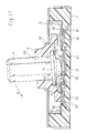
- gaps U are formed between an upper face of the movable electrode 41 of the center switch S1 and the outer peripheral edges of the movable electrodes 42 of the side switches S2, respectively, each of the gaps having an area which can absorb displacement of the outer peripheral edge of the movable electrode 42 of corresponding one of the side switches S2 due to flexural deformation that is caused when the movable electrode 42 is pressed down by the operation member 7. According to this configuration, even when the movable electrode 42 of the side switch S2 is operated via the operation member 7 to be flexurally deformed, a situation in which the movable electrode 42 of the side switch S2 interferes with the movable electrode 41 of the center switch S1 to damage the movable electrodes 41 and 42 does not occur.
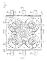
- the side switches S2 are placed in four positions at regular angular intervals around the single center switch S1, respectively, the movable electrode 41 of the center switch S1 and the movable electrodes 42 of the side switches S2 are configured by dome-like snap plates which have a circular shape in a plan view, and which have the same shape and size, respectively, the recesses 21 for positioning the movable electrodes 42 of the side switches S2 are separated from one another by four partition walls 13 which form the recesses 21, and a recess surrounded by inner end faces 14 of the partition walls 13 is formed as the recess 22 for positioning the movable electrode 41 of the center switch S1.
- the one center switch S1 and the four side switches S2 are selectively used so that plural kinds (for example, five kinds) of signals can be input and output.
- a body 1 is configured by a flat synthetic resin molded piece which has a substantially square shape in a plan view.
- the body 1 comprises a peripheral wall 12 which forms the outer peripheral edge of the body 1.
- the body 1 further comprises four partition walls 13 which inward protrude from four positions of the peripheral wall 12 and arranged at regular angular intervals, respectively.
- Four recesses 21 which are located at regular angular intervals are formed by the inner face of the peripheral wall 12, and the both side faces of the four partition walls 13.
- a single center recess 22 is formed in a portion surrounded by the inner end faces 14 of the four partition walls 13.
- each of the four recesses 21 separated by the four partition walls 13 is a circular recess in which the inner face is formed as an arcuate face. Furthermore, the inner end faces 14 of the partition walls 13 forming the single center recess 22 are formed as arcuate faces the center of which coincide with one another. Therefore, also the recess 22 is a circular recess.
- the single center recess 22 communicates with the four surrounding recesses 21 through spaces between adjacent ones of the partition walls 13.
- steps H shown in Fig. 5 are formed in boundary portions 23 between the substantially square region including the whole of the center recess 22 and the regions outsides the square region, respectively. Across each of the boundary portions 23, the substantially square region including the whole of the center recess 22 is stepwise lower than the outer region. According to this configuration, bottom faces 21a of the four surrounding recesses 21 are located at a level which is higher by one step than a bottom face 22a of the center recess 22.
- a stationary electrode 31 is placed on the bottom face 22a of the single center recess 22.
- the face of the stationary electrode 31 is flush with the bottom face 22a of the center recess 22.
- Stationary electrodes 32 are placed on the bottom faces 21a of the four surrounding recesses 21 which are located at a higher level than the bottom face 22a of the center recess 22, respectively.
- the faces of the stationary electrodes 32 are flush with the bottom faces 21a of the recesses 21.
- a common terminal 33 which is formed by a single metal plate is placed with being electrically insulated from the stationary electrodes 31 and 32.
- the upper face of the common terminal 33 is flush with the bottom faces 21a and 22a.
- soldering terminal 34 is formed continuously with the stationary electrode 31 which is placed in the center recess 22.
- Soldering terminals 35 are formed continuously with the stationary electrodes 32 which are placed in the four surrounding recesses 21, respectively.
- a soldering terminal 36 is formed continuously with the common terminal 33.
- sets each configured by three soldering terminals are distributed to the right and left sides of the body 1, respectively, and laterally protrude therefrom.
- the soldering terminals 34, 35, and 36 are of the surface mount type.
- the soldering terminals 34, 35, and 36 may be formed as those of the pin type.
- the center recess 22 and the four surrounding recesses 21 have the same diameter.
- movable electrodes 41 and 42 respectively configured by dome-like snap plates which have a circular shape in a plan view, and which have the same shape and size are fitted into the recesses 21 and 22, respectively.
- Outer peripheral edges of the movable electrodes 41 and 42 are seated on the bottom faces 22a and 21a of the recesses 22 and 21 under the condition that the movable electrodes are in contact with the common terminal 33.
- the movable electrode 41 which is fitted into the center recess 22 is formed by stacking two snap plates of the same size and shape.
- the movable electrodes 41 and 42 are slightly smaller in diameter than the recesses 22 and 21.
- the movable electrode 41 which is fitted into the center recess 22 can be flexurally deformed in the center recess 22 with accompanying a snap operation
- the movable electrodes 42 which are fitted into the four surrounding recesses 21 can be flexurally deformed in the recesses 21 with accompanying a snap operation, respectively.
- a part of each of the movable electrodes 42 which are fitted into the four surrounding recesses 21 is placed so as to, in the thickness direction of the body 1, overlap with respective one of four portions of the outer periphery of the movable electrode 41 which is fitted into the center recess 22.
- the stationary electrode 31 on the bottom face 22a of the center recess 22, and the movable electrode 41 which is fitted into the recess 22 so as to cover the stationary electrode constitute the center switch S1.
- the stationary electrodes 32 on the bottom faces 21a of the four surrounding recesses 21, and the movable electrodes 42 which are respectively fitted into the recesses 21 so as to cover the stationary electrodes 32 constitute the four side switches S2.
- the movable electrodes 42 of the four side switches S2 surrounding the center switch are placed so as to partly overlap in the thickness direction of the body 1.
- the center switch S1 is placed in the center of the body 1 and the four side switches S2 are placed with being distributed with respect to the center switch S1 in diagonal directions of the body 1 as shown in, for example, Fig.
- the diagonal length of the body 1 can be shortened by a length corresponding to the overlapping widths D between the movable electrode 41 of the center switch S1 and the movable electrodes 42 of the two side switches S2 which are placed in a diagonal direction of the body, as compared with the case where the movable electrode 41 are placed so as not overlap with two the movable electrodes 42.
- Each of the movable electrodes 41 and 42 of the center switch S1 and the four side switches S2 is individually positioned by the respective one of the recesses 22 and 21 so as not to be positionally deviated. Consequently, the operation reliability of the opening and closing operations of the center switch S1 and the side switches S2 can be maintained to be excellent.
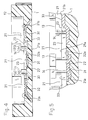
- the body 1 is covered with a cover 5 made of a metal.
- a guide ridge 51 having a ring like shape in which the diameter is gradually reduced as moving upward is disposed in the center of the cover 5.
- a movable member 6 is held by the movable electrodes 42 and the cover 5 via the guide ridge 51 so as to be swingable in every direction.
- Pressing portions 61 which respectively correspond to the movable electrodes 42 of the four side switches S2 are disposed on the rear face of the movable member.
- An operation member 7 is passed through a center hole 62 of the movable member 6 so as to be axially slidable.
- a flange 71 which is formed integrally with a lower end portion of the operation member 7 is opposed to the lower face 63 of the movable member 6.
- a pressing portion 72 corresponding to the movable electrode 41 of the center switch S1 is disposed on the lower face of the flange 71.
- the operation member 7 when an external force such as that in a swinging direction or in the pressing direction is not applied to the operation member 7, the pressing portion 72 of the operation member 7 is supported by the movable electrode 41 of the center switch S1 as shown in Fig. 9, and the four pressing portions 61 of the movable member 6 are supported by the movable electrodes 42 of the four side switches S2, respectively. Therefore, the operation member 7 maintains a neutral posture in which the member stands upright.
- the operation member 7 When the closed or opened state of the center switch S1 is to be switched over, the operation member 7 is pressed down as indicated by the arrow a of Fig. 10. As a result, the operation member 7 is lowered with respect to the movable member 6, and the pressing portion 72 of the operation member 7 presses down the movable electrode 41 of the center switch S1 to cause the electrode to be flexurally deformed while performing a snap operation. As shown in the figure, therefore, the movable electrode 41 makes contact with the stationary electrode 31 to attain electrical conduction between the electrodes 41 and 31, whereby the closed or opened state of the center switch S1 is switched over.
- the operation member 7 When the closed or opened state of the predetermined one of the side switches S2 is to be switched over, the operation member 7 is swung toward the side switch S2 as indicated by the arrow b of Fig. 11. As a result, the movable member 6 is pushed by the operation member 7 to be tilted, and the predetermined one of the pressing portions 61 of the movable member 6 presses down the movable electrode 42 of the predetermined side switch S2 to cause the electrode to be flexurally deformed while performing a snap operation. As shown in the figure, therefore, the movable electrode 42 makes contact with the stationary electrode 32 to attain electrical conduction between the electrodes 42 and 32, whereby the closed or opened state of the side switch S2 is switched over. When the closed or opened state of another one of the side switches S2 is to be switched over, similar operations are performed.
- the operation member 7 is axially slidable with respect to the movable member 6. Therefore, the operation of pressing down the operation member 7 to switch over the closed or opened state of the center switch S1, and that of tilting the movable member 6 together with the operation member 7 to switch over the closed or opened state of the predetermined one of the side switches S2 can be simultaneously performed.
- the closed or opened states of the center switch S1 and the four side switches S2 can be independently switched over by pressing or tilting the single operation member 7.
- operation members may be respectively disposed for the center switch S1 and the four side switches S2, and the closed or opened states of the center switch S1 and the four side switches S2 can be independently switched over by independently operating the operation members.
- Each of the movable electrodes 41 and 42 of the center switch S1 and the side switches S2 is formed by the circular dome-like snap plate which upward swells.
- the movable electrodes may be formed by snap plates of another shape (for example, rectangular) and having an arcuate section shape which upward swells.
- the common terminal 33 is formed as a common terminal which is in contact with both the movable electrode 41 of the center switch S1 and the movable electrode 42 of the corresponding one of the four side switches S2. Even when the overlapping portions of the movable electrodes 41 and 42 of the switches S1 and S2 are in contact with each other, therefore, there arises no problem in the opening and closing operations of the switches. When the overlapping portions of the movable electrodes 41 and 42 are in contact with each other, however, there is a fear that the movable electrodes 41 and 42 may be damaged because, when the movable electrode 42 of one of the side switches S2 is flexurally deformed, for example, the movable electrode 42 rubs against the movable electrode 41 of the center switch S1.
- gaps U between the upper face of the movable electrode 41 of the center switch S1 and the outer peripheral edges of the movable electrodes 42 of the side switches S2, respectively.
- it desirable to form the gaps U so that, when each of the movable electrodes 42 of the side switches S2 is pressed by the operation member 7 or the movable member 6 to be flexurally deformed, displacement of the outer peripheral edge of the movable electrode 42 is absorbed by the corresponding one of the gaps U.
- the steps H are formed between the bottom face 22a of the center recess 22 into which the movable electrode 41 of the center switch S1 is fitted, and the bottom faces 21a of the recesses 21 into which the movable electrodes 42 of the side switches S2 are fitted, so that the movable electrodes 41 and 42 are placed in an overlapping manner.
- the movable electrodes 41 and 42 may be positioned by using fixation means including an adhesive tape or the like so as to be placed in an overlapping manner.
- the movable electrodes 42 of the side switches S2 are individually formed. Alternatively, two or all of the electrodes may be formed as an integral member.
Landscapes
- Physics & Mathematics (AREA)
- General Physics & Mathematics (AREA)
- Engineering & Computer Science (AREA)
- Automation & Control Theory (AREA)
- Switches With Compound Operations (AREA)
- Push-Button Switches (AREA)
Applications Claiming Priority (2)
| Application Number | Priority Date | Filing Date | Title |
|---|---|---|---|
| JP2000092065 | 2000-03-29 | ||
| JP2000092065A JP2001283690A (ja) | 2000-03-29 | 2000-03-29 | 多接点入力装置 |
Publications (3)
| Publication Number | Publication Date |
|---|---|
| EP1139366A2 true EP1139366A2 (de) | 2001-10-04 |
| EP1139366A3 EP1139366A3 (de) | 2003-05-28 |
| EP1139366B1 EP1139366B1 (de) | 2004-08-11 |
Family
ID=18607457
Family Applications (1)
| Application Number | Title | Priority Date | Filing Date |
|---|---|---|---|
| EP00121846A Expired - Lifetime EP1139366B1 (de) | 2000-03-29 | 2000-10-06 | Mehrkontakt-Eingabegerät |
Country Status (7)
| Country | Link |
|---|---|
| US (1) | US6262381B1 (de) |
| EP (1) | EP1139366B1 (de) |
| JP (1) | JP2001283690A (de) |
| KR (1) | KR100395313B1 (de) |
| CN (1) | CN1315737A (de) |
| DE (1) | DE60012881T2 (de) |
| TW (1) | TW461572U (de) |
Families Citing this family (12)
| Publication number | Priority date | Publication date | Assignee | Title |
|---|---|---|---|---|
| JP3896734B2 (ja) * | 1999-10-04 | 2007-03-22 | 松下電器産業株式会社 | 多方向操作スイッチおよびこれを用いた電子機器 |
| US6586689B2 (en) * | 2000-02-15 | 2003-07-01 | Japan Aviation Electronics Industry Limited | Multi-direction switch |
| JP3819676B2 (ja) * | 2000-06-02 | 2006-09-13 | アルプス電気株式会社 | 多方向スイッチ |
| TW570281U (en) * | 2002-08-06 | 2004-01-01 | Excel Cell Elect Co Ltd | Multi-directional trigger switch |
| JP3988584B2 (ja) * | 2002-08-27 | 2007-10-10 | 松下電器産業株式会社 | 多方向入力装置 |
| JP4055523B2 (ja) * | 2002-09-12 | 2008-03-05 | 松下電器産業株式会社 | 四方向操作スイッチ |
| JP2004139335A (ja) * | 2002-10-17 | 2004-05-13 | Alps Electric Co Ltd | 力覚付与型入力装置 |
| JP2005032486A (ja) | 2003-07-09 | 2005-02-03 | Alps Electric Co Ltd | 多方向入力装置 |
| JP4418399B2 (ja) * | 2004-08-09 | 2010-02-17 | ホシデン株式会社 | 多接点入力装置 |
| DE102010037551A1 (de) * | 2010-09-15 | 2012-03-15 | Huf Hülsbeck & Fürst Gmbh & Co. Kg | Schalter |
| KR102187092B1 (ko) * | 2019-08-21 | 2020-12-04 | 주식회사 시노펙스 | 포스 센서 스위치를 이용한 제스처 감지 장치 |
| WO2023157843A1 (ja) * | 2022-02-16 | 2023-08-24 | アルプスアルパイン株式会社 | スイッチ装置 |
Family Cites Families (9)
| Publication number | Priority date | Publication date | Assignee | Title |
|---|---|---|---|---|
| US4473725A (en) * | 1982-10-26 | 1984-09-25 | Wico Corporation | Modular joystick controller |
| DE69315149T2 (de) * | 1992-09-09 | 1998-05-07 | Matsushita Electric Ind Co Ltd | Kombinations-Druckschalter-Anordnung |
| JPH07307124A (ja) * | 1994-05-11 | 1995-11-21 | Matsushita Electric Ind Co Ltd | スイッチ |
| US5744765A (en) * | 1995-06-19 | 1998-04-28 | Sumitomo Wiring Systems, Ltd. | Lever switch with support walls for supporting movable contact points and method of detecting an operating direction of a lever switch |
| US5889242A (en) * | 1996-10-17 | 1999-03-30 | Matsushita Electric Industrial Co., Ltd. | Multidirectional operating switch and multidirectional operating apparatus using the same |
| JPH10241501A (ja) * | 1997-02-25 | 1998-09-11 | Matsushita Electric Ind Co Ltd | プッシュスイッチ付複合操作型電子部品 |
| JPH1186673A (ja) * | 1997-09-09 | 1999-03-30 | Mitsumi Electric Co Ltd | プッシュスイッチ |
| JPH1196854A (ja) * | 1997-09-22 | 1999-04-09 | Hosiden Corp | 多方向キースイッチ |
| JP3470022B2 (ja) * | 1997-09-30 | 2003-11-25 | ホシデン株式会社 | 多接点入力装置 |
-
2000
- 2000-03-29 JP JP2000092065A patent/JP2001283690A/ja active Pending
- 2000-09-01 CN CN00126463A patent/CN1315737A/zh active Pending
- 2000-09-20 TW TW089216308U patent/TW461572U/zh not_active IP Right Cessation
- 2000-10-02 US US09/676,947 patent/US6262381B1/en not_active Expired - Lifetime
- 2000-10-06 DE DE60012881T patent/DE60012881T2/de not_active Expired - Lifetime
- 2000-10-06 EP EP00121846A patent/EP1139366B1/de not_active Expired - Lifetime
- 2000-10-14 KR KR10-2000-0060584A patent/KR100395313B1/ko not_active Expired - Fee Related
Also Published As
| Publication number | Publication date |
|---|---|
| KR20010093627A (ko) | 2001-10-29 |
| EP1139366A3 (de) | 2003-05-28 |
| CN1315737A (zh) | 2001-10-03 |
| KR100395313B1 (ko) | 2003-08-21 |
| DE60012881D1 (de) | 2004-09-16 |
| DE60012881T2 (de) | 2005-09-08 |
| EP1139366B1 (de) | 2004-08-11 |
| US6262381B1 (en) | 2001-07-17 |
| JP2001283690A (ja) | 2001-10-12 |
| TW461572U (en) | 2001-10-21 |
Similar Documents
| Publication | Publication Date | Title |
|---|---|---|
| US6262381B1 (en) | Multi-contact inputting device | |
| EP1327997B1 (de) | Elastische Folienstruktur mit verbesserter elektrischer Kontinuitätsfunktion, und Leiterplattenstruktur | |
| JP3819676B2 (ja) | 多方向スイッチ | |
| EP0905599A2 (de) | Mehrfach-Kontaktesteuerknüppel | |
| US7250581B2 (en) | Push-on switch | |
| KR940002227Y1 (ko) | 잭 | |
| US20060260925A1 (en) | Slide switch | |
| JP4085676B2 (ja) | プッシュオンスイッチ | |
| US6525279B2 (en) | Switching device | |
| US6323449B1 (en) | Touch sensitive multiple electrical switch | |
| US20100140065A1 (en) | Multi-step pressurized switch | |
| JP3875438B2 (ja) | 多方向操作スイッチ | |
| US20030226748A1 (en) | Switch device | |
| US20020179423A1 (en) | Key switch | |
| JP2001035305A (ja) | ドーム型スイッチの空気逃げ構造 | |
| JP3931479B2 (ja) | 多方向操作スイッチおよびこれを用いた複合スイッチ | |
| JP4106282B2 (ja) | 多接点入力装置 | |
| HK1037423A (en) | Multi-contact inputting device | |
| KR100353327B1 (ko) | 다접점 스위치 | |
| JP3576883B2 (ja) | 通信機用マイクロホン | |
| JPH0732832U (ja) | プッシュスイッチ | |
| JPH11135093A (ja) | 電池ホルダ | |
| JPH0715097A (ja) | 接続用ケーブル | |
| JP2005302643A (ja) | 押釦スイッチ | |
| JPS5856207B2 (ja) | 多極多方向切換スイツチ |
Legal Events
| Date | Code | Title | Description |
|---|---|---|---|
| PUAI | Public reference made under article 153(3) epc to a published international application that has entered the european phase |
Free format text: ORIGINAL CODE: 0009012 |
|
| AK | Designated contracting states |
Kind code of ref document: A2 Designated state(s): AT BE CH CY DE DK ES FI FR GB GR IE IT LI LU MC NL PT SE |
|
| AX | Request for extension of the european patent |
Free format text: AL;LT;LV;MK;RO;SI |
|
| PUAL | Search report despatched |
Free format text: ORIGINAL CODE: 0009013 |
|
| AK | Designated contracting states |
Designated state(s): AT BE CH CY DE DK ES FI FR GB GR IE IT LI LU MC NL PT SE |
|
| AX | Request for extension of the european patent |
Extension state: AL LT LV MK RO SI |
|
| 17P | Request for examination filed |
Effective date: 20030626 |
|
| GRAP | Despatch of communication of intention to grant a patent |
Free format text: ORIGINAL CODE: EPIDOSNIGR1 |
|
| AKX | Designation fees paid |
Designated state(s): DE ES FI FR GB SE |
|
| GRAS | Grant fee paid |
Free format text: ORIGINAL CODE: EPIDOSNIGR3 |
|
| GRAA | (expected) grant |
Free format text: ORIGINAL CODE: 0009210 |
|
| AK | Designated contracting states |
Kind code of ref document: B1 Designated state(s): DE ES FI FR GB SE |
|
| REG | Reference to a national code |
Ref country code: GB Ref legal event code: FG4D |
|
| REG | Reference to a national code |
Ref country code: IE Ref legal event code: FG4D |
|
| REF | Corresponds to: |
Ref document number: 60012881 Country of ref document: DE Date of ref document: 20040916 Kind code of ref document: P |
|
| PG25 | Lapsed in a contracting state [announced via postgrant information from national office to epo] |
Ref country code: SE Free format text: LAPSE BECAUSE OF FAILURE TO SUBMIT A TRANSLATION OF THE DESCRIPTION OR TO PAY THE FEE WITHIN THE PRESCRIBED TIME-LIMIT Effective date: 20041111 Ref country code: GB Free format text: LAPSE BECAUSE OF NON-PAYMENT OF DUE FEES Effective date: 20041111 |
|
| PG25 | Lapsed in a contracting state [announced via postgrant information from national office to epo] |
Ref country code: ES Free format text: LAPSE BECAUSE OF FAILURE TO SUBMIT A TRANSLATION OF THE DESCRIPTION OR TO PAY THE FEE WITHIN THE PRESCRIBED TIME-LIMIT Effective date: 20041122 |
|
| ET | Fr: translation filed | ||
| PLBE | No opposition filed within time limit |
Free format text: ORIGINAL CODE: 0009261 |
|
| STAA | Information on the status of an ep patent application or granted ep patent |
Free format text: STATUS: NO OPPOSITION FILED WITHIN TIME LIMIT |
|
| GBPC | Gb: european patent ceased through non-payment of renewal fee |
Effective date: 20041111 |
|
| 26N | No opposition filed |
Effective date: 20050512 |
|
| PGFP | Annual fee paid to national office [announced via postgrant information from national office to epo] |
Ref country code: FI Payment date: 20141013 Year of fee payment: 15 Ref country code: DE Payment date: 20141022 Year of fee payment: 15 Ref country code: FR Payment date: 20141022 Year of fee payment: 15 |
|
| REG | Reference to a national code |
Ref country code: DE Ref legal event code: R119 Ref document number: 60012881 Country of ref document: DE |
|
| PG25 | Lapsed in a contracting state [announced via postgrant information from national office to epo] |
Ref country code: DE Free format text: LAPSE BECAUSE OF NON-PAYMENT OF DUE FEES Effective date: 20160503 |
|
| REG | Reference to a national code |
Ref country code: FR Ref legal event code: ST Effective date: 20160630 |
|
| PG25 | Lapsed in a contracting state [announced via postgrant information from national office to epo] |
Ref country code: FR Free format text: LAPSE BECAUSE OF NON-PAYMENT OF DUE FEES Effective date: 20151102 |
|
| PG25 | Lapsed in a contracting state [announced via postgrant information from national office to epo] |
Ref country code: FI Free format text: LAPSE BECAUSE OF NON-PAYMENT OF DUE FEES Effective date: 20151006 |