EP1143142A2 - Zündzeitpunktsteuereinheit für einen Verbrennungsmotor - Google Patents
Zündzeitpunktsteuereinheit für einen Verbrennungsmotor Download PDFInfo
- Publication number
- EP1143142A2 EP1143142A2 EP01108776A EP01108776A EP1143142A2 EP 1143142 A2 EP1143142 A2 EP 1143142A2 EP 01108776 A EP01108776 A EP 01108776A EP 01108776 A EP01108776 A EP 01108776A EP 1143142 A2 EP1143142 A2 EP 1143142A2
- Authority
- EP
- European Patent Office
- Prior art keywords
- ignition
- plugs
- ignition timing
- engine
- intake
- Prior art date
- Legal status (The legal status is an assumption and is not a legal conclusion. Google has not performed a legal analysis and makes no representation as to the accuracy of the status listed.)
- Granted
Links
- 238000002485 combustion reaction Methods 0.000 title claims description 25
- 230000000694 effects Effects 0.000 abstract description 10
- 230000008859 change Effects 0.000 description 7
- 101100042610 Arabidopsis thaliana SIGB gene Proteins 0.000 description 6
- 239000000446 fuel Substances 0.000 description 6
- 101100042615 Arabidopsis thaliana SIGD gene Proteins 0.000 description 4
- 101100294408 Saccharomyces cerevisiae (strain ATCC 204508 / S288c) MOT2 gene Proteins 0.000 description 4
- 238000000034 method Methods 0.000 description 4
- 101150117326 sigA gene Proteins 0.000 description 4
- 238000010586 diagram Methods 0.000 description 3
- 238000002347 injection Methods 0.000 description 3
- 239000007924 injection Substances 0.000 description 3
- 230000008569 process Effects 0.000 description 3
- 230000009467 reduction Effects 0.000 description 3
- 101100421503 Arabidopsis thaliana SIGA gene Proteins 0.000 description 2
- 101100042613 Arabidopsis thaliana SIGC gene Proteins 0.000 description 2
- 230000002159 abnormal effect Effects 0.000 description 2
- 238000001514 detection method Methods 0.000 description 2
- 230000004044 response Effects 0.000 description 2
- 230000001629 suppression Effects 0.000 description 2
- AMDPNECWKZZEBQ-UHFFFAOYSA-N 5,5-diphenyl-2-sulfanylideneimidazolidin-4-one Chemical compound O=C1NC(=S)NC1(C=1C=CC=CC=1)C1=CC=CC=C1 AMDPNECWKZZEBQ-UHFFFAOYSA-N 0.000 description 1
- 101100520663 Saccharomyces cerevisiae (strain ATCC 204508 / S288c) ADD66 gene Proteins 0.000 description 1
- 239000000498 cooling water Substances 0.000 description 1
- 230000006872 improvement Effects 0.000 description 1
- 239000000203 mixture Substances 0.000 description 1
Images


Classifications
-
- F—MECHANICAL ENGINEERING; LIGHTING; HEATING; WEAPONS; BLASTING
- F02—COMBUSTION ENGINES; HOT-GAS OR COMBUSTION-PRODUCT ENGINE PLANTS
- F02P—IGNITION, OTHER THAN COMPRESSION IGNITION, FOR INTERNAL-COMBUSTION ENGINES; TESTING OF IGNITION TIMING IN COMPRESSION-IGNITION ENGINES
- F02P15/00—Electric spark ignition having characteristics not provided for in, or of interest apart from, groups F02P1/00 - F02P13/00 and combined with layout of ignition circuits
- F02P15/08—Electric spark ignition having characteristics not provided for in, or of interest apart from, groups F02P1/00 - F02P13/00 and combined with layout of ignition circuits having multiple-spark ignition, i.e. ignition occurring simultaneously at different places in one engine cylinder or in two or more separate engine cylinders
Definitions
- the present invention relates to an ignition timing control device for an internal combustion engine in which two ignition plugs are disposed for each cylinder.
- an ignition timing control system for example, as shown in Japanese Patent Unexamined Publication No. Hei. 6-323230, in which a plurality of ignition plugs are disposed for each cylinder of an internal combustion engine, and the ignition timings of the ignition plugs are made different from each other to improve exhaust emission characteristics is known.
- this system in order to reduce the load on a calculation unit in the case where the ignition timings of the plural ignition plugs are determined in accordance with the operation state of the engine.
- a calculation for determining normal ignition timing with respect to specific ignition plug(s) is performed, and, with respect to the other ignition plug(s), the ignition timing is determined by a relatively simple calculation expression in accordance with the ignition timing of the specific ignition plug(s).
- each cylinder has a plurality of ignition plugs
- the invention has been conducted in view of the problem. It is an object of the invention to provide an ignition timing control device for an internal combustion engine in which two ignition plugs are disposed for each cylinder, can control more adequately ignition timings of the ignition plugs to reduce the load on a calculation unit, and effectively realize suppression of knocking and vibration noises.
- an ignition timing control device for an internal combustion engine controls ignition timing of an internal combustion engine.
- two ignition plugs that perform at least one igniting operation in one cycle are disposed on an diagonal line of a combustion chamber of each cylinder.
- the two ignition plugs ignite at different ignition timings in a predetermined operating region which is determined on the basis of a rotational speed and load of the engine, and ignite at a same ignition timing in an operating region other than the predetermined operating region.
- the two ignition plugs ignite at different ignition timings. While, in the operating region other than the predetermined operating region, the ignition plugs ignite at the same ignition timing.
- the predetermined operating region is restricted to a region where the effect of the setting of different ignition timings is remarkably achieved. Therefore, the load on a calculation unit and the memory capacity can be reduced. In the predetermined operating region, an excellent effect of suppressing knocking and vibration noises can be attained by the setting of different ignition timings.
- the predetermined operating region is preferably set to an operating region where the engine rotational speed is in a region between predetermined upper and lower limits and the engine load is equal to or larger than a predetermined load.
- each of the cylinders of the engine can be divided into an intake side and an exhaust side by a plane that is substantially perpendicular to a direction along which an intake port connected to the combustion chamber of the cylinder elongates.
- the plane contains a center line of the cylinder, preferably, the two ignition plugs are placed in the intake side and the exhaust side, respectively.
- Fig. 1 is a diagram showing the configuration of main portions of an internal combustion engine and a control device therefor according to an embodiment of the invention.
- each of the cylinders 2 has two ignition plugs.
- Fig. 2 is a view as seeing from the upper side of the cylinder 2, and illustrating the configuration of main portions.
- an intake valve, an exhaust valve, and the like are not shown. The description will be done with reference to Figs. 1 and 2, and taking #1 cylinder as an example.
- An intake port 4 is connected to a combustion chamber 3 via an intake opening 5
- an exhaust port 6 is connected to the combustion chamber 3 via an exhaust opening 7.
- the combustion chamber 3 is divided by an plane A into two portions.
- the two ignition plugs 8I1 and 8E1 are placed on an diagonal line LT of the combustion chamber 3.
- the two ignition plugs 8I1 and 8E1 are respectively attached to an upper portion of the combustion chamber on the intake side, and an upper portion of the combustion chamber on the exhaust side.
- the diagonal line LT is a linear line which intersects with the center line LC elongating in the axial direction Y of the cylinder 2, and which is perpendicular to the center line LC.
- the plane A is substantially perpendicular to a direction X along which the intake port 4 elongates, as seeing the cylinder 2 in the axial direction Y.
- the plane A contains the center line LC elongating in the axial direction Y of the cylinder 2. Also #2 to #4 cylinders are similarly configured.
- ignition plugs 8 all the ignition plugs are generally referred to as “ignition plugs 8"
- the ignition plugs on the intake side are generally referred to as “intake ignition plugs 8I”
- the ignition plugs on the exhaust side are generally referred to as “exhaust ignition plugs 8E”.
- the intake ignition plug 8I1 and the exhaust ignition plug 8E1 are connected to an electronic control unit (hereinafter, abbreviated to "ECU") 11 so that their operations are controlled by the ECU 11.
- ECU electronice control unit
- a crank angle position sensor 12 which detects the rotation angle of a crank shaft (not shown) of the engine 1 is connected to the ECU 11 to supply a signal corresponding to the rotation angle of the crank shaft.
- the crank angle position sensor 12 is configured by: a cylinder judging sensor which outputs a signal pulse (hereinafter, referred to as "CYL signal pulse”) at a predetermined crank angle position of a specific one of the cylinders of the engine 1; a TDC sensor which outputs a TDC signal pulse at a crank angle position (in a four-cylinder engine, at an interval of 180 deg.) which leads a predetermined crankangle for the top dead center (TDC) at the start of the intake stroke in each cylinder; and a CRK sensor which generates one pulse (hereinafter, referred to as "CRK signal pulse”) in a cycle of a constant crank angle (for example, in a cycle of 30 deg.) which is shorter than the TDC signal pulse.
- CYL signal pulse a signal pulse
- the CYL signal pulse, the TDC signal pulse, and the CRK signal pulse are supplied to the ECU 11.
- the signal pulses are used for controlling various timings such as the fuel injection timing and the ignition timing, and detecting the number of revolutions of the engine (the engine rotational speed) NE.
- an intake pipe absolute pressure sensor 13 which detects the absolute pressure PBA of the downstream from a throttle valve of the intake pipe that communicates with the intake port 4 (hereinafter, the pressure is referred to as "inlet pipe absolute pressure").
- other sensors an intake-air temperature sensor, an engine cooling water temperature sensor, and the like which are not shown are connected to the ECU 11. Detection signals of these sensors are supplied to the ECU 11.
- a fuel injection valve 9 is disposed in the intake port 4.
- the operation of the valve is controlled by the ECU 11.
- the ECU 11 controls the ignition timings of the ignition plugs 8, and the opening time and timing of the fuel injection valve 9.
- the ignition plugs of #1, #2, #3, and #4 cylinders are connected to the ECU 11 as shown in Fig. 3. Specifically, the intake ignition plug 8I1 of #1 cylinder and the exhaust ignition plug 8E4 of #4 cylinder are driven by an ignition signal SIG1. Similarly, the exhaust ignition plug 8E1 of #1 cylinder and the intake ignition plug 8I4 of #4 cylinder are driven by an ignition signal SIG2, the intake ignition plug 8I3 of #3 cylinder and the exhaust ignition plug 8E2 of #2 cylinder are driven by an ignition signal SIG3, and the exhaust ignition plug 8E3 of #3 cylinder and the intake ignition plug 8I2 of #2 cylinder are driven by an ignition signal SIG4.
- Fig. 4 is a time chart illustrating the ignition timings based on the ignition signals SIG1 to SIG4. The igniting operation is performed at the timing of each upward arrow in the figure. As shown in (a) and (b) of Fig. 4, ignition is conducted immediately before the expansion stroke of #1 cylinder and that of #4 cylinder in response to the ignition signals SIG1 and SIG2. And, as shown in (c) and (d) of the figure, ignition is conducted immediately before the expansion stroke of #3 cylinder and that of #2 cylinder in response to the ignition signals SIG3 and SIG4.
- Fig. 5 is a flowchart of a process of calculating the ignition timings of the ignition plugs 8. The process is implemented by a CPU (Central Processing Unit) of the ECU 11 in synchronization with the TDC signal pulse.
- a CPU Central Processing Unit
- step S11 an IGMAPIN map is searched in accordance with the engine revolution number NE and the inlet pipe absolute pressure PBA, so that a basic ignition timing IGMAPIN of the intake ignition plugs 8I is calculated.
- step S11 an IGMAPIN map is searched in accordance with the engine revolution number NE and the inlet pipe absolute pressure PBA, so that a basic ignition timing IGMAPIN of the intake ignition plugs 8I is calculated.
- predetermined inlet pipe absolute pressures PBA2, PBA3, and PBA4 are set to, for example, 48 kPa (360 mmHg), 74.7 kPa (560 mmHg), and 101.3 kPa (760 mmHg), and predetermined engine revolution numbers NE1, NE2, and NE3 are set to, for example, 1,000 rpm, 1,500 rpm, and 4,500 rpm, respectively.
- an IGMAPEX map is searched in accordance with the engine revolution number NE and the inlet pipe absolute pressure PBA, and a basic ignition timing IGMAPEX of the exhaust ignition plugs 8E is calculated (step S13), and the control then proceeds to step S15.
- the IGMAPEX map is set only for the phase-difference ignition region, and the set values in the map are set to lag with respect to those in the IGMAPIN map in the same operation state.
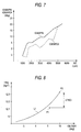
- Fig. 7 is a view showing an example of relationships between the engine revolution number NE and the set map values of IGMAPIN and IGMAPEX in the case where the inlet pipe absolute pressure PBA is constant.
- the basic exhaust ignition timing IGMAPEX is set to lag.
- the basic exhaust ignition timing IGMAPEX is set as the basic intake ignition timing IGMAPIN which is calculated in step S11, and the control then advances to step S15.
- step S15 a correcting term IGCR is calculated in accordance with the temperature of the engine or the like. Then, intake ignition timing IGLOGIN and exhaust ignition timing IGLOGEX are calculated by adding the correcting term to the basic ignition timings IGMAPIN and IGMAPEX (step S16).
- the ignition signals SIG1 to SIG4 are generated, and then supplied to the ignition plugs 8.
- the operating region where simultaneous ignition in which the ignition timings IGLOGIN and IGLOGEX of the two ignition plugs disposed in one cylinder, i.e., intake and exhaust ignition plugs 8I and 8E are equal to each other is to be performed, and the operating region where the phase-difference ignition is to be performed are set. Only when the operation state of the engine is in the phase-difference ignition region, the IGMAPEX map is searched, and, when the operation state is in the operating region where simultaneous ignition is to be performed, the map search is not performed, and the basic exhaust ignition timing IGMAPEX is set as the basic intake ignition timing IGMAPIN.
- phase-difference ignition is performed only in the operating region where the effect of the phase-difference ignition is remarkably achieved. Therefore, the calculation load on the CPU of the ECU 11 can be reduced, and also the capacity of a memory required for storing the IGMAPEX map can be reduced.
- Fig. 8 is a view showing relationships between the intake ignition timing IGLOGIN and the output torque TRQ of the engine, in case that the engine revolution number NE is 2500rpm and the operation state is in the full throttle.
- the line L1 shows characteristics in the case where the exhaust ignition timing IGLOGEX is optimumly set in accordance with the basic intake ignition timing IGLOGIN
- An air-fuel mixture flows into the combustion chamber 3 of the engine 1 in the direction of the arrow X in Fig. 2, to cause a clockwise swirl therein.
- ignition by the intake ignition plug 8I1 is first performed, combustion proceeds from the vicinity of the ignition plug 8I1 toward the exhaust ignition plug 8E1.
- the ignition of the exhaust ignition plug 8E1 is performed after one of the intake ignition plug 8I1 so that normal combustion can be done before abnormal ignition of a so-called end gas part occurs (before knocking is caused). Therefore, the ignition timing at which the engine output torque is maximum can be set without causing knocking.
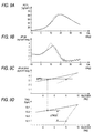
- Fig. 9A shows relationships between the basic exhaust ignition timing IGLOGEX and the maximum rate of change dP/d ⁇ MAX in the case where the intake ignition timing IGLOGIN is fixed to 10 deg.
- the solid line in Fig. 9D shows relationships between the exhaust ignition timing IGLOGEX and the engine output torque TRQ in the case of the same setting.
- vibration noises are higher in level as the maximum rate of change dP/d ⁇ MAX is larger.
- the maximum rate of change dP/d ⁇ MAX is suppressed to the threshold DPTH of Fig. 9C or less, for example, the engine output torque in the phase-difference ignition can be therefore increased by ⁇ TRQ2 as compared with that in the simultaneous ignition.
- the air-fuel ratio can be set to a leaner value, so that the fuel consumption can be improved and the amount of exhaust gas recirculation can be increased. Therefore, it is possible to attain also an effect that exhaust emission characteristics are improved.
- the ECU 11 constitutes an ignition timing control device.
- the intake ignition timing IGLOGIN is set to lead the exhaust ignition timing IGLOGEX.
- the invention is not restricted to this timing relationship.
- the exhaust ignition timing IGLOGEX may be set to lead the intake ignition timing IGLOGIN.
- the knocking suppressing effect can be attained by setting the intake ignition timing IGLOGIN so that ignition is performed before abnormal ignition of an end gas part occurs.
- the configuration (Fig. 3) in which the two ignition plugs are driven by the one ignition signal is employed.
- a configuration in which an ignition signal is generated for each of ignition plugs and the ignition plugs are driven respectively by the ignition signals may be employed.
- the two ignition plugs ignite at different ignition timings. And, in the operating region other than the predetermined operating region, the ignition plugs ignite at the same ignition timing.
- the predetermined operating region is restricted to a region where the effect of the setting of different ignition timings is remarkably achieved, therefore, the load on a calculation unit and the memory capacity can be reduced. In the predetermined operating region, an excellent effect of suppressing knocking and vibration noises can be attained by the setting of different ignition timings.
- An engine operating region in which two ignition plugs ignite at different ignition timings is restricted to a region (phase-difference ignition region) where the effect of different ignition timings is remarkably achieved.
- simultaneous ignition is performed.
- a basic ignition timing IGMAPIN of the intake ignition plugs 8I is calculated by searching a map (S11).
- a basic ignition timing IGMAPEX of exhaust ignition plugs 8E is calculated by searching a map (S13).
- the basic exhaust ignition timing IGMAPEX is set as the basic intake ignition timing IGMAPIN (S14).
Landscapes
- Engineering & Computer Science (AREA)
- Chemical & Material Sciences (AREA)
- Combustion & Propulsion (AREA)
- Mechanical Engineering (AREA)
- General Engineering & Computer Science (AREA)
- Electrical Control Of Ignition Timing (AREA)
- Ignition Installations For Internal Combustion Engines (AREA)
- Combustion Methods Of Internal-Combustion Engines (AREA)
Applications Claiming Priority (2)
| Application Number | Priority Date | Filing Date | Title |
|---|---|---|---|
| JP2000105877A JP4275289B2 (ja) | 2000-04-07 | 2000-04-07 | 内燃機関の点火時期制御装置 |
| JP2000105877 | 2000-04-07 |
Publications (3)
| Publication Number | Publication Date |
|---|---|
| EP1143142A2 true EP1143142A2 (de) | 2001-10-10 |
| EP1143142A3 EP1143142A3 (de) | 2005-04-06 |
| EP1143142B1 EP1143142B1 (de) | 2008-09-03 |
Family
ID=18619136
Family Applications (1)
| Application Number | Title | Priority Date | Filing Date |
|---|---|---|---|
| EP01108776A Expired - Lifetime EP1143142B1 (de) | 2000-04-07 | 2001-04-06 | Zündzeitpunktsteuereinheit für einen Verbrennungsmotor |
Country Status (6)
| Country | Link |
|---|---|
| US (1) | US6499460B2 (de) |
| EP (1) | EP1143142B1 (de) |
| JP (1) | JP4275289B2 (de) |
| CN (1) | CN1214185C (de) |
| DE (1) | DE60135597D1 (de) |
| TW (1) | TW502084B (de) |
Cited By (1)
| Publication number | Priority date | Publication date | Assignee | Title |
|---|---|---|---|---|
| DE10222078B4 (de) * | 2001-05-17 | 2007-04-12 | Honda Giken Kogyo K.K. | Mehrzylindermotor |
Families Citing this family (14)
| Publication number | Priority date | Publication date | Assignee | Title |
|---|---|---|---|---|
| US7778596B2 (en) | 2004-07-29 | 2010-08-17 | Qualcomm Incorporated | Airlink sensing watermarking repeater |
| CN101213368A (zh) * | 2005-07-01 | 2008-07-02 | 百佳车辆有限公司 | 用于控制发动机噪声的方法及系统 |
| JP2007092692A (ja) * | 2005-09-29 | 2007-04-12 | Toyota Motor Corp | 内燃機関 |
| DE102008003842A1 (de) * | 2008-01-10 | 2009-07-16 | Robert Bosch Gmbh | Verfahren zum Verbrennen von Kraftstoff |
| US7832259B2 (en) * | 2008-06-16 | 2010-11-16 | Gm Global Technology Operations, Inc. | Fuel system diagnostics by analyzing engine crankshaft speed signal |
| US8176893B2 (en) * | 2008-08-30 | 2012-05-15 | Ford Global Technologies, Llc | Engine combustion control using ion sense feedback |
| JP5429225B2 (ja) * | 2011-04-19 | 2014-02-26 | マツダ株式会社 | 火花点火式エンジン |
| TWI414677B (zh) * | 2011-07-13 | 2013-11-11 | Kwang Yang Motor Co | Multi - cylinder internal combustion engine |
| DE102014220915B4 (de) * | 2013-11-13 | 2020-06-18 | Suzuki Motor Corporation | Zündsteuervorrichtung für Motor |
| JP2021161974A (ja) * | 2020-03-31 | 2021-10-11 | 本田技研工業株式会社 | 燃料噴射制御装置 |
| JP7119019B2 (ja) * | 2020-03-31 | 2022-08-16 | 本田技研工業株式会社 | 内燃機関の制御装置 |
| JP7661824B2 (ja) * | 2021-07-30 | 2025-04-15 | マツダ株式会社 | エンジンシステム |
| JP7647425B2 (ja) * | 2021-07-30 | 2025-03-18 | マツダ株式会社 | エンジンシステム |
| DE102024206726A1 (de) | 2024-07-17 | 2026-01-22 | Robert Bosch Gesellschaft mit beschränkter Haftung | Verfahren zum Bestimmen einer Zündwinkeleffizienz und Verfahren zum Bestimmen einer Kombination von Zündwinkeln |
Citations (1)
| Publication number | Priority date | Publication date | Assignee | Title |
|---|---|---|---|---|
| JPH06323230A (ja) | 1993-05-18 | 1994-11-22 | Mazda Motor Corp | 多点点火エンジンの点火時期制御装置 |
Family Cites Families (13)
| Publication number | Priority date | Publication date | Assignee | Title |
|---|---|---|---|---|
| JPS5294911A (en) * | 1976-02-06 | 1977-08-10 | Nissan Motor Co Ltd | Two points firing engine |
| JPS6010165B2 (ja) * | 1976-02-06 | 1985-03-15 | 日産自動車株式会社 | 2点着火エンジン |
| JPS6010163B2 (ja) * | 1976-02-16 | 1985-03-15 | 日産自動車株式会社 | 自動車用エンジンのシリンダヘツド |
| JPS569060Y2 (de) * | 1976-04-16 | 1981-02-27 | ||
| JPS5650146Y2 (de) * | 1977-04-29 | 1981-11-24 | ||
| GB2070135B (en) * | 1980-02-12 | 1984-02-01 | Nissan Motor | Spark-ignition internal combustion engine |
| JPS5746065A (en) * | 1980-09-01 | 1982-03-16 | Mazda Motor Corp | Ignition system of engine |
| JPS58210371A (ja) * | 1982-06-01 | 1983-12-07 | Nissan Motor Co Ltd | 2点着火エンジン |
| US4452198A (en) * | 1982-06-28 | 1984-06-05 | General Motors Corporation | Compact dual spark internal combustion engine |
| JP3105235B2 (ja) * | 1990-03-30 | 2000-10-30 | マツダ株式会社 | エンジン |
| JPH05141336A (ja) * | 1991-11-22 | 1993-06-08 | Honda Motor Co Ltd | 内燃機関の点火装置 |
| WO1997048905A1 (en) * | 1996-06-20 | 1997-12-24 | Mecel Ab | Method for ignition control in combustion engines |
| JP3596325B2 (ja) * | 1999-02-09 | 2004-12-02 | 日産自動車株式会社 | 内燃機関のアイドル運転制御装置 |
-
2000
- 2000-04-07 JP JP2000105877A patent/JP4275289B2/ja not_active Expired - Fee Related
-
2001
- 2001-04-06 EP EP01108776A patent/EP1143142B1/de not_active Expired - Lifetime
- 2001-04-06 DE DE60135597T patent/DE60135597D1/de not_active Expired - Fee Related
- 2001-04-06 CN CN01112489.XA patent/CN1214185C/zh not_active Expired - Fee Related
- 2001-04-06 TW TW090108341A patent/TW502084B/zh not_active IP Right Cessation
- 2001-04-06 US US09/827,373 patent/US6499460B2/en not_active Expired - Fee Related
Patent Citations (1)
| Publication number | Priority date | Publication date | Assignee | Title |
|---|---|---|---|---|
| JPH06323230A (ja) | 1993-05-18 | 1994-11-22 | Mazda Motor Corp | 多点点火エンジンの点火時期制御装置 |
Cited By (1)
| Publication number | Priority date | Publication date | Assignee | Title |
|---|---|---|---|---|
| DE10222078B4 (de) * | 2001-05-17 | 2007-04-12 | Honda Giken Kogyo K.K. | Mehrzylindermotor |
Also Published As
| Publication number | Publication date |
|---|---|
| DE60135597D1 (de) | 2008-10-16 |
| EP1143142B1 (de) | 2008-09-03 |
| EP1143142A3 (de) | 2005-04-06 |
| TW502084B (en) | 2002-09-11 |
| CN1317640A (zh) | 2001-10-17 |
| JP4275289B2 (ja) | 2009-06-10 |
| JP2001289143A (ja) | 2001-10-19 |
| CN1214185C (zh) | 2005-08-10 |
| US20020038655A1 (en) | 2002-04-04 |
| US6499460B2 (en) | 2002-12-31 |
Similar Documents
| Publication | Publication Date | Title |
|---|---|---|
| US5088318A (en) | Determining device for determining a failure in an engine cylinder | |
| US5690073A (en) | Fuel injection control device of a multi-cylinder engine | |
| EP1143142B1 (de) | Zündzeitpunktsteuereinheit für einen Verbrennungsmotor | |
| JPH094500A (ja) | 2サイクル筒内噴射エンジンの制御装置 | |
| EP1793110A2 (de) | System zur Steuerung einer Brennkraftmaschine | |
| JP3976322B2 (ja) | エンジン制御装置 | |
| US20040107947A1 (en) | Fuel injection system and control method for internal combustion engine starting time | |
| JP3191676B2 (ja) | 内燃機関の点火時期制御装置 | |
| JPH08246933A (ja) | エンジンの燃料供給装置 | |
| JP7586313B2 (ja) | 内燃機関の排気還流制御方法および制御装置 | |
| JPH10141097A (ja) | 内燃機関の制御装置、バルブタイミング制御装置及びバルブタイミング制御方法 | |
| US8490599B2 (en) | Abnormality determination apparatus and abnormality determination method for internal combustion engine | |
| JP3265999B2 (ja) | 筒内噴射型内燃機関のノック制御装置 | |
| JPS608446A (ja) | 内燃機関用制御装置 | |
| JPH05550B2 (de) | ||
| EP4664089A1 (de) | Fehlzündungserkennungsvorrichtung und fehlzündungserkennungsverfahren für einen verbrennungsmotor | |
| JP2010138720A (ja) | エンジンの点火制御装置 | |
| JP2007009835A (ja) | 内燃機関の制御装置 | |
| JP2005016343A (ja) | 圧縮着火式内燃機関の制御装置 | |
| JP3519946B2 (ja) | 内燃機関の燃料噴射制御装置 | |
| JPH04101067A (ja) | 内燃機関の点火時期制御装置 | |
| JP3525689B2 (ja) | 燃料噴射装置 | |
| JPH01211627A (ja) | エンジンの制御装置 | |
| JP2001153013A (ja) | 内燃機関の点火時期制御方法 | |
| JPS6380028A (ja) | 燃料噴射量制御装置 |
Legal Events
| Date | Code | Title | Description |
|---|---|---|---|
| PUAI | Public reference made under article 153(3) epc to a published international application that has entered the european phase |
Free format text: ORIGINAL CODE: 0009012 |
|
| AK | Designated contracting states |
Kind code of ref document: A2 Designated state(s): AT BE CH CY DE DK ES FI FR GB GR IE IT LI LU MC NL PT SE TR |
|
| AX | Request for extension of the european patent |
Free format text: AL;LT;LV;MK;RO;SI |
|
| PUAL | Search report despatched |
Free format text: ORIGINAL CODE: 0009013 |
|
| AK | Designated contracting states |
Kind code of ref document: A3 Designated state(s): AT BE CH CY DE DK ES FI FR GB GR IE IT LI LU MC NL PT SE TR |
|
| AX | Request for extension of the european patent |
Extension state: AL LT LV MK RO SI |
|
| RIC1 | Information provided on ipc code assigned before grant |
Ipc: 7F 02P 15/02 B Ipc: 7F 02P 15/08 A |
|
| 17P | Request for examination filed |
Effective date: 20050708 |
|
| AKX | Designation fees paid |
Designated state(s): DE GB |
|
| 17Q | First examination report despatched |
Effective date: 20060130 |
|
| GRAP | Despatch of communication of intention to grant a patent |
Free format text: ORIGINAL CODE: EPIDOSNIGR1 |
|
| GRAS | Grant fee paid |
Free format text: ORIGINAL CODE: EPIDOSNIGR3 |
|
| GRAA | (expected) grant |
Free format text: ORIGINAL CODE: 0009210 |
|
| AK | Designated contracting states |
Kind code of ref document: B1 Designated state(s): DE GB |
|
| REG | Reference to a national code |
Ref country code: GB Ref legal event code: FG4D |
|
| REF | Corresponds to: |
Ref document number: 60135597 Country of ref document: DE Date of ref document: 20081016 Kind code of ref document: P |
|
| PLBE | No opposition filed within time limit |
Free format text: ORIGINAL CODE: 0009261 |
|
| STAA | Information on the status of an ep patent application or granted ep patent |
Free format text: STATUS: NO OPPOSITION FILED WITHIN TIME LIMIT |
|
| 26N | No opposition filed |
Effective date: 20090604 |
|
| PGFP | Annual fee paid to national office [announced via postgrant information from national office to epo] |
Ref country code: DE Payment date: 20090402 Year of fee payment: 9 |
|
| PGFP | Annual fee paid to national office [announced via postgrant information from national office to epo] |
Ref country code: GB Payment date: 20090401 Year of fee payment: 9 |
|
| GBPC | Gb: european patent ceased through non-payment of renewal fee |
Effective date: 20100406 |
|
| PG25 | Lapsed in a contracting state [announced via postgrant information from national office to epo] |
Ref country code: DE Free format text: LAPSE BECAUSE OF NON-PAYMENT OF DUE FEES Effective date: 20101103 |
|
| PG25 | Lapsed in a contracting state [announced via postgrant information from national office to epo] |
Ref country code: GB Free format text: LAPSE BECAUSE OF NON-PAYMENT OF DUE FEES Effective date: 20100406 |