EP1143426A2 - Informationsaufzeichnungssysem und Informationsaufzeichnungsverfahren - Google Patents
Informationsaufzeichnungssysem und Informationsaufzeichnungsverfahren Download PDFInfo
- Publication number
- EP1143426A2 EP1143426A2 EP01107918A EP01107918A EP1143426A2 EP 1143426 A2 EP1143426 A2 EP 1143426A2 EP 01107918 A EP01107918 A EP 01107918A EP 01107918 A EP01107918 A EP 01107918A EP 1143426 A2 EP1143426 A2 EP 1143426A2
- Authority
- EP
- European Patent Office
- Prior art keywords
- data
- information
- image pattern
- pit art
- recording
- Prior art date
- Legal status (The legal status is an assumption and is not a legal conclusion. Google has not performed a legal analysis and makes no representation as to the accuracy of the status listed.)
- Withdrawn
Links
Images




Classifications
-
- G—PHYSICS
- G11—INFORMATION STORAGE
- G11B—INFORMATION STORAGE BASED ON RELATIVE MOVEMENT BETWEEN RECORD CARRIER AND TRANSDUCER
- G11B7/00—Recording or reproducing by optical means, e.g. recording using a thermal beam of optical radiation by modifying optical properties or the physical structure, reproducing using an optical beam at lower power by sensing optical properties; Record carriers therefor
- G11B7/24—Record carriers characterised by shape, structure or physical properties, or by the selection of the material
- G11B7/24094—Indication parts or information parts for identification
-
- G—PHYSICS
- G11—INFORMATION STORAGE
- G11B—INFORMATION STORAGE BASED ON RELATIVE MOVEMENT BETWEEN RECORD CARRIER AND TRANSDUCER
- G11B23/00—Record carriers not specific to the method of recording or reproducing; Accessories, e.g. containers, specially adapted for co-operation with the recording or reproducing apparatus ; Intermediate mediums; Apparatus or processes specially adapted for their manufacture
- G11B23/38—Visual features other than those contained in record tracks or represented by sprocket holes the visual signals being auxiliary signals
- G11B23/40—Identifying or analogous means applied to or incorporated in the record carrier and not intended for visual display simultaneously with the playing-back of the record carrier, e.g. label, leader, photograph
-
- G—PHYSICS
- G11—INFORMATION STORAGE
- G11B—INFORMATION STORAGE BASED ON RELATIVE MOVEMENT BETWEEN RECORD CARRIER AND TRANSDUCER
- G11B27/00—Editing; Indexing; Addressing; Timing or synchronising; Monitoring; Measuring tape travel
- G11B27/10—Indexing; Addressing; Timing or synchronising; Measuring tape travel
- G11B27/11—Indexing; Addressing; Timing or synchronising; Measuring tape travel by using information not detectable on the record carrier
-
- G—PHYSICS
- G11—INFORMATION STORAGE
- G11B—INFORMATION STORAGE BASED ON RELATIVE MOVEMENT BETWEEN RECORD CARRIER AND TRANSDUCER
- G11B27/00—Editing; Indexing; Addressing; Timing or synchronising; Monitoring; Measuring tape travel
- G11B27/10—Indexing; Addressing; Timing or synchronising; Measuring tape travel
- G11B27/19—Indexing; Addressing; Timing or synchronising; Measuring tape travel by using information detectable on the record carrier
- G11B27/28—Indexing; Addressing; Timing or synchronising; Measuring tape travel by using information detectable on the record carrier by using information signals recorded by the same method as the main recording
- G11B27/32—Indexing; Addressing; Timing or synchronising; Measuring tape travel by using information detectable on the record carrier by using information signals recorded by the same method as the main recording on separate auxiliary tracks of the same or an auxiliary record carrier
- G11B27/327—Table of contents
- G11B27/329—Table of contents on a disc [VTOC]
-
- G—PHYSICS
- G11—INFORMATION STORAGE
- G11B—INFORMATION STORAGE BASED ON RELATIVE MOVEMENT BETWEEN RECORD CARRIER AND TRANSDUCER
- G11B27/00—Editing; Indexing; Addressing; Timing or synchronising; Monitoring; Measuring tape travel
- G11B27/10—Indexing; Addressing; Timing or synchronising; Measuring tape travel
- G11B27/34—Indicating arrangements
-
- G—PHYSICS
- G11—INFORMATION STORAGE
- G11B—INFORMATION STORAGE BASED ON RELATIVE MOVEMENT BETWEEN RECORD CARRIER AND TRANSDUCER
- G11B27/00—Editing; Indexing; Addressing; Timing or synchronising; Monitoring; Measuring tape travel
- G11B27/36—Monitoring, i.e. supervising the progress of recording or reproducing
-
- G—PHYSICS
- G11—INFORMATION STORAGE
- G11B—INFORMATION STORAGE BASED ON RELATIVE MOVEMENT BETWEEN RECORD CARRIER AND TRANSDUCER
- G11B7/00—Recording or reproducing by optical means, e.g. recording using a thermal beam of optical radiation by modifying optical properties or the physical structure, reproducing using an optical beam at lower power by sensing optical properties; Record carriers therefor
- G11B7/004—Recording, reproducing or erasing methods; Read, write or erase circuits therefor
- G11B7/0045—Recording
-
- G—PHYSICS
- G11—INFORMATION STORAGE
- G11B—INFORMATION STORAGE BASED ON RELATIVE MOVEMENT BETWEEN RECORD CARRIER AND TRANSDUCER
- G11B7/00—Recording or reproducing by optical means, e.g. recording using a thermal beam of optical radiation by modifying optical properties or the physical structure, reproducing using an optical beam at lower power by sensing optical properties; Record carriers therefor
- G11B7/24—Record carriers characterised by shape, structure or physical properties, or by the selection of the material
-
- G—PHYSICS
- G11—INFORMATION STORAGE
- G11B—INFORMATION STORAGE BASED ON RELATIVE MOVEMENT BETWEEN RECORD CARRIER AND TRANSDUCER
- G11B2220/00—Record carriers by type
- G11B2220/20—Disc-shaped record carriers
- G11B2220/21—Disc-shaped record carriers characterised in that the disc is of read-only, rewritable, or recordable type
- G11B2220/213—Read-only discs
-
- G—PHYSICS
- G11—INFORMATION STORAGE
- G11B—INFORMATION STORAGE BASED ON RELATIVE MOVEMENT BETWEEN RECORD CARRIER AND TRANSDUCER
- G11B2220/00—Record carriers by type
- G11B2220/20—Disc-shaped record carriers
- G11B2220/21—Disc-shaped record carriers characterised in that the disc is of read-only, rewritable, or recordable type
- G11B2220/215—Recordable discs
- G11B2220/216—Rewritable discs
-
- G—PHYSICS
- G11—INFORMATION STORAGE
- G11B—INFORMATION STORAGE BASED ON RELATIVE MOVEMENT BETWEEN RECORD CARRIER AND TRANSDUCER
- G11B2220/00—Record carriers by type
- G11B2220/20—Disc-shaped record carriers
- G11B2220/21—Disc-shaped record carriers characterised in that the disc is of read-only, rewritable, or recordable type
- G11B2220/215—Recordable discs
- G11B2220/218—Write-once discs
-
- G—PHYSICS
- G11—INFORMATION STORAGE
- G11B—INFORMATION STORAGE BASED ON RELATIVE MOVEMENT BETWEEN RECORD CARRIER AND TRANSDUCER
- G11B2220/00—Record carriers by type
- G11B2220/20—Disc-shaped record carriers
- G11B2220/25—Disc-shaped record carriers characterised in that the disc is based on a specific recording technology
- G11B2220/2525—Magneto-optical [MO] discs
- G11B2220/2529—Mini-discs
-
- G—PHYSICS
- G11—INFORMATION STORAGE
- G11B—INFORMATION STORAGE BASED ON RELATIVE MOVEMENT BETWEEN RECORD CARRIER AND TRANSDUCER
- G11B2220/00—Record carriers by type
- G11B2220/20—Disc-shaped record carriers
- G11B2220/25—Disc-shaped record carriers characterised in that the disc is based on a specific recording technology
- G11B2220/2537—Optical discs
- G11B2220/2545—CDs
-
- G—PHYSICS
- G11—INFORMATION STORAGE
- G11B—INFORMATION STORAGE BASED ON RELATIVE MOVEMENT BETWEEN RECORD CARRIER AND TRANSDUCER
- G11B2220/00—Record carriers by type
- G11B2220/20—Disc-shaped record carriers
- G11B2220/25—Disc-shaped record carriers characterised in that the disc is based on a specific recording technology
- G11B2220/2537—Optical discs
- G11B2220/2562—DVDs [digital versatile discs]; Digital video discs; MMCDs; HDCDs
-
- G—PHYSICS
- G11—INFORMATION STORAGE
- G11B—INFORMATION STORAGE BASED ON RELATIVE MOVEMENT BETWEEN RECORD CARRIER AND TRANSDUCER
- G11B2220/00—Record carriers by type
- G11B2220/20—Disc-shaped record carriers
- G11B2220/25—Disc-shaped record carriers characterised in that the disc is based on a specific recording technology
- G11B2220/2537—Optical discs
- G11B2220/2562—DVDs [digital versatile discs]; Digital video discs; MMCDs; HDCDs
- G11B2220/2575—DVD-RAMs
-
- G—PHYSICS
- G11—INFORMATION STORAGE
- G11B—INFORMATION STORAGE BASED ON RELATIVE MOVEMENT BETWEEN RECORD CARRIER AND TRANSDUCER
- G11B2220/00—Record carriers by type
- G11B2220/60—Solid state media
- G11B2220/65—Solid state media wherein solid state memory is used for storing indexing information or metadata
Definitions
- the present invention relates to an information recording system provided with a function of recording visible information on an optical recording medium.
- CDs Compact Disk
- DVDs Digital Video Disk or Digital Versatile Disk
- optical recording media for optically recording or reproducing information.
- a write-once type disk and rewritable disk in which information can be recorded have also been developed, providing excellent convenience for users.
- a user can enjoy writing and editing contents data such as music, image or the like and creating his/her own disk having originality by utilizing these write-once type or rewritable disks.
- a user can create discs which offer greater convenience by writing computer program data needed for combining all their essential applications onto a single disc.
- a user can write characters or illustrations by using a writing tool on a side of a conventional disk which is not used for writing information, that is, the back side (hereinafter, referred to as label side) of a side irradiated with light beam for writing and reading information.
- an object of the present invention is to provide an information recording system having a function of recording visible information.
- an aspect of the present invention is an information recording system and an information recording method for recording information on an optical information recording medium, wherein a recording layer formed on the optical recording medium is irradiated with light to generate changes in optical characteristics between a portion irradiated with light and an unirradiated portion in the recording layer so that a visible image pattern is formed.
- Another aspect of the present invention is characterized in that the visible image pattern is formed based on a difference in reflectance between an area where pits are formed by irradiating the recording layer formed on the optical recording medium with light and an area which is not irradiated with light not to form pits.
- a recording layer which is formed in an optical recording medium is irradiated with light by writing means.
- This irradiated light causes changes in optical characteristics of the recording layer.
- a visible image pattern can be formed by forming a portion where the optical characteristics change. That is, the visible image pattern is formed based on the difference in reflectance between an area where pits are formed by irradiating the recording layer with light and an area which is not irradiated light not to form pits.
- An image pattern having an identification property similar to conventional hand-written characters, symbols, illustrations or the like can be formed by forming this visible image pattern into an appropriate shape.
- a digital audio system capable of using a write-once type disk such as CD-R or the like, a rewritable disk such as CD-RW or the like and a disk exclusively for reproduction such as CD-ROM, CD-DA or the like is described as a preferred embodiment.
- pit art As used in description of this embodiment are defined.
- Pit art is an image pattern which is made visible by recording data in a recording layer of a disk such as a CD-R or the like in which data can be written and utilizing the difference in reflectance or the like between a portion where data is recorded and a portion where data is not recorded. That is, unlike ordinary data recording, "pit art” is an image pattern such as characters, illustrations or the like recorded in a recording layer so as to be visible.
- Pit art data is data written to form a "pit art” in a recording layer of a disk.
- Patent recording is to record “pit art data” in a recording layer of a disk, in which data can be written.
- Fig. 2 shows an appearance of this digital audio system.
- Figs. 3 and 4 are block diagrams showing an internal configuration of this digital audio system.
- a front panel 2 of this digital audio system 1 is provided with a disk inserting port 3 for loading and unloading a disk, which is an optical recording medium, and a display unit 4 formed with a liquid crystal display or the like.
- a plurality of operating switches are provided surrounding the disk inserting port 3 and the display unit 4.
- an eject switch 5 for allowing the loading and unloading, a power-on switch 6, a rotary switch 7 for controlling the sound volume, a plurality of function switches 8 disposed to the right side of the display unit 4, a plurality of function switches 9 disposed to the left side of the display unit 4, a recording start switch 10 for instructing the start of recording and a rotary switch 11 called jog dial are provided.
- a movable tray (not shown) for placing a disk thereon is provided in the disk inserting port 3.
- the movable tray is moved back and forth via the disk inserting port 3 so as to load or unload a disk to or from a so-called clamp position.
- the movable tray is projected forward via the disk inserting port 3. Consequently, a disk already loaded can be removed or a new disk can be loaded.
- the eject switch 5 is pressed in a state that the movable tray is projected forward via the disk inserting port 3, the movable tray is automatically moved deep into the disk inserting port 3 and loading is carried out.
- a disk is placed with its label side facing the movable tray. Consequently, a user loads a disk onto or unloads from the movable tray while directing the label side of the disk downward (the movable tray side) with the side of the disk on which data is recorded or reproduced in view.
- the plurality of function switches 8 are constituted by a plurality of operating switches for starting reproduction of data recorded in a disk, temporarily stopping data reproduction, specifying a track number with which data is recorded and so forth.
- the plurality of function switches 9 are constituted by a plurality of operating switches operated when pit art data is written in a write-once type disk or a rewritable disk. More specifically, in addition to a pit art recording start switch for instructing the start of pit art recording, the function switches 9 are constituted by a plurality of editing switches for editing size, arrangement or the like of characters, illustrations or the like to be recorded as a pit art and a settlement switch for settling the edited characters, illustrations or the like.
- the rotary switch 11 called as a jog dial is provided for selecting characters, symbols, illustrations or the like to be recorded as a pit art by a user. Each time the user rotates the rotary switch 11 at a prescribed angle, data of the characters, symbols, illustrations or the like is switched. When the settlement switch is operated, the characters, symbols, illustrations or the like selected by the rotary switch 11 are settled as a pit art.
- external equipment connecting terminals for connecting external equipment such as a CS tuner, BS tuner, CD player, MD player, DVD player or the like and a keyboard connecting terminal for connecting a keyboard are provided on the rear surface of the digital audio system 1.
- a digital input terminal 13 connected to a digital input circuit 12, an analog input terminal 15 connected to an A/D converter 14, a digital output terminal 17 connected to a digital output circuit 16 and an analog output terminal 19 connected to a D/A converter 18 are provided as the external equipment connecting terminals.
- the digital input terminal 13 is composed of an optical digital input terminal or coaxial digital input terminal.
- the digital input circuit 12 converts optical or electrical digital data supplied via the digital input terminal 13 to digital data which can be processed by signals and inputs the data.
- the analog input terminal 15 is provided for inputting analog signals. That is, when external equipment such as a CD player, MD player or the like is connected to the analog input terminal 15 and audio signals reproduced as analog data are supplied from this external equipment, the audio signals are converted to digital data by the A/D converter 14 and inputted into the digital audio system 1.
- the digital output terminal 17 is composed of an optical digital output terminal or coaxial digital output terminal.
- the digital output circuit 16 converts the reproduced digital data obtained by this reproduction to optical or electrical digital data and outputs the data to external equipment via the digital output terminal 17.
- the D/A converter 18 converts digital data reproduced from a write-once type disk, rewritable disk or disk exclusively used for reproduction to analog signals and outputs the signals to the outside via the analog output terminal 19. Consequently, when an analog amplifier connected to a speaker is connected to the analog output terminal 19, reproduced sound can be played by the speaker. When analog equipment such as an analog tape recorder or the like is connected, reproduced sound can be recorded in the analog form.
- the keyboard connecting terminal 20 is connected to a system controller 21 provided with a microprocessor (MPU).
- MPU microprocessor
- An encoder 26 and an LD drive circuit are subordinately connected to the digital input circuit 12 and A/D converter 14 via a two-contacts switching circuit 23 controlled by the system controller 21.
- the encoder 26 is controlled by the system controller 21 and performs EFM (Eight-Fourteen Modulation) and CIRC (Cross Interleave Reed-Solomon Code) interleaving on data D1 inputted from the two-contacts switching circuit 23.
- the data D2 for writing generated during this processing is outputted to the LD drive circuit 27.
- the data D2 for writing is generated based on the pit art data Dp and outputted to the LD drive circuit 27.
- the LD drive circuit 27 is controlled by the system controller 21 and performs power amplification of data D2 for writing from the encoder 26 and supplies the data to a semiconductor laser (not shown) in a pickup 28. Consequently, a recording layer of a disk DSC is irradiated with light modulated by the power amplified data D3 for writing (hereinafter, referred to as writing light) to perform data writing.
- the LD drive circuit 27 irradiates the recording layer of the disk DSC with light having a certain power (hereinafter, referred to as reading light) by supplying a certain power instructed by the system controller 21 to the semiconductor laser in the pickup 28.
- a spindle motor 29 for rotating a clamped disk DSC at a certain linear velocity and a feeding motor 30 for moving the pickup 28 back and forth in the radius direction of the disk DSC are provided at the aforementioned clamp position.
- an optical detector (not shown) in the pickup 28 performs photoelectric conversion of returning light generated in response to the writing light or reading light irradiated on the disk DSC when data is written or read.
- An RF amplifier 31 supplies the photoelectrically converted signals SRF to an address decoder 32, servo control circuit 33 and decoder 34.
- the address decoder 32 detects a track address on the disk DSC irradiated with the writing light or reading light from the photoelectrically converted signals SRF outputted from the RF amplifier 31 and supplies the detected address data D4 to the encoder 26 and the system controller 21.
- the encoder 26 transfers the data D2 for writing in synchronism with the address data D4 to the LD drive circuit 27 when the data is recorded as described above.
- the system controller 21 judges whether the pickup 28 is in an on-track state at the track address on the disk DSC where data is to be written when the data is recorded.
- the decoder 34 receives input of the photoelectrically converted signals SRF outputted from the RF amplifier 31 and the address data D4 outputted from the address decoder 32, and EFM demodulates and deinterleaves audio data or the like included in the photoelectrically converted signals SRF in synchronism with the address data D4. Consequently, decoding processing opposite to processing by the encoder 26 is performed and decoded data D4 generated by this processing is supplied to the digital output circuit 16 and the D/A converter 18.
- the decoder 34 decodes this TOC data and supplies the decoded TOC data Dt2 to the system controller 21.
- the servo control circuit 33 detects tracking error or focusing error based on the photoelectrically converted signals SRF outputted from the RF amplifier 31 and servocontrols the spindle motor 29, feeding motor 30 and pickup 28 based on the detection result.
- a pit art data memory 37 and a standard data memory 38 are connected to the system controller 21 and a pit art data generating partXX 39 shown in Fig. 4 is provided.
- the pit art data generating partXX 39 is constituted by a character data decoding partXX 40, pit art data editing partXX 41 and address generating partXX 42 and generates pit art data Dp under the control of the microprocessor MPU provided in the system controller 21.
- the character data decoding partXX 40 receives input of the character information data from the rotary switch 11 called jog dial and character information data from the keyboard 22 via the microprocessor MPU, retrieves standard character data Dc stored in the standard data memory 38 in advance based on the character information data D6 and supplies the data to the pit art data editing partXX 41.
- the character data decoding partXX 40 receives input of the character information data such as TOC, UTOC (user table of contents) or the like included in the reproduced data and supplies the data to the pit art data editing partXX 41.
- the character data decoding partXX 40 receives input of the character information data Dp included in the data and supplies the data to the pit art data editing partXX 41.
- the pit art data editing partXX 41 converts standard character data Dc to data Dbmp in a bit map format (hereinafter, referred to as bit map data) and stores the data in the pit art data memory 37.
- bit map data a bit map format
- the pit art data editing partXX 41 receives input of the editing instruction data D7 via the microprocessor MPU, edits the bit map data Dbmp according to the editing instruction and stores the data in the pit art data memory 37.
- the address generating partXX 42 generates address data Dr for reading bit map data Dbmp stored in the pit art data memory 37. That is, this partXX judges the position of the pickup 28 in relation to the disk DSC based on the address data D4 supplied from the address decoder 32 via the microprocessor MPU. Then, when the partXX determines that the pickup 28 comes to the position at which a pit art is to be recorded, the partXX accesses the pit art data memory 37 by the address data Dr and supplies the bit map data Dbmp as pit art data Dp for each dot to the encoder 26 via the microprocessor MPU and allows the pickup 28 to record the pit art.
- This digital audio system 1 is provided with three kinds of modes for recording a pit art under the control of the system controller 21.
- a user selects a first mode (hereinafter, external data recording mode) by a function switch 9 and audio data supplied from external equipment such as a CS tuner, BS tuner, CD player, MD player, DVD player or the like connected to the digital input terminal 13 is recorded (copied) in a write-once type disk or a rewritable disk, character information data supplied from a CS tuner or BS tuner, character information data included in TOC data supplied from a CD player or character information data included in UTOC data supplied from an MD player are automatically edited. Then, pit art data Dp generated by automatic editing is written in the write-once type disk or rewritable disk. Thus, a pit art is recorded automatically.
- a first mode hereinafter, external data recording mode
- a third mode (hereinafter, referred to as manual mode) by a function switch 9
- the user can edit pit art data Dp by operating the rotary switch 11 or the keyboard 22.
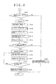
- the TOC data Dt2 which is table of contents information, is reproduced from the disk DSC and stored in a first memory (not shown) in the system controller 21 (step S100).
- step S102 the type of the loaded disk is judged based on the TOC data Dt2 (step S102).
- step S104 whether a recordable disk is loaded is judged.
- a disk exclusively used for reproduction such as a CD-ROM or the like is loaded
- record prohibition processing such as displaying a message in the display unit 4 to the effect that data cannot be recorded is performed (step S106). Then, the processing is forcibly terminated.
- step S108 when the disk DSC is a CD-R, it is determined that a recordable disk is loaded and the processing proceeds to step S108.
- step S108 whether a recording start switch 10 is turned on is judged and the processing remains in a standby state until the switch is turned on. In this standby state, the user starts reproduction by the CD player, which is external equipment. When the user further turns on the recording start switch 10, data reproduced from the CD player is inputted as input data D1.
- the encoder 26 acquires TOC data Dt1, which is table of contents information included in the input data D1. This data is stored in a second memory (not shown) in the system controller 21 (step S110).
- the pickup 28 is moved to a recording start address on a disk DSC. If data is already recorded in the disk DSC, a new track number TRNO is obtained by adding 1 to the track number TRNO assigned to the data (step S112).
- the encoder 26 encodes the input data D1 and starts recording the data by the pickup 28 by using the new track number TRNO as a first track number (step S114).
- step S116 whether the track number assigned to the data D1 from the CD player, which is a copy source, is changed is judged. If the track number is not changed, data recording in step S114 is continued.
- step S116 determines whether the track number assigned to the data D1 is changed.
- step S118 determines whether supply of the data D1 from the CD player is finished.
- step S112 the next track number is set and recording of the data D1 is continued (step S114).
- step S120 When all the data D1 from the CD player is recorded, the processing proceeds to step S120 and finalization processing is performed.
- the table of contents information about the data D1 recorded so far is written in a read-in area of the disk DSC together with TOC data Dt2.
- step S122 After data is further recorded in a read-out area, the processing is halted (step S122) and then proceeds to step S200 in Fig. 6.
- step S200 in Fig. 6 whether the user turns on a pit art recording start switch among the function switches 9 during the halt state is judged.
- the processing proceeds to step S202 and pit art recording prohibition processing is performed. Then a series of data recording processing is terminated without carrying out pit art recording.
- step S204 when the pit art recording start switch is turned on, the processing is halted (step S204) and then proceeds to step S206.
- step S206 the first address ADRS of an unrecorded area remaining in the disk DSC is detected from the TOC data Dt2 acquired in step S100 and the table of contents information data written in step S120. Further, a terminal end address ADRE of the unrecorded area is detected based on the maximum read-out start position information (position information indicating the latest address among position information standardized as read-out recording start address) recorded as ATIP information in a wobbled portion of the read-in area. Then, these address data ADRS and ADRE are supplied to the pit art data editing partXX 41 shown in Fig. 3 with data D7 for editing instruction.
- the pit art data editing partXX 41 calculates the shape of the unrecorded area based on the address data ADRS and ADRE. That is, as shown in Fig. 7, the width W of the unrecorded area in the radius direction of the disk DSC is calculated and the shape of the unrecorded area in an annular shape matching the width W is obtained.
- step S208 character information data D6 (data such as album titles, names of music pieces, artist names and the like) conforming to the CD-TEXT standard included in the TOC data Dt1 stored in the second memory is supplied to the character data decoding partXX 40 shown in Fig. 4.
- step S210 the character data decoding partXX 40 retrieves standard character data Dc corresponding to the character information data D6 and supplies the data to the pit art data editing partXX 41.
- the pit art data editing partXX 41 converts the standard character data Dc to bit map data Dbmp.
- step S212 the pit art data editing partXX 41 compares the size of the bit map data Dbmp and the shape of the unrecorded area and automatically edits the resolution (dot density per unit area) and size of the bit map data Dbmp so that the pit art does not overflow from the unrecorded area. Then, the edited bit map data Dbmp is stored in the bit art data memory 37.
- step S214 the bit map data Dbmp stored in the pit art data memory 37 is supplied to the display unit 4 through the microcomputer MPU.
- a display indicating how the pit art is formed in the unrecorded area of the disk DSC is presented. That is, a preview is displayed.
- Fig. 8 shows an example of a preview display.
- the character information data D6 is an album title "ABCDE”
- the shapes of the disk DSC and the unrecorded area are displayed.
- Bit map data Dbmp of the edited "ABCDE” is further displayed in the display of the unrecorded area.
- the user can view in advance the size, layout and the like of characters "ABCDE" to be recorded as a pit art.
- step S218 when continuation of pit art recording is instructed by the function switch 9 in response to this preview display in step S216, the processing proceeds to step S218.
- step S202 pit art recording prohibition processing is performed to terminate a series of data recording processing. For example, if the user views the preview display and determines that the characters of "ABCDE" to be recorded as a pit art are too small, that the position of the pit art in the unrecorded area is not appropriate or the like, unnecessary pit art recording is not performed by instructing to terminate the pit art recording.
- the processing may automatically proceeds to step S202 so that pit art recording is not performed.
- the pit art data editing partXX 41 automatically edits the resolution (dot density per unit area) and the size of the bit map data Dbmp in step S212 as well, the bit map data Dbmp is automatically edited based on the annular unrecorded portion of N1 tracks and the shape of unrecorded area existent outside of the annular pit art portion of N2 tracks in the radius direction.
- step S220 the pickup 28 is positioned at an address located outside in the radius direction of the disk DSC of the portion where the annular pit art is formed. Further, in step S222, the first one dot of the bit map data Dbmp is read from the pit art data memory 37 and written in the unrecorded area of the disk DSC when supplied to the pickup 28 as pit art data Dp.
- step S224 whether pit art recording is completed is judged in step S224. If the recording is not completed, the processing goes back to step S220 and the bit map data Dbmp of the next one dot is supplied to the pickup 28 as pit art data Dp and recorded at the next address of the unrecorded area (step S222).
- the display unit 4 displays a message to the effect that pit art recording is completed in step S226 and then pit art recording is terminated.
- a pit art PA1 composed of annular pit strings indicating a border of the recorded area and the unrecorded area and a character pit art PA2 such as "ABCDE" or the like are formed.
- the annular pit art PA1 and the character portion of the pit art PA2 are recorded as a multiplicity of pits in the recording layer of the CD-R and pits are not formed in the background portion. Since the reflectance of the portion where pits are formed is different from that of the portion where pits are not formed, a pit art PA2 such as "ABCDE" is visible due to this difference in reflectance.
- the recorded area and the unrecorded area can be distinguished only by viewing the annular pit art PA1. Therefore, the user can judge that the unrecorded area where the pit art PA2 is formed can be touched by hand, but the recorded area where data is recorded should not be touched.
- the recording layer of the CD-R is formed with organic dye, a pit art can be formed clearly when a pit art is recorded.
- a pit art is recorded in a CD-R having a recording layer formed with cyanine or azo dye, a pit art with high contrast can be formed.
- a CD-R is loaded or unloaded in this digital audio system 1 with the recording layer side up and the label side down, the user can handle the CD-R while viewing the pit art. Therefore, the user can readily manage or identify disks according to the pit art and thus convenience of a pit art can be more effectively provided.
- a CD-R may be loaded/unloaded with the recording layer side down and the label side up and a pit art may be recorded from the recording layer side facing downward.
- step S120 processing for pit art recording shown in Fig. 6 is performed.
- the processing for pit art recording may be started without finalization processing as a modification.
- step S120 when writing of the data D1 is completed, table of contents information assigned to data D1 is recorded as temporary TOC in a program management area (PMA) inside the read-in area of the disk DSC. Then, processing for pit art recording shown in Fig. 6 is performed.
- PMA program management area
- the start address ADRS of the unrecorded area is detected based on the temporary TOC information.
- the position of a track being relatively many tracks away from the start address ADRS outward in the radius direction is assumed as the first position where a pit art can be recorded.
- Pit art editing and preview displaying are carried out by assuming the unrecorded area further outward from the start position in the radius direction as an area where a pit art can be recorded.
- annular pit art PA1 and pit art PA2 are recorded in steps S218-S224 as well, these annular pit art PA1 and pit art PA2 are recorded in the unrecorded area outside of a position being 10,000-30,000 tracks away from the start address ADRS outward in the radius direction.
- the unrecorded area of N1 tracks shown in Fig. 9 is secured for 10,000-30,000 tracks and so-called partial disk can be created. Consequently, the user can additionally record data in the unrecorded area secured for 10,000-30,000 tracks. Therefore, a partial disk which is more convenient and can be easily managed or the like by the recorded pit art can be provided.
- the user may select the desired number of tracks in a range of this number of tracks or the user may specify the desired number of tracks without limitation of the number of tracks. Or, the user may specify the number of tracks as an amount converted to time to secure the specified unrecorded area as an additionally recordable area.
- a finalized CD-R that is, a CD-R in which TOC information is already recorded in the read-in area and data is recorded in the read-out area, in the digital audio system 1 and a pit art is recorded in this CD-R.
- step S304 Based on the TOC data Dt2 in the first memory, the type of the disk is judged.
- step S306 whether a recordable disk is loaded is judged.
- a disk exclusively used for reproduction such as a CD-ROM or the like is loaded
- record prohibition processing such as displaying a message in the display unit 4 to the effect that data cannot be recorded is performed (step S308). Then, the processing is forcibly terminated.
- the disk DSC is a CD-R
- it is determined that a recordable disk is loaded and the processing proceeds to step S310.
- a first address ADRS of an unrecorded area remaining in the disk DSC is detected from the TOC data Dt2 in the first memory. Further, a terminal end address ADRE of the unrecorded area is detected based on the maximum read-out start position information (position information indicating the latest address among position information standardized as read-out recording start address) recorded as ATIP information in a wobbled portion of the read-in area. Then, these address data ADRS and ADRE are supplied to the pit art data editing partXX 41 shown in Fig. 4 together with data D7 for edit instruction.
- the pit art data editing partXX 41 calculates the shape of the unrecorded area based on the address data ADRS and ADRE. That is, as shown in Fig. 7, the width W of the unrecorded area in the disk DSC radius direction is calculated and the shape of the unrecorded area in an annular shape matching the width W is obtained. In this step S310 as well as in step S206 in Fig. 6, the width W and shape of the unrecorded area N1 tracks outward in the radius direction from the start address ADRS of the unrecorded area is calculated.
- step S312 character information data D6 (data such as album titles, names of music pieces, artist names and the like) included in the TOC data Dt1 stored in the first memory is supplied to the character data decoding partXX 40 shown in Fig. 4.
- step S314 the character data decoding partXX 40 retrieves standard character data Dc corresponding to the character information data D6 and supplies the data to the pit art data editing partXX 41.
- the pit art data editing partXX 41 converts the standard character data Dc to bit map data Dbmp.
- step S316 the pit art data editing partXX 41 compares the size of the bit map data Dbmp and the shape of the unrecorded area and automatically edits the resolution (dot density per unit area) and size of the bit map data Dbmp so that the pit art does not overflow from the unrecorded area. Then, the edited bit map data Dbmp is stored in the pit art data memory 37.
- step S3108 the bit map data Dbmp stored in the pit art data memory 37 is supplied to the display unit 4 through the microcomputer MPU.
- the character information data D6 is an album title "ABCDE"
- the shapes of the disk DSC and the unrecorded area are displayed.
- Bit map data Dbmp of the edited "ABCDE” is further displayed in the display of the unrecorded area. Based on this bit map data Dbmp, a message for prompting an instruction about whether pit art recording can be started, for example, "DO YOU WANT TO RECORD THE DISPLAYED IMAGE?" or the like is displayed.
- step S320 when continuation of pit art recording is instructed by the function switch 9 in response to this preview display in step S320, the processing proceeds to step S322. On the other hand, if an instruction not to perform pit art recording is given by the function switch 9, the processing proceeds to step S308 and pit art recording prohibition processing is performed to terminate a series of data recording processing.
- step S322 the pickup 28 is moved from the start address ADRS of the unrecorded area to a position being N1 tracks away. A portion of N2 tracks from this position is irradiated with writing light having a prescribed power. Consequently, an annular pit art PA1 indicating a border of the unrecorded area and the recorded area is formed.
- step S324 the pickup 28 is positioned at an address of the portion where the annular pit art is formed, the address being positioned outside in the radius direction of the disk DSC. Further, in step S326, the first one dot of the bit map data Dbmp is read from the pit art data memory 37 and written in the unrecorded area of the disk DSC when supplied to the pickup 28 as pit art data Dp.
- step S328 whether pit art recording is completed is judged. If the recording is not completed, the processing goes back to step S324 and the bit map data Dbmp of the next one dot is supplied to the pickup 28 as pit art data Dp and recorded at the next address of the unrecorded area (step S326).
- the display unit 4 displays a message to the effect that pit art recording is completed in step S330 and then pit art recording is terminated.
- an annular pit art PA1 indicating a border of the recorded area and the unrecorded area and a character pit art PA2 such as "ABCDE" or the like are formed. Since the reflectance of the portion where pits are formed is different from that of the portion where pits are not formed, the user can easily identify or manage disks only by viewing the pit arts PA1 and PA2.
- table of content information data already recorded in the CD-R can be automatically recorded as pit art data. Consequently, benefits such as utilizing a pit art as if data were hand-written and so forth can be provided to a user.
- a pit art can be recorded in a partial disk as well by processing temporary TOC information recorded in the PMA of the partial disk as the TOC information recorded in the finalized CD-R.
- TOC data Dt2 which is table of contents information, is reproduced from the loaded disk DSC and stored in the first memory in the system controller 21 and the processing is halted (step S400).
- steps S402-406 desired characters, symbols, illustrations or the like are inputted by the rotary switch 11 called as a jog dial or the keyboard 22. Whether these characters or the like are selected is judged. If not yet, the processing remains in a standby state until the above input and select operation are carried out (step S402).
- the inputted data such as characters or the like is stored temporarily in a prescribed buffer register and these characters or the like are blinked in the display unit 4.
- the data such as characters or the like in the buffer register is stored in a buffer memory and settled and the aforementioned blinking display is changed to a stationary display (display which does not blink) to indicate that the inputted characters or the like are settled (step S404).
- step S408 when the user inputs the desired character string and operates a prescribed operating switch among the function switches 9 to instruct final settlement of the character string as a pit art, the processing is halted (step S408) and then proceeds to step S410.
- step S408 When the user operates a keyboard 22 and the aforementioned "return key" provided on the keyboard 22 is operated again, the processing proceeds to step S408 and then to step S410.
- step S410 the type of the disk is judged based on the TOC data Dt2 in the first memory.
- step S412 whether a recordable disk is loaded is judged.
- a disk exclusively used for reproduction such as a CD-ROM or the like is loaded
- record prohibition processing such as displaying a message in the display unit 4 to the effect that data cannot be recorded is performed (step S414).
- the manual mode is forcibly terminated.
- the disk DSC is a write-once type disk
- a first address ADRS of an unrecorded area remaining in the write-once disk DSC is detected from the TOC data Dt2 in the first memory. Further, a terminal end address ADRE of the unrecorded area is detected based on the maximum read-out start position information (position information indicating the latest address among position information standardized as read-out recording start address) recorded as ATIP information in a wobbled portion of the read-in area. Then, these address data ADRS and ADRE are supplied to the pit art data editing partXX 41 shown in Fig. 4 together with data D7 for editing instruction.
- the pit art data editing partXX 41 calculates the shape of the unrecorded area based on the address data ADRS and ADRE. That is, as shown in Fig. 7, the width W of the unrecorded area in the radius direction of the disk DSC is calculated and the shape of the unrecorded area in an annular shape matching the width W is obtained.
- step S416 as well as in step S206 in Fig. 6, the width W and shape of the unrecorded area N1 tracks outward in the radius direction from the start address ADRS of the unrecorded area is calculated.
- step S4108 data D6 such as a character string or the like (data such as character string or the like selected by the user) stored in the buffer memory is supplied to a character data decoding partXX 40 shown in Fig. 4.
- step S420 the character data decoding partXX 40 retrieves standard character data Dc corresponding to the data D6 and supplies the data to the pit art data editing partXX 41.
- the pit art data editing partXX 41 converts the standard character data Dc to bit map data Dbmp.
- step S422 the pit art data editing partXX 41 compares the size of the bit map data Dbmp and the shape of the unrecorded area and edits the resolution (dot density per unit area) and size of the bit map data Dbmp so that the pit art does not overflow from the unrecorded area. Then, the edited bit map data Dbmp is stored in the pit art data memory 37.
- step S424 the bit map data Dbmp stored in the pit art data memory 37 is supplied to the display unit 4 through the microcomputer MPU.
- bit map data Dbmp of the edited "ABCDE” is further displayed in the display of the unrecorded area. Based on this bit map data Dbmp, a message for prompting an instruction about whether pit art recording can be started, for example, "DO YOU WANT TO RECORD THE DISPLAYED IMAGE?" or the like is displayed.
- step S428 the processing proceeds to step S428.
- step S414 pit art recording prohibition processing is performed to terminate a series of data recording processing.
- step S428 the pickup 28 is moved from the start address ADRS of the unrecorded area to a position being N1 tracks away outward in the radius direction. Then, a portion of N2 tracks is irradiated with writing light having a prescribed power. Consequently, an annular pit art PA1 indicating a border of the unrecorded area and the recorded area is formed.
- step S430 the pickup 28 is positioned at an address of the portion where the annular pit art PA1 is formed, the address being positioned outside in the radius direction of the disk DSC. Further, in step S432, the first one dot of the bit map data Dbmp is read from the pit art data memory 36 and written in the unrecorded area of the disk DSC when supplied to the pickup 28 as pit art data Dp.
- step S434 whether all the bit map data Dbmp is written in the unrecorded area is judged. If not, the processing goes back to step S430 and the bit map data Dbmp of the next one dot is supplied to the pickup 28 as pit art data Dp and recorded at the next address of the unrecorded area (step S432).
- the display unit 4 displays a message to the effect that pit art recording is completed in step S436 and then pit art recording is terminated.
- an annular pit art PA1 indicating a border of the recorded area and the unrecorded area and a character pit art PA2 such as "ABCDE" or the like are formed. Since the reflectance of the portion where pits are formed is different from that of the portion where pits are not formed, the user can easily identify or manage disks only by viewing the pit arts PA1 and PA2.
- the user can record a desired title or the like as pit art data. Therefore, benefits such as utilizing a pit art as if data were hand-written and so forth can be provided to a user.
- the user can manage or identify a plurality of disks by viewing the patterns.
- a pit art edited by the user is recorded in a finalized CD-R in the manual mode.
- a pit art edited by the user can be recorded in a partial disk as well.
- the pit art can be recorded in a partial disk by processing temporary TOC information recorded in the PMA area of the partial disk as the TOC information recorded in the finalized CD-R.
- a pit art is recorded in a CD-R.
- a pit art can be recorded in optical recording media in which data can be written, such as CD-RW, DVD-R, DVD-RW and the like as well.
- one recordable side can be exclusively used for recording a pit art and the other side can be used as a side for recording usual data.
- part of one recordable side can be used as an area for recording a pit art and part of the other recordable side can also be used as an area for recording a pit art so that pit arts can be formed on both sides and usual data can also be recorded on both sides.
- a pit art such as a character string or the like is arranged in a line
- a character string or the like can be arranged in a circular arc to form a pit art matching the shape of the circular disk.
- a editing function capable of editing pit map data in a various manner may be provided by assuming the whole unrecorded area the same as the conventional label side.
- a pit art is automatically recorded in the external data recording mode and the internal data recording mode.
- the user may edit pit art data by manual operation in these external data recording mode and internal data recording mode as well.
- the shape of the unrecorded area is detected based on the TOC information or temporary TOC information and ATIP information.
- the shape of the unrecorded area may be detected by moving the pickup in the radius direction of the disk DSC and based on the difference in the quantity of returning light (reflected light) from the recorded area and unrecorded area obtained upon this movement.
- the shape of the unrecorded area may be detected or judged not based on the difference in the reflected light quantity from the recorded area and the unrecorded area, but by comparing the reflected light quantity from the recorded area or that from the unrecorded area with a prescribed threshold value or the like.
- both the writing for forming an image pattern (pit art) and normal information writing are performed by one pickup 28 as writing means.
- a pickup for forming an image pattern (pit art) as well as a pickup for normal information writing may be provided.
- bit map data is generated and a pit art is recorded in the recording layer of an optical recording medium by light beam modulated based on the bit map data.
- a pit art may be recorded not only based on the so-called bit map data but also based on data in other data formats.
- a pit art is recorded not only depending on presence of pits, but the size of pits may be adjusted or the interval between pits may be adjusted to record a pit art so that a pit art visually having a plurality of gradations can be recorded. Consequently, a pit art which can express shades, that is, a pit art having an expressive ability can be formed.
- annular pit art PA1 is formed between an area where normal information is recorded (recorded area) and an area where a pit art is to be recorded (unrecorded area) has been described.
- the present invention is not limited to this, but the pit art PA1 does not have to be recorded. The user may select whether this annular pit art PA1 is recorded.
- a recordable player for example, a recordable CD player, DVD player or the like
- a recordable optical recording medium is mounted on a personal computer or the like.
- a computer program having the aforementioned pit art recording function is installed in the personal computer or the like and the computer program is executed by the personal computer so that a pit art is formed on an optical recording medium loaded in the recordable player.
- an optical recording medium in which the computer program is recorded may be provided and installed by using a CD player or DVD player mounted on the personal computer or the like.
- the personal computer or the like may be connected to a network such as the Internet or the like (including connection by telephone line, cable such as LAN or the like or radio) and the computer program is transmitted (downloaded) via the network so as to be set up in the personal computer or the like.
- a recording layer formed in an optical recording medium is irradiated with light and changes in optical characteristics of the portion irradiated with light and the portion not irradiated with light in the recording layer are generated to form a visible image pattern. Therefore, a plurality of optical recording media can be managed or identified by viewing the formed image pattern.
Landscapes
- Optical Recording Or Reproduction (AREA)
- Signal Processing For Digital Recording And Reproducing (AREA)
- Management Or Editing Of Information On Record Carriers (AREA)
- Optical Record Carriers And Manufacture Thereof (AREA)
- Manufacturing Optical Record Carriers (AREA)
Applications Claiming Priority (2)
| Application Number | Priority Date | Filing Date | Title |
|---|---|---|---|
| JP2000098926A JP2001283470A (ja) | 2000-03-31 | 2000-03-31 | 情報記録システム及び情報記録方法 |
| JP2000098926 | 2000-03-31 |
Publications (2)
| Publication Number | Publication Date |
|---|---|
| EP1143426A2 true EP1143426A2 (de) | 2001-10-10 |
| EP1143426A3 EP1143426A3 (de) | 2007-01-10 |
Family
ID=18613348
Family Applications (1)
| Application Number | Title | Priority Date | Filing Date |
|---|---|---|---|
| EP01107918A Withdrawn EP1143426A3 (de) | 2000-03-31 | 2001-03-28 | Informationsaufzeichnungssysem und Informationsaufzeichnungsverfahren |
Country Status (3)
| Country | Link |
|---|---|
| US (6) | US20010040867A1 (de) |
| EP (1) | EP1143426A3 (de) |
| JP (1) | JP2001283470A (de) |
Cited By (9)
| Publication number | Priority date | Publication date | Assignee | Title |
|---|---|---|---|---|
| EP1376567A2 (de) | 2002-06-28 | 2004-01-02 | Yamaha Corporation | Verfahren zur Erzeugung von einem sichtbaren Bild auf einer optischen Platte mittels Laserstrahlung |
| EP1482489A2 (de) | 2003-05-30 | 2004-12-01 | Yamaha Corporation | Optisches Plattengerät und computerlesbares Aufzeichnungsmedium welches ein Programm speichert |
| EP1471529A3 (de) * | 2003-04-23 | 2005-08-24 | Hewlett-Packard Development Company, L.P. | Verfahren zum Etikettieren einer optischen Platte |
| EP1521252A3 (de) * | 2003-09-30 | 2006-12-06 | Yamaha Corporation | Verfahren zur Herstellung eines sichtbaren Bildes, Programm, und System zur Herstellung eines sichtbaren Bildes |
| EP1422697A3 (de) * | 2002-11-15 | 2006-12-06 | Yamaha Corporation | Verfahren, Programm und System zur Erzeugung eines sichtbaren Bildes auf einer optischen Platte |
| EP1308938A3 (de) * | 2001-10-31 | 2007-04-04 | Yamaha Corporation | Gerät zum Aufzeichnen von Daten und sichtbarer Bilder auf eine optische Platte |
| EP1526535A3 (de) * | 2003-10-09 | 2007-09-19 | Hewlett-Packard Development Company, L.P. | Verfahren und System zur Benutzung einer optischen Sensoranordnung zur Steuerung einer Etikettierungsvorrichtung |
| EP1914732A3 (de) * | 2006-10-18 | 2009-01-21 | Yamaha Corporation | Optische Plattenzeichnungsvorrichtung, optisches Plattenzeichnungssystem und optisches Plattenzeichnungsverfahren |
| CN1862672B (zh) * | 2001-10-31 | 2012-05-23 | 雅马哈株式会社 | 能在盘面上投射可见图像的光学记录装置 |
Families Citing this family (40)
| Publication number | Priority date | Publication date | Assignee | Title |
|---|---|---|---|---|
| JP2001283470A (ja) * | 2000-03-31 | 2001-10-12 | Pioneer Electronic Corp | 情報記録システム及び情報記録方法 |
| US7268794B2 (en) * | 2000-10-30 | 2007-09-11 | Yamaha Corporation | Method of printing label on optical disk, optical disk unit, and optical disk |
| JP4244551B2 (ja) * | 2001-11-30 | 2009-03-25 | ソニー株式会社 | 記録再生システム |
| US6771297B2 (en) * | 2002-01-11 | 2004-08-03 | Hewlett-Packard Development Company, L.P. | Labeling apparatus and method for disk storage media |
| KR20030079174A (ko) * | 2002-04-02 | 2003-10-10 | 삼성전자주식회사 | 라벨이 기록된 광 기록매체, 광 기록 매체에 라벨을기록하는 장치 및 방법 |
| JP4225200B2 (ja) * | 2002-04-10 | 2009-02-18 | ソニー株式会社 | 光学記録媒体およびその製造方法 |
| US7145586B2 (en) * | 2002-04-15 | 2006-12-05 | Hewlett-Packard Development Company, L.P. | Marking optical disc based on information related to data side thereof |
| JP4062976B2 (ja) * | 2002-05-31 | 2008-03-19 | ヤマハ株式会社 | 光ディスクへの画像形成装置および画像形成方法 |
| JP3797285B2 (ja) | 2002-06-28 | 2006-07-12 | ヤマハ株式会社 | 光ディスク記録装置の動作制御方法、制御プログラム及び該制御プログラムを記録した記録媒体 |
| JP3758614B2 (ja) | 2002-06-28 | 2006-03-22 | ヤマハ株式会社 | 光ディスク記録装置及び光ディスクに対する画像形成方法 |
| JP4019819B2 (ja) | 2002-06-28 | 2007-12-12 | ヤマハ株式会社 | 光ディスク記録装置 |
| JP4019871B2 (ja) * | 2002-09-18 | 2007-12-12 | ヤマハ株式会社 | 光ディスク記録装置、及び光ディスク記録方法 |
| EP1561219B1 (de) * | 2002-11-06 | 2013-05-29 | Koninklijke Philips Electronics N.V. | Verfahren zum aufzeichnen eines etikettes auf einer optischen platte und entsprechendes plattenlaufwerk |
| MXPA05003297A (es) * | 2003-03-08 | 2005-07-05 | Samsung Electronics Co Ltd | Metodo y aparato para preservar el estado de grabacion de datos de un medio de grabacion grabable una sola vez y medio de grabacion grabable una sola vez para el mismo. |
| US20040227976A1 (en) * | 2003-05-15 | 2004-11-18 | Vladimir Pavlov | Masks in image processing |
| JP2005038263A (ja) * | 2003-07-16 | 2005-02-10 | Canon Inc | 画像処理装置、画像処理方法、記録媒体及びプログラム |
| US7095429B2 (en) * | 2003-08-20 | 2006-08-22 | Hewlett-Packard Development Company, L.P. | Formatting information to be written on optically writable label side of optical disc to minimize writing time |
| WO2005031727A1 (ja) * | 2003-09-30 | 2005-04-07 | Pioneer Corporation | 光記録媒体、および、データ記録装置 |
| JP4052239B2 (ja) * | 2003-12-16 | 2008-02-27 | ヤマハ株式会社 | 光ディスク記録装置 |
| US7612390B2 (en) * | 2004-02-05 | 2009-11-03 | Cree, Inc. | Heterojunction transistors including energy barriers |
| KR100551513B1 (ko) * | 2004-03-04 | 2006-02-13 | 주식회사 휴맥스 | 라벨 기록층이 형성된 광디스크와 그에 따른 광디스크장치에서의 라벨 기록방법 |
| JP2005310241A (ja) * | 2004-04-20 | 2005-11-04 | Ricoh Co Ltd | 記録装置、プログラム及び記憶媒体 |
| JP2005310240A (ja) * | 2004-04-20 | 2005-11-04 | Ricoh Co Ltd | 記録装置、プログラム、記憶媒体、及び光記録媒体 |
| US7269111B2 (en) * | 2004-06-14 | 2007-09-11 | Hewlett-Packard Development Company, L.P. | Detecting radius of optically writable label side of optical disc at which markings have not been written |
| JP4285381B2 (ja) | 2004-09-17 | 2009-06-24 | ヤマハ株式会社 | 光ディスクの描画方法および光ディスク記録装置 |
| JP2006210512A (ja) * | 2005-01-26 | 2006-08-10 | Toshiba Corp | 半導体装置、及び、半導体装置の製造方法 |
| CN101176158B (zh) * | 2005-05-20 | 2010-09-08 | 松下电器产业株式会社 | 记录装置及记录方法 |
| JP2007050678A (ja) * | 2005-07-21 | 2007-03-01 | Fujifilm Corp | 光情報記録媒体、画像記録方法及び色素の利用方法 |
| JP2007035194A (ja) * | 2005-07-28 | 2007-02-08 | Toshiba Corp | 情報記憶媒体、情報記録再生装置、および情報記録再生方法 |
| TWI376687B (en) * | 2005-09-30 | 2012-11-11 | Fuji Photo Film Co Ltd | Optical disc and method for image forming thereon |
| JP4689426B2 (ja) * | 2005-09-30 | 2011-05-25 | 富士フイルム株式会社 | 光ディスクシステム、光ディスク記録装置、画像描画方法、及び光ディスク |
| JP4422769B2 (ja) * | 2006-01-24 | 2010-02-24 | パイオニア株式会社 | 情報記録装置及び情報記録用プログラム |
| US7492385B2 (en) * | 2006-02-16 | 2009-02-17 | Hewlett-Packard Development Company, L.P. | Labeling an optical medium having a prelabeled or unlabelable region |
| US20090003184A1 (en) * | 2006-03-23 | 2009-01-01 | Jeong Kyo Seo | Method of Moving Tracks, Method and Apparatus of Recording and/or Playback |
| JP2007328872A (ja) * | 2006-06-08 | 2007-12-20 | Hitachi Ltd | 情報記録媒体収納システム及び収納ケース |
| JP4020161B2 (ja) * | 2007-01-09 | 2007-12-12 | ヤマハ株式会社 | 光ディスク記録装置 |
| JP4020166B2 (ja) * | 2007-05-11 | 2007-12-12 | ヤマハ株式会社 | プログラム |
| US8274872B2 (en) * | 2007-08-07 | 2012-09-25 | Lite-On It Corporation | Optical record carrier with a visually detectable pattern as well as an apparatus and a method for recording a visually detectable pattern on an optical record carrier |
| US8189902B1 (en) | 2007-12-21 | 2012-05-29 | Doug Carson & Associates | Creating an XY image pattern on a rotating substrate |
| US20120057443A1 (en) * | 2009-05-18 | 2012-03-08 | Akira Shirota | Information recording apparatus, information recording method, and computer program |
Citations (2)
| Publication number | Priority date | Publication date | Assignee | Title |
|---|---|---|---|---|
| US5915858A (en) * | 1997-03-07 | 1999-06-29 | Eastman Kodak Company | Organizing pixels of different density levels for printing human readable information on CDs |
| JP2000030408A (ja) * | 1998-07-08 | 2000-01-28 | Sharp Corp | ディスク記録装置 |
Family Cites Families (58)
| Publication number | Priority date | Publication date | Assignee | Title |
|---|---|---|---|---|
| US4711996A (en) * | 1981-02-27 | 1987-12-08 | Drexler Technology Corporation | Redundant optical recording of information in different formats |
| US4823794A (en) * | 1982-07-12 | 1989-04-25 | Pierce William S | Surgical pledget |
| JPS59190895A (ja) | 1983-04-14 | 1984-10-29 | Tdk Corp | 光記録媒体 |
| JPS59215892A (ja) | 1983-05-25 | 1984-12-05 | Ricoh Co Ltd | 光情報記録媒体 |
| JPS61243967A (ja) | 1985-04-22 | 1986-10-30 | Matsushita Electric Ind Co Ltd | 情報担体デイスク |
| US4899743A (en) * | 1987-12-15 | 1990-02-13 | Mitek Surgical Products, Inc. | Suture anchor installation tool |
| EP0374256B1 (de) * | 1988-04-12 | 1998-02-25 | Dai Nippon Insatsu Kabushiki Kaisha | Optisches aufzeichnungsmedium und methode zu dessen herstellung |
| US5023728A (en) * | 1988-07-20 | 1991-06-11 | Canon Kabushiki Kaisha | Image forming apparatus |
| US4967286A (en) * | 1988-12-12 | 1990-10-30 | Disctronics Manufacturing, Inc. | Method and apparatus for forming a digital image on an optical recording disc |
| JP2631575B2 (ja) * | 1990-10-19 | 1997-07-16 | ファナック株式会社 | ワイヤ送り出し装置 |
| US5321486A (en) * | 1991-11-15 | 1994-06-14 | Canon Kabushiki Kaisha | Image forming apparatus with control based on detected and designated recording medium size |
| US5281797A (en) * | 1991-12-26 | 1994-01-25 | Hitachi, Ltd. | Short wavelength optical disk head having a changeable aperture |
| JP3250838B2 (ja) * | 1992-02-21 | 2002-01-28 | パイオニア株式会社 | 光ディスクプレーヤ |
| JPH05325265A (ja) | 1992-05-21 | 1993-12-10 | Ricoh Co Ltd | 光情報記録媒体及びその製造方法 |
| US5530865A (en) * | 1993-03-03 | 1996-06-25 | Apple Computer, Inc. | Method and apparatus for improved application program switching on a computer-controlled display system |
| DE4311683C2 (de) * | 1993-04-08 | 1996-05-02 | Sonopress Prod | Plattenförmiger optischer Speicher und Verfahren zu dessen Herstellung |
| US5403348A (en) * | 1993-05-14 | 1995-04-04 | Bonutti; Peter M. | Suture anchor |
| KR950007299B1 (ko) * | 1993-08-31 | 1995-07-07 | 대우전자주식회사 | 라벨층이 증착된 광 디스크 제조법 |
| EP0643391B1 (de) * | 1993-09-07 | 2000-02-02 | Hitachi, Ltd. | Informationsaufzeichnungsträger, optische Platten und Wiedergabesystem |
| US5540718A (en) * | 1993-09-20 | 1996-07-30 | Bartlett; Edwin C. | Apparatus and method for anchoring sutures |
| TW264553B (de) * | 1994-04-26 | 1995-12-01 | Hitachi Building System Service Kk | |
| US5683418A (en) * | 1994-04-29 | 1997-11-04 | Mitek Surgical Products, Inc. | Wedge shaped suture anchor and method of implantation |
| US5751690A (en) * | 1994-12-15 | 1998-05-12 | Pioneer Video Corporation | Optical disk having pattern displayed thereon and apparatus for manufacturing same |
| JPH08180463A (ja) | 1994-12-20 | 1996-07-12 | Pioneer Video Corp | 光学式ディスク |
| JPH08194972A (ja) * | 1995-01-12 | 1996-07-30 | Pioneer Video Corp | 光ディスク及びその製造装置 |
| JPH08273201A (ja) * | 1995-03-29 | 1996-10-18 | Toshiba Corp | 光ディスク |
| JPH08287525A (ja) | 1995-04-19 | 1996-11-01 | Pioneer Video Corp | 光ディスク原盤製造方法 |
| JPH0973666A (ja) | 1995-09-01 | 1997-03-18 | Toray Ind Inc | 光記録媒体とその製造方法および製造装置 |
| US5729533A (en) * | 1995-09-12 | 1998-03-17 | Wae Manufacturing Inc. | Two-sided, light-readable information recording disc stacks and methods of making same |
| JPH09277512A (ja) | 1996-04-12 | 1997-10-28 | Teikoku Ink Seizo Kk | 記録装置 |
| JPH09326185A (ja) | 1996-06-06 | 1997-12-16 | Kenwood Corp | 記録媒体用印刷装置 |
| US6088323A (en) * | 1996-07-16 | 2000-07-11 | Sony Corporation | Optical disk, optical disk device, and optical disk recording method |
| US5976658A (en) | 1996-11-01 | 1999-11-02 | Taiyoyuden Co., Ltd. | Optical information recording medium |
| KR100198566B1 (ko) * | 1996-12-07 | 1999-06-15 | 구자홍 | 알지씨에스를 이용한 광 디스크의 라벨 인쇄방법 |
| US6128090A (en) * | 1996-12-11 | 2000-10-03 | Agfa Gevaert N.V. | Visual control strip for imageable media |
| US5794772A (en) * | 1997-01-30 | 1998-08-18 | Hewlett-Packard Company | Container for recordable digital optical discs with window and scale for determining available space |
| JP3522486B2 (ja) * | 1997-03-19 | 2004-04-26 | パイオニア株式会社 | 光ピックアップ装置 |
| JPH10329460A (ja) | 1997-05-28 | 1998-12-15 | Nippon Conlux Co Ltd | 光カードおよび光カードリーダライタ |
| EP0895242A1 (de) * | 1997-07-28 | 1999-02-03 | THOMSON multimedia | Verfahren zur Benutzeranpassung eiens Datenspeichermediums |
| JPH1166823A (ja) * | 1997-08-08 | 1999-03-09 | Sony Corp | オーディオダビングシステム |
| US6392964B2 (en) * | 1997-09-19 | 2002-05-21 | Sony Corporation | Digital signal recording/reproducing apparatus and remote controlling apparatus capable of displaying program names in a plurality of display fields using different character symbols and recording and reproducing methods thereof |
| JP4040152B2 (ja) * | 1997-12-17 | 2008-01-30 | ソニー株式会社 | 光情報記録装置、光情報記録方法、光情報記録媒体及び光ディスク製造方法 |
| JPH11213390A (ja) | 1998-01-20 | 1999-08-06 | Sony Corp | 光情報記録装置、光情報記録方法及び光情報記録媒体 |
| JPH11213455A (ja) | 1998-01-28 | 1999-08-06 | Sanyo Electric Co Ltd | 光ディスク |
| JPH11254756A (ja) * | 1998-03-06 | 1999-09-21 | Konica Corp | 画像形成方法、画像形成装置及び画像記録体 |
| JPH11283356A (ja) * | 1998-03-27 | 1999-10-15 | Ricoh Co Ltd | 光ディスク装置 |
| US5967676A (en) * | 1998-03-31 | 1999-10-19 | Microtech Conversion Systems, Inc. | Image orientation system for disk printing |
| EP0980070B1 (de) * | 1998-08-10 | 2006-06-07 | OVD Kinegram AG | Beugungsoptische Sicherheitsvorrichtung auf Kompaktdisks |
| JP4265002B2 (ja) * | 1998-10-02 | 2009-05-20 | ソニー株式会社 | 光情報記録装置及び光情報記録方法 |
| US6442296B1 (en) * | 1998-11-06 | 2002-08-27 | Storage Technology Corporation | Archival information storage on optical medium in human and machine readable format |
| US6406658B1 (en) * | 1999-02-08 | 2002-06-18 | 3D Systems, Inc. | Stereolithographic method and apparatus for production of three dimensional objects using multiple beams of different diameters |
| US6306158B1 (en) * | 1999-03-02 | 2001-10-23 | Edwin C. Bartlett | Suture anchor and associated method of implantation |
| JP2000276777A (ja) * | 1999-03-25 | 2000-10-06 | Victor Co Of Japan Ltd | 光記録媒体 |
| US6712464B1 (en) * | 1999-04-09 | 2004-03-30 | Canon Denshi Kabushiki Kaisha | Image processing apparatus, image processing system apparatus, and recording medium which records image processing program |
| US6788812B1 (en) * | 1999-06-18 | 2004-09-07 | Eastman Kodak Company | Techniques for selective enhancement of a digital image |
| JP2001118289A (ja) * | 1999-10-20 | 2001-04-27 | Seiko Epson Corp | 光ディスク |
| GB9929003D0 (en) * | 1999-12-09 | 2000-02-02 | Infinite Data Storage Limited | Improved recordable compact disk writing and playing apparatus |
| JP2001283470A (ja) * | 2000-03-31 | 2001-10-12 | Pioneer Electronic Corp | 情報記録システム及び情報記録方法 |
-
2000
- 2000-03-31 JP JP2000098926A patent/JP2001283470A/ja active Pending
-
2001
- 2001-03-28 EP EP01107918A patent/EP1143426A3/de not_active Withdrawn
- 2001-03-28 US US09/817,895 patent/US20010040867A1/en not_active Abandoned
-
2005
- 2005-04-08 US US11/101,558 patent/US20050180304A1/en not_active Abandoned
- 2005-04-08 US US11/101,595 patent/US20050179767A1/en not_active Abandoned
- 2005-04-08 US US11/101,596 patent/US20050179768A1/en not_active Abandoned
- 2005-04-08 US US11/101,560 patent/US7215352B2/en not_active Expired - Fee Related
- 2005-04-08 US US11/101,407 patent/US20050201244A1/en not_active Abandoned
Patent Citations (2)
| Publication number | Priority date | Publication date | Assignee | Title |
|---|---|---|---|---|
| US5915858A (en) * | 1997-03-07 | 1999-06-29 | Eastman Kodak Company | Organizing pixels of different density levels for printing human readable information on CDs |
| JP2000030408A (ja) * | 1998-07-08 | 2000-01-28 | Sharp Corp | ディスク記録装置 |
Cited By (23)
| Publication number | Priority date | Publication date | Assignee | Title |
|---|---|---|---|---|
| EP1811501A1 (de) * | 2001-10-31 | 2007-07-25 | Yamaha Corporation | Optische Aufzeichnungsvorrichtung mit Zeichenfunktion eines sichtbaren Bildes auf der Plattenoberseite |
| CN1862672B (zh) * | 2001-10-31 | 2012-05-23 | 雅马哈株式会社 | 能在盘面上投射可见图像的光学记录装置 |
| US7535809B2 (en) | 2001-10-31 | 2009-05-19 | Yamaha Corporation | Optical recording apparatus with drawing capability of visible image on disk face |
| EP1308938A3 (de) * | 2001-10-31 | 2007-04-04 | Yamaha Corporation | Gerät zum Aufzeichnen von Daten und sichtbarer Bilder auf eine optische Platte |
| US8111601B2 (en) | 2002-06-28 | 2012-02-07 | Yamaha Corporation | Method of forming visual image on optical disk by laser beam |
| EP1376567A2 (de) | 2002-06-28 | 2004-01-02 | Yamaha Corporation | Verfahren zur Erzeugung von einem sichtbaren Bild auf einer optischen Platte mittels Laserstrahlung |
| EP1376567A3 (de) * | 2002-06-28 | 2008-09-03 | Yamaha Corporation | Verfahren zur Erzeugung von einem sichtbaren Bild auf einer optischen Platte mittels Laserstrahlung |
| US7496023B2 (en) | 2002-11-15 | 2009-02-24 | Yamaha Corporation | Method, program and system of forming visual image on optical disk |
| EP1422697A3 (de) * | 2002-11-15 | 2006-12-06 | Yamaha Corporation | Verfahren, Programm und System zur Erzeugung eines sichtbaren Bildes auf einer optischen Platte |
| US7084895B2 (en) | 2002-12-12 | 2006-08-01 | Hewlett-Packard Development Company, L.P. | Multiple passes over tracks of and radially non-collinear track starting positions on label side of optical disc |
| EP1471529A3 (de) * | 2003-04-23 | 2005-08-24 | Hewlett-Packard Development Company, L.P. | Verfahren zum Etikettieren einer optischen Platte |
| EP2146345A1 (de) * | 2003-05-30 | 2010-01-20 | Yamaha Corporation | Optische Plattenvorrichtung und computerlesbares Speicherprogramm für ein Aufzeichnungsmedium |
| US7423950B2 (en) | 2003-05-30 | 2008-09-09 | Yamaha Corporation | Apparatus for forming an image on an optical disk |
| US7230900B2 (en) | 2003-05-30 | 2007-06-12 | Yamaha Corporation | Optical disk apparatus and computer readable recording medium storing program |
| EP1482489A3 (de) * | 2003-05-30 | 2007-08-08 | Yamaha Corporation | Optisches Plattengerät und computerlesbares Aufzeichnungsmedium welches ein Programm speichert |
| EP1482489A2 (de) | 2003-05-30 | 2004-12-01 | Yamaha Corporation | Optisches Plattengerät und computerlesbares Aufzeichnungsmedium welches ein Programm speichert |
| EP1521252A3 (de) * | 2003-09-30 | 2006-12-06 | Yamaha Corporation | Verfahren zur Herstellung eines sichtbaren Bildes, Programm, und System zur Herstellung eines sichtbaren Bildes |
| US7656779B2 (en) | 2003-09-30 | 2010-02-02 | Yamaha Corporation | Method for forming visible images on optical recording medium |
| US7483184B2 (en) | 2003-10-09 | 2009-01-27 | Hewlett-Packard Development Company, L.P. | Method and system for using an optical sensor array to control a labeling device |
| EP1526535A3 (de) * | 2003-10-09 | 2007-09-19 | Hewlett-Packard Development Company, L.P. | Verfahren und System zur Benutzung einer optischen Sensoranordnung zur Steuerung einer Etikettierungsvorrichtung |
| US7676119B2 (en) | 2003-10-09 | 2010-03-09 | Hewlett-Packard Development Company, L.P. | Method and system for using an optical sensor array to control a labeling device |
| EP1914732A3 (de) * | 2006-10-18 | 2009-01-21 | Yamaha Corporation | Optische Plattenzeichnungsvorrichtung, optisches Plattenzeichnungssystem und optisches Plattenzeichnungsverfahren |
| US7852716B2 (en) | 2006-10-18 | 2010-12-14 | Yamaha Corporation | Optical disk drawing apparatus, optical disk drawing system and optical disk drawing method |
Also Published As
| Publication number | Publication date |
|---|---|
| JP2001283470A (ja) | 2001-10-12 |
| EP1143426A3 (de) | 2007-01-10 |
| US20050180304A1 (en) | 2005-08-18 |
| US20050179768A1 (en) | 2005-08-18 |
| US20050201244A1 (en) | 2005-09-15 |
| US20050179767A1 (en) | 2005-08-18 |
| US7215352B2 (en) | 2007-05-08 |
| US20010040867A1 (en) | 2001-11-15 |
| US20050179766A1 (en) | 2005-08-18 |
Similar Documents
| Publication | Publication Date | Title |
|---|---|---|
| US7215352B2 (en) | Information recording system and information recording method | |
| US7331055B2 (en) | Information recording and reproducing medium with areas for recording information optically on one side and recording visual information on another side | |
| KR920000432B1 (ko) | 디스크 기록 장치 | |
| JP2565241B2 (ja) | ディスク記録装置 | |
| US6614736B2 (en) | Optical disc drive, and recording/reproducing method | |
| US7287167B2 (en) | Record medium, recording apparatus for record medium, recording method for record medium, reproducing apparatus for record medium, reproducing medium for record medium, and data output controlling method | |
| EP1376567A2 (de) | Verfahren zur Erzeugung von einem sichtbaren Bild auf einer optischen Platte mittels Laserstrahlung | |
| JPH07220280A (ja) | 追記型光ディスク記録装置におけるキャリブレーション方法及び装置 | |
| JP2002208258A (ja) | 記録再生装置、光磁気ディスク編集装置、記録データ編集方法及び光磁気ディスク編集方法 | |
| WO2002021519A1 (en) | Optical disk recording/controlling method, drive device and recording system | |
| US7242654B2 (en) | Data recording medium, data recording method and apparatus and data reproducing method and apparatus | |
| JP2003030846A (ja) | 情報記録システムと情報記憶装置及び情報記録方法並びに情報記録媒体。 | |
| JPH0721585A (ja) | 光ディスク及び光ディスク装置 | |
| JP2006048928A (ja) | 情報記録システム及び情報記録方法 | |
| JP2006054050A (ja) | 情報記録システム及び情報記録方法 | |
| JP2006054049A (ja) | 情報記録システム及び情報記録方法 | |
| JP2006048927A (ja) | 情報記録システム及び情報記録方法 | |
| JP2006048929A (ja) | 情報記録システム及び情報記録方法 | |
| JP2768584B2 (ja) | 光ディスク記録再生装置 | |
| JP3724477B2 (ja) | 再生装置及び表示制御方法 | |
| JP3435707B2 (ja) | 再生装置 | |
| KR0130596B1 (ko) | 정보교체기록이 가능한 정보기록매체의 정보기록제어장치와 그 방법 | |
| JPH11232847A (ja) | 再生順序記憶方法及び再生順序記憶装置 | |
| JPH06203538A (ja) | 記録装置 | |
| JPH10336558A (ja) | 編集装置 |
Legal Events
| Date | Code | Title | Description |
|---|---|---|---|
| PUAI | Public reference made under article 153(3) epc to a published international application that has entered the european phase |
Free format text: ORIGINAL CODE: 0009012 |
|
| AK | Designated contracting states |
Kind code of ref document: A2 Designated state(s): AT BE CH CY DE DK ES FI FR GB GR IE IT LI LU MC NL PT SE TR |
|
| AX | Request for extension of the european patent |
Free format text: AL;LT;LV;MK;RO;SI |
|
| RIN1 | Information on inventor provided before grant (corrected) |
Inventor name: TAKAHASHI, TAKESHI Inventor name: KURASHINA, HIROYUKI Inventor name: ONODERA, KEIICHI, C/O PIONEER CORPORATION |
|
| PUAL | Search report despatched |
Free format text: ORIGINAL CODE: 0009013 |
|
| AK | Designated contracting states |
Kind code of ref document: A3 Designated state(s): AT BE CH CY DE DK ES FI FR GB GR IE IT LI LU MC NL PT SE TR |
|
| AX | Request for extension of the european patent |
Extension state: AL LT LV MK RO SI |
|
| AKX | Designation fees paid | ||
| 17P | Request for examination filed |
Effective date: 20070709 |
|
| RBV | Designated contracting states (corrected) |
Designated state(s): DE FR GB |
|
| R17P | Request for examination filed (corrected) |
Effective date: 20070709 |
|
| RBV | Designated contracting states (corrected) |
Designated state(s): DE FR GB |
|
| 17Q | First examination report despatched |
Effective date: 20080724 |
|
| STAA | Information on the status of an ep patent application or granted ep patent |
Free format text: STATUS: THE APPLICATION IS DEEMED TO BE WITHDRAWN |
|
| 18D | Application deemed to be withdrawn |
Effective date: 20090813 |