EP1145734A2 - Système au moins partiellement implantable de réhabilitation d'un trouble auditif - Google Patents
Système au moins partiellement implantable de réhabilitation d'un trouble auditif Download PDFInfo
- Publication number
- EP1145734A2 EP1145734A2 EP01109192A EP01109192A EP1145734A2 EP 1145734 A2 EP1145734 A2 EP 1145734A2 EP 01109192 A EP01109192 A EP 01109192A EP 01109192 A EP01109192 A EP 01109192A EP 1145734 A2 EP1145734 A2 EP 1145734A2
- Authority
- EP
- European Patent Office
- Prior art keywords
- signal processing
- implant
- implantable
- hearing
- stimulation
- Prior art date
- Legal status (The legal status is an assumption and is not a legal conclusion. Google has not performed a legal analysis and makes no representation as to the accuracy of the status listed.)
- Granted
Links
Images





Classifications
-
- A—HUMAN NECESSITIES
- A61—MEDICAL OR VETERINARY SCIENCE; HYGIENE
- A61N—ELECTROTHERAPY; MAGNETOTHERAPY; RADIATION THERAPY; ULTRASOUND THERAPY
- A61N1/00—Electrotherapy; Circuits therefor
- A61N1/18—Applying electric currents by contact electrodes
- A61N1/32—Applying electric currents by contact electrodes alternating or intermittent currents
- A61N1/36—Applying electric currents by contact electrodes alternating or intermittent currents for stimulation
- A61N1/36036—Applying electric currents by contact electrodes alternating or intermittent currents for stimulation of the outer, middle or inner ear
-
- A—HUMAN NECESSITIES
- A61—MEDICAL OR VETERINARY SCIENCE; HYGIENE
- A61N—ELECTROTHERAPY; MAGNETOTHERAPY; RADIATION THERAPY; ULTRASOUND THERAPY
- A61N1/00—Electrotherapy; Circuits therefor
- A61N1/18—Applying electric currents by contact electrodes
- A61N1/32—Applying electric currents by contact electrodes alternating or intermittent currents
- A61N1/36—Applying electric currents by contact electrodes alternating or intermittent currents for stimulation
- A61N1/36036—Applying electric currents by contact electrodes alternating or intermittent currents for stimulation of the outer, middle or inner ear
- A61N1/36038—Cochlear stimulation
-
- A—HUMAN NECESSITIES
- A61—MEDICAL OR VETERINARY SCIENCE; HYGIENE
- A61N—ELECTROTHERAPY; MAGNETOTHERAPY; RADIATION THERAPY; ULTRASOUND THERAPY
- A61N1/00—Electrotherapy; Circuits therefor
- A61N1/18—Applying electric currents by contact electrodes
- A61N1/32—Applying electric currents by contact electrodes alternating or intermittent currents
- A61N1/36—Applying electric currents by contact electrodes alternating or intermittent currents for stimulation
- A61N1/36036—Applying electric currents by contact electrodes alternating or intermittent currents for stimulation of the outer, middle or inner ear
- A61N1/36038—Cochlear stimulation
- A61N1/36039—Cochlear stimulation fitting procedures
-
- H—ELECTRICITY
- H04—ELECTRIC COMMUNICATION TECHNIQUE
- H04R—LOUDSPEAKERS, MICROPHONES, GRAMOPHONE PICK-UPS OR LIKE ACOUSTIC ELECTROMECHANICAL TRANSDUCERS; ELECTRIC HEARING AIDS; PUBLIC ADDRESS SYSTEMS
- H04R25/00—Electric hearing aids
- H04R25/55—Electric hearing aids using an external connection, either wireless or wired
- H04R25/552—Binaural
-
- H—ELECTRICITY
- H04—ELECTRIC COMMUNICATION TECHNIQUE
- H04R—LOUDSPEAKERS, MICROPHONES, GRAMOPHONE PICK-UPS OR LIKE ACOUSTIC ELECTROMECHANICAL TRANSDUCERS; ELECTRIC HEARING AIDS; PUBLIC ADDRESS SYSTEMS
- H04R25/00—Electric hearing aids
- H04R25/55—Electric hearing aids using an external connection, either wireless or wired
- H04R25/554—Electric hearing aids using an external connection, either wireless or wired using a wireless connection, e.g. between microphone and amplifier or using Tcoils
-
- H—ELECTRICITY
- H04—ELECTRIC COMMUNICATION TECHNIQUE
- H04R—LOUDSPEAKERS, MICROPHONES, GRAMOPHONE PICK-UPS OR LIKE ACOUSTIC ELECTROMECHANICAL TRANSDUCERS; ELECTRIC HEARING AIDS; PUBLIC ADDRESS SYSTEMS
- H04R25/00—Electric hearing aids
- H04R25/60—Mounting or interconnection of hearing aid parts, e.g. inside tips, housings or to ossicles
- H04R25/604—Mounting or interconnection of hearing aid parts, e.g. inside tips, housings or to ossicles of acoustic or vibrational transducers
- H04R25/606—Mounting or interconnection of hearing aid parts, e.g. inside tips, housings or to ossicles of acoustic or vibrational transducers acting directly on the eardrum, the ossicles or the skull, e.g. mastoid, tooth, maxillary or mandibular bone, or mechanically stimulating the cochlea, e.g. at the oval window
Definitions
- the present invention relates to an at least partially implantable system for Rehabilitation of a hearing disorder that has at least one sensor (microphone) for recording the sound signal and its conversion into corresponding electrical signals, an electronic signal processing unit for audio signal processing and amplification, an electrical power supply unit, the individual components of the Systems powered, and an output-side actuator stimulation arrangement includes.
- hearing impairment is intended to combine inner ear damage Inner and middle ear damage as well as occasional or permanent ear noises (Tinnitus) can be understood.
- the electronic system contains in essentially only decoding and driver circuits for the stimulation electrodes.
- the acoustic Sound recording the conversion of this sound signal into electrical signals and their further processing is generally carried out externally in a so-called speech processor, that is worn on the outside of the body.
- the speech processor sets the preprocessed ones
- signals are encoded to a high-frequency carrier signal which is transmitted via an inductive coupling through the closed skin (transcutaneously) to the implant is transmitted.
- the sound-picking microphone is without exception outside of the body and in most applications in one worn on the auricle Case of a behind-the-ear hearing aid (BTE), and it is connected to a cable with the Speech processor connected.
- BTE behind-the-ear hearing aid
- the principle is in the predominant embodiments in an ossicle of the middle ear or the inner ear directly over one stimulate mechanical or hydromechanical stimulus and not over the amplified acoustic signal of a conventional hearing aid, in which the amplified Sound signal is fed to the outer ear canal.
- the actuator stimulus These electromechanical systems use various physical transducer principles realized such as by electromagnetic and piezoelectric Systems. The advantage of these devices is mainly that of conventional ones Hearing aids improved sound quality and with fully implanted systems in the Invisibility of the hearing prosthesis seen. Such partially and fully implantable electromechanical Hearing aids are exemplified by Yanigahara et al.
- tinnitus maskers are therefore known (WO-A-90/07251, EP-A-0 537 385, DE-U 296 16 956). These are small, battery powered devices that are similar to a hearing aid can be worn behind or in the ear and by means of artificial sound, for example be emitted into the ear canal via a hearing aid speaker Covering up ("masking") tinnitus in a psychoacoustic manner and the annoying Lower ear noise as far as possible below the threshold of perception.
- the artificial Sounds are often narrow-band noises (e.g. third-octave noise) that are heard in their spectral position and their volume level adjustable via a programming device are to optimally adapt to the individual ear noise situation to enable.
- the so-called "retraining method” has recently been launched, through the combination of a mental training program and the performance of a broadband sound (noise) near the resting hearing threshold the perceptibility tinnitus should also be largely suppressed (H. Knör, "Tinnitus Retraining Therapy and hearing acoustics "Zeitschrift” Hörakustik "2/97, pages 26 and 27).
- These devices are also referred to as “noisers”.
- hearing aid-like carry technical equipment visibly on the outside of the body in the ear area, that stigmatize the wearer and therefore do not like to be worn.
- US-A-5 795 287 discloses an implantable "direct drive” tinnitus masker ("direct drive") of the middle ear, for example, via one coupled to the ossicular chain Electromechanical converter described.
- This directly coupled converter can preferably be a so-called “floating mass transducer” (FMT).
- FMT floating mass transducer
- DE-C-198 58 398 and EP 1 014 755 describe implantable systems for treatment a tinnitus described by masking and / or noiser functions, in which the signal processing electronic path of a partially or fully implantable hearing system is supplemented by appropriate electronic modules so that those for tinnitus masking or signals necessary for the noise function in the signal processing path the hearing aid function and the associated signal parameters further electronic measures individually adapted to the pathological needs can be.
- This adaptability can be realized in that the necessary setting data of the signal generation and feed electronics in the same physical and logical data storage area of the implant system be stored or programmed in software and via appropriate electronic actuators feeding the masking or noise signal steer into the audio path of the hearing implant.
- Implantable rehabilitation devices of the type mentioned above exist depending on desired function from several functional units, in particular a sensor (Microphone), which converts the incoming airborne sound into an electrical signal, one electronic signal processing, amplification and implant control unit, an implantable electromechanical or electroacoustic transducer that the amplified and preprocessed sensor signals into mechanical or acoustic Converts vibrations and these to the damaged person via suitable coupling mechanisms Feeds middle and / or inner ear, or a cochlear stimulus electrode Cochlear implants, as well as an electrical energy supply system, the above Modules supplied.
- an external unit can be provided that the Provides electrical reloading energy when the implant side Power supply unit contains a rechargeable (secondary) battery.
- all of the systems mentioned are at least partially implantable the (audio) signal processing or signal generation as well as the modules of the implant control such as. a regulated battery recharge system or a telemetry system for bidirectional transmission of e.g. changeable, patient-specific Parameters implemented on the implant side by means of predefined hardware units.
- a regulated battery recharge system or a telemetry system for bidirectional transmission of e.g. changeable, patient-specific Parameters implemented on the implant side by means of predefined hardware units.
- This also applies if for signal processing or generation or for implant management digital signal processors or microcontrollers or microprocessors regardless of whether this is used as so-called “hardwired logic”, i.e. in "hard-wired” logic architecture, or whether their operating programs in read-only memory areas (e.g. ROM) of the corresponding processors are filed.
- This operating software is used in the known implant systems during production, for example Mask programming of the processor memory areas introduced into the system, and it cannot be changed after the implantation.
- patient-specific data such as audiological fitting data or also changeable implant system parameters (e.g. as a variable in one of the software programs mentioned above for regulating an accumulator recharge) present referred to as operating parameters.
- operating parameters can be known fully implantable implant systems after implantation transcutaneously, i.e., wirelessly through the closed skin, transferred into the implant and thus changed become.
- the above-described at least partially implantable hearing systems for rehabilitation an inner ear damage caused by an electromechanical output Transducers are essentially different from conventional hearing aids only by the fact that the acoustic stimulus on the output side (i.e. an intensified Sound signal in front of the eardrum) through an increased mechanical stimulus of the Middle or inner ear is replaced.
- the acoustic stimulus of a conventional The hearing aid finally leads to the mechanical excitation of the eardrum and the subsequent middle ear also to a vibratory, i.e. mechanical Irritation of the inner ear.
- a locally localized output is ultimately created vibratory stimulus directed to the damaged inner ear (e.g. amplified mechanical vibration of the stirrup in the oval window of the inner ear).
- the invention has for its object one compared to the known known Device improved, at least partially implantable system for rehabilitation to create a hearing disorder that is particularly good and flexible to the individual pathological and the audiological situation of each patient can be adjusted.
- At least partially implantable System for the rehabilitation of a hearing disorder which has at least one sensor (microphone) for recording the sound signal and converting it into corresponding electrical Signals, an electronic signal processing unit for audio signal processing and amplification, an electrical power supply unit, the individual components of the system powered, as well as an output-side actuator Stimulation arrangement
- the stimulation arrangement on the output side in combination an electromechanical transducer for mechanical stimulation of the middle or inner ear and an intracochlear, electrically acting Stimulus electrode array with at least one stimulation electrode for electrical stimulation of the inner ear.
- the electromechanical converter on the output side is preferably hermetically sealed, and it can basically be based on any known electromechanical transducer principle work and in particular as electromagnetic, electrodynamic, piezoelectric, magnetostrictive or dielectric (capacitive) transducer his.
- the piezoelectric principle and the dielectric or capacitive Principle are particularly preferred.
- the converter is advantageous using PZT ceramics (lead zirconate titanate) or built up from PVDF (polyvinylidene fluoride).
- the output-side electromechanical converter can be used for a direct mechanical Coupling with the middle ear or for a non-contact, air gap coupled Coupling to the middle ear according to the electromagnetic transducer principle (permanent magnet attached to ossicles) to its output vibratory stimulus to transmit to an ossicle of the middle ear.
- the electromechanical converter can also be used for a direct hydromechanical Coupling to be designed with the inner ear, the transmission of the vibratory Initial stimulus to the inner ear through direct mechanical stimulation of the lymphatic Inner ear spaces via an access through the oval, round or artificial cochlear window.
- Such direct stimulation of the cochlea has the advantage that the occurrence of feedback, that is the coupling of the Output signal into the sensor (microphone), is avoided or largely reduced, because the ossicle chain and thus the eardrum is not reduced or significantly reduced is excited to vibrate. This is particularly advantageous if a Sound sensor (microphone function) applied in close proximity to the eardrum as is known from US-A-5 814 095 and US-A-5 999 632.
- the electromechanical converter on the output side expediently has a transmission range from about 100 Hz to about 10 kHz, and is preferably highly tuned, that is, its first mechanical resonance frequency is at the upper end of the target Transmission frequency range, especially at about 8 kHz to about 10 kHz. This ensures that the deflection frequency response of the transducer in the transmission range is largely free of resonances and voltage impressions and Use of piezoelectric transducers regardless of frequency. In the transmission area there is no ripple.
- the signal processing unit expediently has a preprocessing arrangement for pre-amplification and / or filtering as well as for analog-digital (A / D) conversion Sound sensor signals.
- it can comprise an anti-aliasing filter.
- a / D analog-digital
- the presence of several sound sensors is preferably one of each of the sound sensors own analog-digital converter connected.
- the signal processing unit can be software modules contain the masking of tinnitus parallel to the operation of the hearing aid enable.
- the signal processing unit can be software modules contain the masking of tinnitus parallel to the operation of the hearing aid enable.
- the signal processing unit advantageously has a digital signal processor Processing of the A / D-converted and, if necessary, by means of the preprocessing arrangement preprocessed sound sensor signals and / or for generating digital Signals for a tinnitus mask, with the output-side stimulation arrangement at least one digital / analog converter is assigned and preferably the output-side electromechanical transducer and the electrode (s) of the Stimulus electrode arrays each have their own digital analog converter.
- the digital signal processor contains software modules, which controls the output-side electromechanical converter and the stimulus electrode array so that the spectral, temporal, amplitude and phase-related transducer or stimulus electrode signal properties are configured in such a way that optimal hearing success is specific to the patient is achieved.
- the software modules can be designed statically in such a way that they are based on scientific knowledge once in a program memory of the digital Signal processor are stored and remain unchanged. But then lie later, for example, algorithms improved due to more recent scientific findings for voice signal processing and processing and should use them the entire implant must be replaced by an invasive, surgical patient intervention or the implant module, which contains the corresponding signal processing unit, can be exchanged for a new one with the changed operating software. This intervention harbors renewed medical risks for the patient and is very time-consuming connected.
- a wireless, preferably PC-based, telemetry device for transmission data between the implanted part of the system and an external device, in particular an external programming system is provided, preferably the signal processor for recording and playing back an operating program a repeatable, implantable memory arrangement is assigned and at least parts of the operating program by the external unit through the Data transmitted to the telemetry device can be changed or exchanged.
- the operating software can be installed after the implantable system has been implanted change as such or even completely replace, as for the rest Known systems for the rehabilitation of hearing disorders in DE 199 15 846.0 explained is.
- the design is preferably such that, in addition, fully implantable Systems also in a manner known per se, that is to say patient-specific Data, such as audiological fitting data, or changeable Implant system parameters (for example as a variable in a software program for Regulation of battery recharge) transcutaneously after implantation, i.e. wireless through the closed skin, transferred into the implant and thus changed can.
- patient-specific Data such as audiological fitting data, or changeable Implant system parameters (for example as a variable in a software program for Regulation of battery recharge) transcutaneously after implantation, i.e. wireless through the closed skin, transferred into the implant and thus changed
- the software modules are preferably dynamic, or in other words capable of learning, designed to achieve the best possible rehabilitation of the respective Hearing impairment to come.
- the software modules can be designed adaptively and a parameter adjustment can be made by "training" by the implant carrier and other aids are made.
- the signal processing electronics can contain a software module that the best possible stimulation based on an adaptive neural network reached.
- the training of this neural network can again be done by the Implant carriers are made and / or with the help of other external aids.
- the memory arrangement for storing operating parameters and the memory arrangement for recording and playing back the operating program can be implemented as mutually independent memories; however, it can also be a single memory in which both operating parameters and operating programs can be stored.
- the present solution allows the system to be adapted to conditions that can only be detected after the implantable system has been implanted.
- the sensory (sound sensor or microphone) and actuator (output stimulator) biological interfaces are always dependent on the anatomical, biological and neurophysiological conditions, eg from the inter-individual healing process. These interface parameters can also be time-variant individually.
- the transmission behavior of an implanted microphone due to tissue layers and the transmission behavior of an electromechanical transducer coupled to the inner ear can vary individually and individually due to different coupling quality.
- Such differences in the interface parameters which in the devices known from the prior art could not even be reduced or eliminated by replacing the implant, can be optimized in the present case by changing or improving the signal processing of the implant.
- an intermediate storage arrangement in which of data transmitted to the external unit via the telemetry device before being forwarded can be buffered to the signal processor.
- the transfer process from the external unit to the implanted system complete before the data transmitted via the telemetry device to the Signal processor to be forwarded.
- a check logic can be provided in the buffer arrangement stored data before forwarding to the signal processor one Undergoes review.
- a microprocessor module in particular a microcontroller, for controlling the A / D converter and / or the D / A converter within the implant and / or the signal processor can be provided via a data bus, expedient the check logic and the buffer arrangement in the microprocessor module are implemented and where via the data bus and the telemetry device also program parts or entire software modules between the outside world, the microprocessor module and the signal processor can be transmitted.
- the microprocessor module is preferably an implantable memory arrangement assigned to save a work program for the microprocessor module, and at least parts of the work program for the microprocessor module changed by data transmitted from the external unit via the telemetry device or be exchanged.
- At least two memory areas can be used Recording and playback of at least the operating program of the signal processor be provided. This contributes to the reliability of the system by the multiple Presence of the memory area which contains the operating program or programs contains, for example after a transfer from external or at When the implant is switched on, the software is checked for errors can be.
- the buffer arrangement can also have at least two memory areas for recording and playback from the external unit via the telemetry device have transmitted data, so that after a data transmission a check of the external unit in the area of the buffer
- the transmitted data can be made free of errors.
- the storage areas can, for example, complementary storage of the external unit transmitted data can be designed.
- At least one of the memory areas of the Buffer arrangement can also be used to hold only a part of the data transmitted to the external unit, in which case the verification the transmitted data is error-free in sections.
- the signal processor can also be a preprogrammed, not rewritable permanent storage area can be assigned in which the for a "minimal operation" instructions and parameters required by the system are stored, for example, instructions that are at least error-free after a "system crash" Operation of the telemetry device for receiving an operating program and Ensure instructions for storing the same in the control logic.
- the telemetry device is advantageously in addition to Reception of operating programs from the external unit also for the transmission of Operating parameters between the implantable part of the system and the external Unit designed so that on the one hand such parameters from a doctor, a hearing care professional or can be adjusted to the wearer of the system itself (e.g. volume), on the other hand, the system also transmit parameters to the external unit can, for example, to check the status of the system.
- a fully implantable hearing system of the type explained here can be on the implant side in addition to the actuator stimulation arrangement and the signal processing unit at least one implantable sound sensor and one rechargeable electrical Have storage element, in which case a wireless, transcutaneous Charging device can be provided for loading the storage element.
- a wireless, transcutaneous Charging device can be provided for loading the storage element.
- a primary cell or another energy supply unit may be present that does not require transcutaneous reloading. This is especially true if you take into account that in the near future especially through Further development of processor technology with a substantial reduction in energy consumption is to be expected for electronic signal processing, so that for implantable Hearing aids new forms of energy supply become practically applicable to Example of an energy supply using the Seebeck effect, as described in DE-C 198 27 898 is described.
- a wireless remote control is also preferably used Control of the implant functions by the implant carrier available.
- the hearing system is partially implantable, at least one sound sensor, the electronic signal processing unit, the energy supply unit and one Modulator / transmitter unit in an external on the body, preferably on the head above the Implant, external module to be carried included.
- the implant has the output side electromechanical transducer and the intracochlear stimulus electrode array, is energetically passive and receives its operating energy and converter control data via the modulator / transmitter unit in the external module.
- a binaural system for the rehabilitation of a hearing disorder of both ears has two system units, the are each assigned to one of the two ears.
- the two system units can be essentially the same. But it can also be a system unit as the master unit and the other system unit as controlled by the master unit Slave unit.
- the signal processing modules of the two system units can be in any way, especially via a wired implantable Line connection or via a wireless connection, preferably a bidirectional High-frequency link, a structure-borne ultrasound link or a data transmission path utilizing the electrical conductivity of the tissue of the implant carrier, communicate with one another in both system units optimized binaural signal processing and transducer array control is achieved.
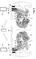
- Fig. 1 shows schematically the structure of a fully implantable hearing system, the output-side actuator stimulation arrangement an electrical, intracochlear Array 10 with a plurality of stimulation electrodes 11 and an electromechanical transducer 14 has, which is here coupled to the anvil 15 as an example.
- the intracochlear stimulus electrode array 10 can be used in any for cochlear implants known manner, for example, be constructed as a unipolar or bipolar arrangement. It has an electrode carrier 12 made of electrically insulating, flexible material on, along which the stimulus electrodes 11 connected to leads 13 in mutual Distance are arranged distributed. The stimulation electrodes 11 are thus in the carrier 12 embedded or fixed to the carrier 12 that a surface portion per stimulus electrode in direct galvanic contact with the lymphatic fluid of the Inner ear or directly to one of the neuronal structures to be irritated.
- the converter 14 can in particular in the manner known from EP-A-0 499 940 be constructed that a housing wall of a hermetically sealed converter housing as vibrating membrane is designed together with one on its inside applied piezoelectric ceramic disc an electromechanically active heteromorph composite element represents and their mechanical vibrations on a the outside of the membrane fixed coupling rod 16 and, if necessary coupling element connected to the coupling rod are transferred to the ossicular chain.
- This converter can do so in the manner explained in DE-C-198 40 211 be modified that a permanent magnet on the inside of the piezoelectric ceramic disc is attached, in the manner of an electromagnetic transducer an electromagnetic coil interacts.
- Such a combined piezoelectric Electromagnetic transducer is especially with regard to a wide frequency band and the achievement of relatively large vibration amplitudes with relatively small ones supplied energy is an advantage.
- the transducer 14 can also be an electromagnetic transducer arrangement act as described in EP-A-0 984 663, that is, one with an am Implantation location with respect to the skull fixable housing and one with reference transducer arrangement movable on the housing and provided with a mechanically rigid coupling element, in which an electromechanical transducer is accommodated in the housing, with which the coupling element can be set in vibration, and that as an electromagnet arrangement is formed, which is a component fixed with respect to the housing as well as an oscillatable component, which with the coupling element in such Connection is that vibrations of the vibratable component on the coupling element be transmitted.
- an electromagnetic transducer arrangement act as described in EP-A-0 984 663, that is, one with an am Implantation location with respect to the skull fixable housing and one with reference transducer arrangement movable on the housing and provided with a mechanically rigid coupling element, in which an electromechanical transducer is accommodated in the housing, with which the coupling element can be set in vibration, and that as an
- a coupling element in addition to a coupling part for the coupling location concerned, a crimp sleeve which initially loosely on a rod-shaped provided with a rough surface Part of a coupling rod is pushed on in the manner previously explained with the Converter is connected.
- the crimp sleeve can be compared to the coupling rod simply be moved and rotated around the coupling part of the coupling element to align exactly with the intended coupling location. Then the The crimp sleeve is fixed by cold-working it plastically using a crimping tool becomes.
- the coupling element can also be used with reference to the coupling rod a retractable belt loop can be set.
- the coupling element has a contact surface at its coupling end, which is adaptable or adapted to the surface shape of the coupling point Surface shape as well as such surface quality and surface size has that by applying the coupling end to the coupling point to a dynamic tension-compression coupling of coupling element and ossicle chain Surface adhesion comes for a secure mutual connection of the coupling element and ossicle chain is sufficient.
- the coupling element can be implanted with one State at the coupling point of the attenuator with entropy-elastic Properties are provided in order to optimize the shape of the stirrup footplate or one the round window or an artificial window in the cochlea, in the Reaching the vestibule or membrane closing in the labyrinth and the risk damage to the natural structures in the area of the coupling point during and to keep it particularly low after implantation (DE 199 35 029).
- the coupling element can according to DE 199 31 788 with an actuator for optional adjustment of the coupling element between an open position, in which the coupling element can be brought into and out of engagement with the coupling point, and one Be provided in the closed position, in which the coupling element in the implanted state is in force and / or positive connection with the coupling point.
- the stirrup footplate or the round window or an artificial window in the cochlea, vestibule or labyrinth (organ of balance) closing membrane is also suitable a coupling arrangement (EP patent application 00 119 019.8) which one of the transducers into mechanical vibrations adjustable coupling rod and one with the pre-selected coupling point in Has connectable coupling element, the coupling rod and the coupling element are connected to each other via at least one coupling and at least a section of the coupling element which bears against the coupling point in the implanted state is designed for low-loss vibration initiation into the coupling point, wherein a first coupling half of the coupling has an outer contour with at least approximately has the shape of a spherical cap, which in one to the outer contour at least partially complementary inner contour of a second coupling half and the coupling is reversibly pivotable against frictional forces.
- such a coupling arrangement has a first Coupling half of the coupling has an outer contour with at least approximately cylindrical, preferably circular cylindrical, shape, in a to the outer contour at least partially complementary inner contour of a second coupling half is, one in contact with the coupling point in the implanted state
- Section of the coupling element for low-loss vibration introduction into the coupling point is designed, in the implanted state a transmission of dynamic Forces between the two coupling halves of the coupling essentially in Direction of the longitudinal axis of the first coupling half takes place, and the coupling reversible coupling and uncoupling as well as reversible linear and / or rotary with reference adjustable on a longitudinal axis of the first coupling half, but in the implanted Dynamic forces occurring are rigid.
- the fully implantable hearing system shown in FIG. 1 also includes an implantable microphone 20, a wireless remote control 21 for controlling the Implant functions through the implant carrier as well as a wireless, transcutaneous charging system with a charger 22 and a charging coil 23 for recharging an im Secondary battery 25 (FIG. 2) for supplying energy to the hearing system.
- an implantable microphone 20 for controlling the Implant functions through the implant carrier as well as a wireless, transcutaneous charging system with a charger 22 and a charging coil 23 for recharging an im Secondary battery 25 (FIG. 2) for supplying energy to the hearing system.
- the microphone 20 can advantageously be constructed in the manner known from EP-A-0 831 673 and with a microphone capsule, which is hermetically sealed on all sides in a housing is, as well as with an electrical bushing arrangement for bushing at least one electrical connection from the interior of the housing to the latter Be provided on the outside, the housing having at least two legs are aligned at an angle with respect to each other, the one leg of the Microphone capsule receives and is provided with a sound inlet membrane, the other leg contains the electrical feedthrough arrangement and opposite the Level of the sound entry membrane is set back, and the geometry of the microphone housing is chosen so that when the microphone is implanted in the mastoid cavity the leg containing the sound entry membrane from the mastoid into an artificial Hole in the back, bony wall of the auditory canal protrudes and the Sound entry membrane touches the skin of the ear canal wall.
- a fixation element from US-A-5 999 632 known type can be provided which has a cuff with a cylindrical housing part encloses the leg containing the sound inlet membrane and with against the side of the ear canal wall facing the ear canal skin projectable, projecting, elastic flange parts is provided.
- Fixation element preferably a bracket, which the flange parts in front the implantation against an elastic restoring force of the flange parts in one Pass through the hole of the wall of the auditory canal Holds position.
- the charging coil 23 connected to the output of the charger 22 preferably forms in the manner known from US-A-5 279 292 part of a transmission series resonant circuit, which is inductively coupled to a receiving series resonance circuit, not shown can be.
- the receiving series resonance circuit can be part of an implantable Electronic module 34 (Fig. 2) and according to US-A-5 279 292 a constant current source form for the battery 25 (Fig. 2).
- the reception series resonance circuit is located here in a battery charging circuit that depends on the particular Phase of the charging current flowing in the charging circuit via one or the other another branch of a full-wave rectifier bridge is closed.
- the electronics module 34 is in the arrangement according to FIG. 1 via a microphone line 35 to the microphone 40, via a transducer feed line 36 to the electromechanical Transducer 14 and an array lead 37 to the intracochlear stimulus electrode array 10 connected.
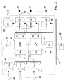
- Fig. 2 shows the possible structure of the signal processing electronics module 34 of the at least partially implantable hearing system.
- Via one or more sound sensors (Microphones) 20 the external sound signal is recorded and converted into electrical Signals converted.
- the analog electrical sensor signals are sent to module 41 passed where it is pre-processed, especially pre-amplified, and converted into digital signals (A / D).
- This preprocessing can take place, for example, in an analog linear or non-linear pre-amplification and filtering (e.g. anti-aliasing filtering) consist.
- the digitized sensor signals are further processed in a digital signal processor 42 (DSP).
- DSP digital signal processor 42
- the signal processor 42 contains a non-rewritable permanent memory area S 0 , in which the instructions and parameters required for "minimal operation" of the system are stored, as well as memory areas Si and S 2 , in which the operating software for the intended function or functions of the implant system are stored.
- the program memories S 1 and S 2 which can be written repeatedly, for accommodating the operating software can be based on EEPROM or static RAM cells, in the latter case it should be ensured that this RAM area is always “buffered" by the implant-internal energy supply system.
- the digital output signals of the signal processor 42 are in digital-to-analog converters (D / A) 43 converted into analog signals and amplified and then the stimulus electrodes 11 and the output-side electromechanical converter 14 supplied.
- D / A digital-to-analog converters
- the signal processor 42 carries out the intended function of the hearing implant. This includes audio signal processing for the rehabilitation of a hearing impairment and possibly also signal generation in the case of a system with additional Tinnitus masker or noiser function.
- the digital signal processor also contains 42 software modules, the dual control of the stimulus electrode array 10 and Make electromechanical converter 14 so that the spectral, temporal, amplitude and phase-related transducer or stimulus electrode signal properties are configured in such a way that the patient's hearing is optimal is achieved.
- These software modules can be designed statically and dynamically his. Static design should be understood to mean that the software modules based on scientific knowledge, once in the program memory of the signal processor 42 are stored and remain unchanged.
- Dynamic means that these software modules are “learnable” in order to achieve the desired to get iteratively as close as possible to optimal hearing success.
- the Software modules can be designed adaptively and the parameter adjustment through “Training” by the implant wearer and possibly other aids, such as rehabilitation programs, is made.
- a software module can also be included be the goal of the best possible hearing care on the basis of a adaptable neural network. Training this neural The mesh can again through the implant carrier and / or with the help of other external aids.
- the system according to FIG. 2 contains a further microprocessor module, for example a microcontroller ( ⁇ C) 44 with associated memories S 3 , S 4 and S 5 .
- the memory S 3 is a repeatedly writable memory in which a work program for the microcontroller 44 is stored.
- the operating software components of the implant management system can be stored in the memory areas S 4 and S 5 (for example administrative monitoring and telemetry functions).
- patient-specific, for example audiological adaptation parameters, which are changeable from the outside can also be stored.
- the microcontroller 44 communicates on the one hand via a bidirectional data bus 45 and a telemetry system (TS) 46 wirelessly (for example by means of inductive coupling) through the closed skin indicated at 47 with an external programming system (PS) 48.
- the programming system 48 can also be a PC-based system appropriate programming, editing, presentation and management software.
- the operating software of the implant system that is to be changed or completely replaced is transmitted via this telemetry interface and initially stored temporarily in the memory area S 4 and / or S 5 of the microcontroller 44.
- a simple verification of the software transmission can be carried out by a reading process via the telemetry interface before the operating software or the corresponding signal processing parts of this software are transmitted to the program memory areas S 1 and S 2 of the digital signal processor 42 via a data bus 50.
- the work program for the microcontroller 44 can also be changed or exchanged in whole or in part using the external unit 48 via the telemetry interface.
- the microcontroller 44 controls intra-implant via the bidirectional Data bus 50, the A / D converter 41 of the sensor preprocessing, the D / A converter 43 for Control of the stimulus electrodes 11 and the electromechanical transducer 14 and Signal processor 42 itself.
- the D / A converter 43 can also be omitted in whole or in part, if digitally controlled current sources are provided for the stimulation electrodes and / or when using an electromagnetic output transducer 14 for example pulse width modulated, serial digital output signal of the signal processor 42 is transmitted directly to the converter 14.
- Be over the data bus 50 also program parts or entire software modules between the outside world, microcontrollers 44 and signal processor 42 transmitted.
- the implant system also contains the primary one or secondary battery cell 25, which the individual modules with electrical operating energy supplied and conveniently combined with the electronics module 34 is.
- FIG. 3 shows a binaural application of a hearing implant according to FIG. 1.
- transcutaneous charging devices 22, 23 are also here for the case of implant-side secondary energy storage elements (batteries 25) and a wireless remote control that controls both electronic modules 34 synchronously 21 for use by the implant carrier.
- FIG. 4 shows the binaural application of a hearing implant according to FIG. 1, in which the Signal processing modules 34 over a wireless connection (for example one at 53 indicated bidirectional radio-frequency link) communicate with each other that optimal binaural signal processing and transducer or stimulation electrode array control is achieved in both implanted ears.
- a wireless connection for example one at 53 indicated bidirectional radio-frequency link
- transcutaneous loading devices 22, 23 for the case implant-side secondary energy storage elements (batteries 25) provided as well a wireless remote control 21 for use by the implant carrier, both of which Controls electronics modules 34 synchronously.
- the binaural design of the hearing implant according to FIG. 5 differs from that 4 only in that for wireless communication between the Signal processing modules 34 of both system units a structure-borne noise Ultrasonic path 54 with ultrasonic couplers 55 is provided.
- the ultrasonic couplers 55 can 5, from the electronics module 34 locally separated and via electrical Lines connected ultrasound receivers and transmitters, which are preferred are firmly coupled to the skull in the mastoid area.
- the ultrasonic coupler can also be integrated in the electronic modules 34 (not shown), if the electronic modules are implanted in the mastoid area so that a Ultrasound body transmission through the skull can take place.
- FIG. 6 A further modified embodiment of a binaural hearing implant is shown in Fig. 6.
- bidirectional Information on the implant side is preferably amplitude or frequency modulated onto a carrier and applied to implanted electrodes 56, which are part of a body tissue of the implant carrier leading data transmission path 57. It will receive a modulated tissue flow which is known in a manner known per se (DE-A 38 31 809) for the desired communication between the signal processing modules 34 of both system units.
- FIG. 7 schematically shows the structure of a monaural partially implantable hearing system intracochlear stimulus electrode array 10 and electromechanical transducer 14 according to Fig. 1.
- this partially implantable system are a microphone 20, an electronic module 62 for electronic signal processing largely as shown in FIG. 2 (but without the telemetry system 46), the energy supply (battery) 25 and one Modulator / transmitter unit 63 in an externally on the body, preferably on the head above the implant, external module 64 to be carried.
- the implant is like with known partial implants energetically passive.
- His electronics module 34 (without battery 52) receives operating energy and converter or stimulation electrode control data 10 via the modulator / transmitter unit 63 in the external part 64.
Landscapes
- Health & Medical Sciences (AREA)
- Otolaryngology (AREA)
- Engineering & Computer Science (AREA)
- Biomedical Technology (AREA)
- Nuclear Medicine, Radiotherapy & Molecular Imaging (AREA)
- Radiology & Medical Imaging (AREA)
- Life Sciences & Earth Sciences (AREA)
- Animal Behavior & Ethology (AREA)
- General Health & Medical Sciences (AREA)
- Public Health (AREA)
- Veterinary Medicine (AREA)
- Prostheses (AREA)
- Rehabilitation Tools (AREA)
- Electrotherapy Devices (AREA)
Applications Claiming Priority (2)
| Application Number | Priority Date | Filing Date | Title |
|---|---|---|---|
| DE10018334A DE10018334C1 (de) | 2000-04-13 | 2000-04-13 | Mindestens teilimplantierbares System zur Rehabilitation einer Hörstörung |
| DE10018334 | 2000-04-13 |
Publications (3)
| Publication Number | Publication Date |
|---|---|
| EP1145734A2 true EP1145734A2 (fr) | 2001-10-17 |
| EP1145734A3 EP1145734A3 (fr) | 2004-02-25 |
| EP1145734B1 EP1145734B1 (fr) | 2005-11-23 |
Family
ID=7638612
Family Applications (1)
| Application Number | Title | Priority Date | Filing Date |
|---|---|---|---|
| EP01109192A Expired - Lifetime EP1145734B1 (fr) | 2000-04-13 | 2001-04-12 | Système au moins partiellement implantable de réhabilitation d'un trouble auditif |
Country Status (6)
| Country | Link |
|---|---|
| US (2) | US6697674B2 (fr) |
| EP (1) | EP1145734B1 (fr) |
| AT (1) | ATE310565T1 (fr) |
| AU (1) | AU784113B2 (fr) |
| CA (1) | CA2343690A1 (fr) |
| DE (2) | DE10018334C1 (fr) |
Cited By (2)
| Publication number | Priority date | Publication date | Assignee | Title |
|---|---|---|---|---|
| DE102007059748A1 (de) | 2007-12-07 | 2009-06-18 | Universität Rostock | Positionierungsvorrichtung für aktive Innenohrimplantate |
| WO2010151768A1 (fr) * | 2009-06-26 | 2010-12-29 | Med-El Elektromedizinische Geraete Gmbh | Système d'introduction d'un support d'électrode implantable |
Families Citing this family (188)
| Publication number | Priority date | Publication date | Assignee | Title |
|---|---|---|---|---|
| US7787647B2 (en) | 1997-01-13 | 2010-08-31 | Micro Ear Technology, Inc. | Portable system for programming hearing aids |
| US20030036746A1 (en) | 2001-08-16 | 2003-02-20 | Avi Penner | Devices for intrabody delivery of molecules and systems and methods utilizing same |
| US8260430B2 (en) | 2010-07-01 | 2012-09-04 | Cochlear Limited | Stimulation channel selection for a stimulating medical device |
| US6904402B1 (en) * | 1999-11-05 | 2005-06-07 | Microsoft Corporation | System and iterative method for lexicon, segmentation and language model joint optimization |
| AU2001229591A1 (en) * | 2000-01-20 | 2001-07-31 | Starkey Laboratories, Inc. | Hearing aid systems |
| DE10018334C1 (de) * | 2000-04-13 | 2002-02-28 | Implex Hear Tech Ag | Mindestens teilimplantierbares System zur Rehabilitation einer Hörstörung |
| AU2001261344A1 (en) * | 2000-05-10 | 2001-11-20 | The Board Of Trustees Of The University Of Illinois | Interference suppression techniques |
| US9008786B2 (en) * | 2000-08-21 | 2015-04-14 | Cochlear Limited | Determining stimulation signals for neural stimulation |
| AUPQ952800A0 (en) * | 2000-08-21 | 2000-09-14 | Cochlear Limited | Power efficient electrical stimulation |
| US8285382B2 (en) * | 2000-08-21 | 2012-10-09 | Cochlear Limited | Determining stimulation signals for neural stimulation |
| US7822478B2 (en) * | 2000-08-21 | 2010-10-26 | Cochlear Limited | Compressed neural coding |
| CA2442899A1 (fr) * | 2001-04-06 | 2002-10-17 | Cochlear Limited | Electrode endo-osseuse |
| US7962226B2 (en) * | 2001-04-06 | 2011-06-14 | Cochlear Limited | Cochlear endosteal electrode carrier member |
| WO2002082982A1 (fr) * | 2001-04-18 | 2002-10-24 | Cochlear Limited | Procede et appareil de mesure de reponses neuronales evoquees |
| SE523100C2 (sv) * | 2001-06-21 | 2004-03-30 | P & B Res Ab | Benförankrad hörapparat avsedd för överledning av ljud |
| AUPR604801A0 (en) * | 2001-06-29 | 2001-07-26 | Cochlear Limited | Multi-electrode cochlear implant system with distributed electronics |
| US10576275B2 (en) | 2001-07-06 | 2020-03-03 | Cochlear Limited | System and method for configuring an external device using operating parameters from an implanted device |
| US7292891B2 (en) * | 2001-08-20 | 2007-11-06 | Advanced Bionics Corporation | BioNet for bilateral cochlear implant systems |
| US20070088335A1 (en) * | 2001-10-24 | 2007-04-19 | Med-El Elektromedizinische Geraete Gmbh | Implantable neuro-stimulation electrode with fluid reservoir |
| JP4398728B2 (ja) | 2001-10-24 | 2010-01-13 | メド−エル・エレクトロメディツィニシェ・ゲラーテ・ゲーエムベーハー | 埋込み式流体配送装置と埋込み式電極 |
| US20100030130A1 (en) * | 2001-11-09 | 2010-02-04 | Cochlear Limited | Pharmaceutical intervention for modulation of neural plasticity |
| AUPS101502A0 (en) * | 2002-03-11 | 2002-04-11 | Neopraxis Pty Ltd | Wireless fes system |
| AUPS318202A0 (en) * | 2002-06-26 | 2002-07-18 | Cochlear Limited | Parametric fitting of a cochlear implant |
| AUPS322702A0 (en) * | 2002-06-28 | 2002-07-18 | Cochlear Limited | Cochlear implant electrode array |
| AU2002950754A0 (en) | 2002-08-09 | 2002-09-12 | Cochlear Limited | Mechanical design for a cochlear implant |
| AU2002950755A0 (en) * | 2002-08-09 | 2002-09-12 | Cochlear Limited | Fixation system for a cochlear implant |
| US7974700B1 (en) * | 2002-08-09 | 2011-07-05 | Cochlear Limited | Cochlear implant component having a unitary faceplate |
| AU2002951218A0 (en) * | 2002-09-04 | 2002-09-19 | Cochlear Limited | Method and apparatus for measurement of evoked neural response |
| WO2004024212A2 (fr) * | 2002-09-10 | 2004-03-25 | Vibrant Med-El Hearing Technology Gmbh | Dispositifs medicaux implantables a plusieurs transducteurs |
| US7512448B2 (en) * | 2003-01-10 | 2009-03-31 | Phonak Ag | Electrode placement for wireless intrabody communication between components of a hearing system |
| US8355794B2 (en) * | 2003-03-11 | 2013-01-15 | Cochlear Limited | Using a genetic algorithm in mixed mode device |
| US6879860B2 (en) * | 2003-03-11 | 2005-04-12 | Gregory Howard Wakefield | Cochlear implant MAP optimization with use of a genetic algorithm |
| US8255059B2 (en) | 2003-03-11 | 2012-08-28 | Cochlear Limited | Using a genetic algorithm to fit a medical implant system to a patient |
| AU2003901852A0 (en) * | 2003-04-16 | 2003-05-01 | Cochlear Limited | Cochlear electrode array |
| AU2003901867A0 (en) | 2003-04-17 | 2003-05-08 | Cochlear Limited | Osseointegration fixation system for an implant |
| US8811643B2 (en) | 2003-05-08 | 2014-08-19 | Advanced Bionics | Integrated cochlear implant headpiece |
| AU2003903576A0 (en) * | 2003-07-11 | 2003-07-24 | Cochlear Limited | Audio path diagnostics |
| AU2003903579A0 (en) * | 2003-07-11 | 2003-07-24 | Cochlear Limited | Three wire headset |
| AU2003904085A0 (en) * | 2003-08-04 | 2003-08-21 | Cochlear Limited | Magnetic on/off switch for speech processor |
| AU2003904139A0 (en) * | 2003-08-07 | 2003-08-21 | Cochlear Limited | Miniature switches |
| US20070213787A1 (en) * | 2003-09-05 | 2007-09-13 | Kuzma Janusz A | Soft, middle-ear electrode for suppressing tinnitis |
| US20070213788A1 (en) * | 2003-09-19 | 2007-09-13 | Osberger Mary J | Electrical stimulation of the inner ear in patients with unilateral hearing loss |
| US20050102006A1 (en) * | 2003-09-25 | 2005-05-12 | Whitehurst Todd K. | Skull-mounted electrical stimulation system |
| US20070282395A1 (en) * | 2003-10-06 | 2007-12-06 | Maltan Albert A | System and method for preserving neuronal survival and plasticity of the auditory system prior to permanent intra-cochlear implantation |
| US20070282396A1 (en) * | 2003-10-14 | 2007-12-06 | Overstreet Edward H | System and method of contra-lateral ear stimulation for preserving neuronal survival and plasticity of the auditory system prior to permanent intra-cochlear implantation |
| SE527006C2 (sv) * | 2003-10-22 | 2005-12-06 | Entific Medical Systems Ab | Anordning för att bota eller minska stamning |
| US9380980B2 (en) * | 2004-03-05 | 2016-07-05 | Depuy International Limited | Orthpaedic monitoring system, methods and apparatus |
| US7651460B2 (en) * | 2004-03-22 | 2010-01-26 | The Board Of Regents Of The University Of Oklahoma | Totally implantable hearing system |
| US7561920B2 (en) * | 2004-04-02 | 2009-07-14 | Advanced Bionics, Llc | Electric and acoustic stimulation fitting systems and methods |
| US7630772B1 (en) | 2004-05-05 | 2009-12-08 | Advanced Bionics, Llc | Methods of converting a behind-the-ear speech processor unit into a body worn speech processor unit |
| US8660658B2 (en) | 2004-05-05 | 2014-02-25 | Advanced Bionics Ag | Speech processor cases |
| US8244365B2 (en) * | 2004-05-10 | 2012-08-14 | Cochlear Limited | Simultaneous delivery of electrical and acoustical stimulation in a hearing prosthesis |
| US20060093997A1 (en) * | 2004-06-12 | 2006-05-04 | Neurotone, Inc. | Aural rehabilitation system and a method of using the same |
| WO2005124722A2 (fr) * | 2004-06-12 | 2005-12-29 | Spl Development, Inc. | Systeme de reeducation auditive et son procede d'utilisation |
| US7801617B2 (en) | 2005-10-31 | 2010-09-21 | Cochlear Limited | Automatic measurement of neural response concurrent with psychophysics measurement of stimulating device recipient |
| CA2569724A1 (fr) * | 2004-06-15 | 2005-12-29 | Cochlear Americas | Determination automatique du seuil d'une reponse neuronale evoquee |
| US8190268B2 (en) * | 2004-06-15 | 2012-05-29 | Cochlear Limited | Automatic measurement of an evoked neural response concurrent with an indication of a psychophysics reaction |
| US7711133B2 (en) * | 2004-06-28 | 2010-05-04 | Hearworks Pty Limited | Selective resolution speech processing |
| US7489967B2 (en) * | 2004-07-09 | 2009-02-10 | Cardiac Pacemakers, Inc. | Method and apparatus of acoustic communication for implantable medical device |
| US8401212B2 (en) | 2007-10-12 | 2013-03-19 | Earlens Corporation | Multifunction system and method for integrated hearing and communication with noise cancellation and feedback management |
| US20060025833A1 (en) * | 2004-07-29 | 2006-02-02 | Cochlear Limited | Variable width electrode scheme |
| US7421298B2 (en) * | 2004-09-07 | 2008-09-02 | Cochlear Limited | Multiple channel-electrode mapping |
| US20060085051A1 (en) * | 2004-10-19 | 2006-04-20 | Fritsch Michael H | Electrical implants |
| JP5121011B2 (ja) * | 2004-11-24 | 2013-01-16 | レモン メディカル テクノロジーズ リミテッド | 音響トランスデューサを組み込んだインプラント可能な医療機器 |
| US7522962B1 (en) | 2004-12-03 | 2009-04-21 | Remon Medical Technologies, Ltd | Implantable medical device with integrated acoustic transducer |
| WO2006062545A2 (fr) * | 2004-12-07 | 2006-06-15 | Auragin, Inc. | Implant auditif cochleaire |
| US8170677B2 (en) * | 2005-04-13 | 2012-05-01 | Cochlear Limited | Recording and retrieval of sound data in a hearing prosthesis |
| DE102005017493A1 (de) | 2005-04-15 | 2006-10-19 | Siemens Audiologische Technik Gmbh | Hörhilfevorrichtung mit zwei unterschiedlichen Ausgangswandlern und Anpassverfahren |
| AU2006242390A1 (en) * | 2005-04-29 | 2006-11-09 | Cochlear Americas | Focused stimulation in a medical stimulation device |
| CN100346755C (zh) * | 2005-06-24 | 2007-11-07 | 清华大学 | 带有片上信号处理器的双向多通道人工耳蜗系统 |
| CN100394903C (zh) * | 2005-06-24 | 2008-06-18 | 清华大学 | 双向数字调制多通道人工耳蜗系统 |
| US20090222064A1 (en) * | 2005-07-08 | 2009-09-03 | Advanced Bionics, Llc | Autonomous Autoprogram Cochlear Implant |
| US8285383B2 (en) * | 2005-07-08 | 2012-10-09 | Cochlear Limited | Directional sound processing in a cochlear implant |
| US7570998B2 (en) * | 2005-08-26 | 2009-08-04 | Cardiac Pacemakers, Inc. | Acoustic communication transducer in implantable medical device header |
| US7615012B2 (en) * | 2005-08-26 | 2009-11-10 | Cardiac Pacemakers, Inc. | Broadband acoustic sensor for an implantable medical device |
| WO2007053882A1 (fr) * | 2005-11-10 | 2007-05-18 | Cochlear Limited | Arrangement pour la fixation d'un appareil médical implantable |
| US20070162098A1 (en) * | 2005-12-08 | 2007-07-12 | Cochlear Limited | Prosthetic hearing implant electrode assembly having optimal length for atraumatic implantation |
| US8265765B2 (en) * | 2005-12-08 | 2012-09-11 | Cochlear Limited | Multimodal auditory fitting |
| US7937154B2 (en) | 2005-12-08 | 2011-05-03 | Cochlear Limited | Promoting curvature and maintaining orientation of an electrode carrier member of a stimulating medical device |
| US20080154339A1 (en) | 2006-12-21 | 2008-06-26 | Cochlear Limited | Electrically Nonconductive Occludent For Tissue Openings |
| US7670278B2 (en) * | 2006-01-02 | 2010-03-02 | Oticon A/S | Hearing aid system |
| US8014871B2 (en) | 2006-01-09 | 2011-09-06 | Cochlear Limited | Implantable interferometer microphone |
| USRE49527E1 (en) | 2006-02-10 | 2023-05-16 | Cochlear Limited | Recognition of implantable medical device |
| AR059786A1 (es) * | 2006-03-09 | 2008-04-30 | Med El Elektromed Geraete Gmbh | Configuracion de electrodo de implante coclear para eluir farmacos |
| US8571675B2 (en) * | 2006-04-21 | 2013-10-29 | Cochlear Limited | Determining operating parameters for a stimulating medical device |
| US8818517B2 (en) | 2006-05-05 | 2014-08-26 | Advanced Bionics Ag | Information processing and storage in a cochlear stimulation system |
| US7526337B2 (en) * | 2006-06-06 | 2009-04-28 | Cardiac Pacemakers, Inc. | Method and device for lymphatic system monitoring |
| US7734341B2 (en) * | 2006-06-06 | 2010-06-08 | Cardiac Pacemakers, Inc. | Method and apparatus for gastrointestinal stimulation via the lymphatic system |
| US7894906B2 (en) * | 2006-06-06 | 2011-02-22 | Cardiac Pacemakers, Inc. | Amelioration of chronic pain by endolymphatic stimulation |
| US8126538B2 (en) * | 2006-06-06 | 2012-02-28 | Cardiac Pacemakers, Inc. | Method and apparatus for introducing endolymphatic instrumentation |
| US20070282376A1 (en) | 2006-06-06 | 2007-12-06 | Shuros Allan C | Method and apparatus for neural stimulation via the lymphatic system |
| EP2609959A1 (fr) * | 2006-06-13 | 2013-07-03 | Med-El Elektromedizinische Geräte GmbH | Système d'alimentation d'implant cochléaire et méthodologie |
| US7912548B2 (en) * | 2006-07-21 | 2011-03-22 | Cardiac Pacemakers, Inc. | Resonant structures for implantable devices |
| US7764798B1 (en) * | 2006-07-21 | 2010-07-27 | Cingular Wireless Ii, Llc | Radio frequency interference reduction in connection with mobile phones |
| JP2009544366A (ja) * | 2006-07-21 | 2009-12-17 | カーディアック ペースメイカーズ, インコーポレイテッド | 金属製キャビティが植え込まれた医療器具に用いる超音波トランスデューサ |
| US8905999B2 (en) | 2006-09-01 | 2014-12-09 | Cardiac Pacemakers, Inc. | Method and apparatus for endolymphatic drug delivery |
| CA2601662A1 (fr) | 2006-09-18 | 2008-03-18 | Matthias Mullenborn | Interface sans fil pour programmer des dispositifs d'aide auditive |
| US9037244B2 (en) * | 2007-02-13 | 2015-05-19 | Virender K. Sharma | Method and apparatus for electrical stimulation of the pancreatico-biliary system |
| US9402990B2 (en) * | 2007-03-20 | 2016-08-02 | Cochlear Limited | Securing an implanted medical device in a patient |
| US8718795B2 (en) * | 2007-03-20 | 2014-05-06 | Cochlear Limited | Securing an implanted medical device in a patient |
| US8825161B1 (en) | 2007-05-17 | 2014-09-02 | Cardiac Pacemakers, Inc. | Acoustic transducer for an implantable medical device |
| EP2162185B1 (fr) * | 2007-06-14 | 2015-07-01 | Cardiac Pacemakers, Inc. | Système de recharge acoustique à plusieurs éléments |
| EP2227914A1 (fr) * | 2007-10-30 | 2010-09-15 | 3Win N.V. | Module de transducteur sans fil à porter sur le corps |
| WO2009076721A1 (fr) * | 2007-12-18 | 2009-06-25 | Cochlear Limited | Procédé et système d'ajustage d'un implant cochléaire |
| EP2082779A3 (fr) | 2008-01-22 | 2014-02-19 | Cochlear Limited | Adaptation contrôlée par le porteur d'une prothèse auditive |
| US9179226B2 (en) * | 2008-02-07 | 2015-11-03 | Advanced Bionics Ag | Partially implantable hearing device |
| US9889307B2 (en) * | 2008-02-22 | 2018-02-13 | Cochlear Limited | Interleaving power and data in a transcutaneous communications link |
| US20090306458A1 (en) * | 2008-03-31 | 2009-12-10 | Cochlear Limited | Direct acoustic cochlear stimulator for round window access |
| US20100010569A1 (en) * | 2008-03-31 | 2010-01-14 | Cochlear Limited | Mechanical semicircular canal stimulator |
| US20090287277A1 (en) * | 2008-05-19 | 2009-11-19 | Otologics, Llc | Implantable neurostimulation electrode interface |
| WO2009155358A1 (fr) | 2008-06-17 | 2009-12-23 | Earlens Corporation | Dispositifs d’audition électromécaniques optiques dotés de composants d’alimentation et de signal séparés |
| US20100069997A1 (en) * | 2008-09-16 | 2010-03-18 | Otologics, Llc | Neurostimulation apparatus |
| EP3509324B1 (fr) | 2008-09-22 | 2023-08-16 | Earlens Corporation | Dispositifs à armature équilibrée et procédés d'écoute |
| US10603489B2 (en) | 2008-10-09 | 2020-03-31 | Virender K. Sharma | Methods and apparatuses for stimulating blood vessels in order to control, treat, and/or prevent a hemorrhage |
| US9079028B2 (en) | 2008-10-09 | 2015-07-14 | Virender K. Sharma | Method and apparatus for stimulating the vascular system |
| EP2337607B1 (fr) * | 2008-10-15 | 2018-06-13 | Med-El Elektromedizinische Geräte GmbH | Dispositif d administration de médicaments dans l oreille interne |
| WO2010054308A1 (fr) | 2008-11-10 | 2010-05-14 | Med-El Elektromedizinische Geraete Gmbh | Réservoirs d’administration de médicaments remplis d’hydrogel |
| WO2010081201A1 (fr) | 2009-01-19 | 2010-07-22 | Cochlear Limited | Modification de surface pour dispositif médical implantable |
| US8954158B2 (en) * | 2009-02-05 | 2015-02-10 | Cochlear Limited | Multi-electrode channel configurations |
| US9044588B2 (en) * | 2009-04-16 | 2015-06-02 | Cochlear Limited | Reference electrode apparatus and method for neurostimulation implants |
| RU2573184C2 (ru) * | 2009-05-15 | 2016-01-20 | Конинклейке Филипс Электроникс Н.В. | Имплантируемое устройство со средствами связи |
| US8771166B2 (en) | 2009-05-29 | 2014-07-08 | Cochlear Limited | Implantable auditory stimulation system and method with offset implanted microphones |
| US8774930B2 (en) * | 2009-07-22 | 2014-07-08 | Vibrant Med-El Hearing Technology Gmbh | Electromagnetic bone conduction hearing device |
| DE102009035386B4 (de) | 2009-07-30 | 2011-12-15 | Cochlear Ltd. | Hörhilfeimplantat |
| US20110060385A1 (en) * | 2009-09-10 | 2011-03-10 | Lineaweaver Sean K | Determining stimulation level parameters in implant fitting |
| US8401978B2 (en) | 2009-09-10 | 2013-03-19 | Cochlear Limited | Using a genetic algorithm employing an expedited convergence mechanism to at least partially fit a medical implant to a patient using patient feedback |
| US8825168B2 (en) * | 2009-09-10 | 2014-09-02 | Cochlear Limited | Using a genetic algorithm employing dynamic mutation |
| US20110060384A1 (en) * | 2009-09-10 | 2011-03-10 | Cochlear Limited | Determining stimulation level parameters in implant fitting |
| EP2475420B1 (fr) * | 2009-09-11 | 2015-09-02 | MED-EL Elektromedizinische Geräte GmbH | Stimulation d'implant cochléaire avec faible taux d'impulsions, conjointement avec une représentation séparée de fréquences fondamentales et de distinctions voisées/non voisées |
| AU2009222439B2 (en) * | 2009-09-28 | 2011-07-21 | Cochlear Limited | Method and circuitry for measurement and control of stimulation current |
| US8594806B2 (en) | 2010-04-30 | 2013-11-26 | Cyberonics, Inc. | Recharging and communication lead for an implantable device |
| US8625828B2 (en) * | 2010-04-30 | 2014-01-07 | Cochlear Limited | Hearing prosthesis having an on-board fitting system |
| US9031661B2 (en) | 2010-05-18 | 2015-05-12 | Cochlear Limited | Multi-electrode channel configurations for a hearing prosthesis |
| EP2601797A1 (fr) * | 2010-08-03 | 2013-06-12 | Advanced Bionics AG | Prothèse auditive rechargeable partiellement implantable |
| US9155886B2 (en) | 2010-10-28 | 2015-10-13 | Cochlear Limited | Fitting an auditory prosthesis |
| US8657759B2 (en) | 2010-11-08 | 2014-02-25 | Cochlear Limited | Compartmentalized implant fitting software |
| US20120136197A1 (en) * | 2010-11-30 | 2012-05-31 | Van Gerwen Peter B J | Hearing prosthesis having a flexible elongate energy transfer mechanism |
| EP2651493B1 (fr) * | 2010-12-16 | 2019-04-10 | Advanced Bionics AG | Contrôle de volume indépendant dans des systèmes de stimulation électro-acoustique |
| EP3758394A1 (fr) | 2010-12-20 | 2020-12-30 | Earlens Corporation | Appareil auditif intra-auriculaire anatomiquement personnalisé |
| US9352153B2 (en) | 2011-01-24 | 2016-05-31 | Cochlear Limited | Systems and methods for detecting nerve stimulation with an implanted prosthesis |
| US9272142B2 (en) | 2011-01-28 | 2016-03-01 | Cochlear Limited | Systems and methods for using a simplified user interface for hearing prosthesis fitting |
| US8515540B2 (en) | 2011-02-24 | 2013-08-20 | Cochlear Limited | Feedthrough having a non-linear conductor |
| US10418047B2 (en) | 2011-03-14 | 2019-09-17 | Cochlear Limited | Sound processing with increased noise suppression |
| US10419861B2 (en) | 2011-05-24 | 2019-09-17 | Cochlear Limited | Convertibility of a bone conduction device |
| US9313589B2 (en) | 2011-07-01 | 2016-04-12 | Cochlear Limited | Method and system for configuration of a medical device that stimulates a human physiological system |
| US20130096366A1 (en) | 2011-10-12 | 2013-04-18 | Wim Bervoets | Implantable medical device |
| WO2014030159A1 (fr) * | 2012-08-20 | 2014-02-27 | Mizur Technology Ltd. | Dispositif de correction auditive |
| US9343923B2 (en) | 2012-08-23 | 2016-05-17 | Cyberonics, Inc. | Implantable medical device with backscatter signal based communication |
| US9049527B2 (en) | 2012-08-28 | 2015-06-02 | Cochlear Limited | Removable attachment of a passive transcutaneous bone conduction device with limited skin deformation |
| US9935498B2 (en) | 2012-09-25 | 2018-04-03 | Cyberonics, Inc. | Communication efficiency with an implantable medical device using a circulator and a backscatter signal |
| USD693008S1 (en) | 2013-03-09 | 2013-11-05 | Advanced Bionics Ag | Sound processor enclosure exterior |
| EP3441109A1 (fr) | 2013-05-30 | 2019-02-13 | Graham H. Creasey | Timbre dermique souple pour système de neurostimuleur topique |
| US11229789B2 (en) | 2013-05-30 | 2022-01-25 | Neurostim Oab, Inc. | Neuro activator with controller |
| US12311114B2 (en) | 2013-08-30 | 2025-05-27 | Neuromod Devices Limited | Method and apparatus for treating a neurological disorder |
| EP2842530B1 (fr) * | 2013-08-30 | 2021-09-29 | Neuromod Devices Limited | Procédé et système de génération d'un stimulus sensoriel personnalisé |
| US9968781B2 (en) * | 2014-03-12 | 2018-05-15 | Advanced Bionics Ag | Implantable hearing assistance apparatus and corresponding systems and methods |
| US10034103B2 (en) | 2014-03-18 | 2018-07-24 | Earlens Corporation | High fidelity and reduced feedback contact hearing apparatus and methods |
| EP3122421B1 (fr) | 2014-03-22 | 2019-08-07 | Advanced Bionics AG | Systèmes d'aide auditive sans accessoire porté sur la tête |
| WO2015147773A1 (fr) | 2014-03-22 | 2015-10-01 | Advanced Bionics Ag | Appareil auditif implantable et systèmes et procédés correspondants |
| DK3169396T3 (da) | 2014-07-14 | 2021-06-28 | Earlens Corp | Glidende forspænding og peak-begrænsning for optiske høreapparater |
| US9924276B2 (en) | 2014-11-26 | 2018-03-20 | Earlens Corporation | Adjustable venting for hearing instruments |
| US10525265B2 (en) * | 2014-12-09 | 2020-01-07 | Cochlear Limited | Impulse noise management |
| US10105539B2 (en) | 2014-12-17 | 2018-10-23 | Cochlear Limited | Configuring a stimulation unit of a hearing device |
| US11077301B2 (en) | 2015-02-21 | 2021-08-03 | NeurostimOAB, Inc. | Topical nerve stimulator and sensor for bladder control |
| TWI580279B (zh) * | 2015-05-14 | 2017-04-21 | 陳光超 | 耳膜掛持之耳蝸助聽器 |
| TWI609589B (zh) * | 2015-05-14 | 2017-12-21 | 陳光超 | 聽覺輔助裝置與聽覺輔助運作方法 |
| DK3888564T3 (da) * | 2015-10-02 | 2025-07-14 | Earlens Corp | Indretning til tilpasset afgivelse af medicin i øregangen |
| US10321247B2 (en) | 2015-11-27 | 2019-06-11 | Cochlear Limited | External component with inductance and mechanical vibratory functionality |
| US11350226B2 (en) | 2015-12-30 | 2022-05-31 | Earlens Corporation | Charging protocol for rechargeable hearing systems |
| US10492010B2 (en) | 2015-12-30 | 2019-11-26 | Earlens Corporations | Damping in contact hearing systems |
| WO2017116791A1 (fr) | 2015-12-30 | 2017-07-06 | Earlens Corporation | Systèmes, appareil et procédés auditifs reposant sur la lumière |
| US10560791B2 (en) * | 2016-01-29 | 2020-02-11 | Cochlear Limited | Hybrid electrically- and mechanically-stimulating cochlear implant |
| US11071869B2 (en) | 2016-02-24 | 2021-07-27 | Cochlear Limited | Implantable device having removable portion |
| US10602284B2 (en) | 2016-07-18 | 2020-03-24 | Cochlear Limited | Transducer management |
| US10238871B2 (en) * | 2016-08-02 | 2019-03-26 | Cochlear Limited | Implantable medical device arrangements |
| CN112738700A (zh) | 2016-09-09 | 2021-04-30 | 伊尔兰斯公司 | 智能镜系统和方法 |
| US10085097B2 (en) * | 2016-10-04 | 2018-09-25 | Starkey Laboratories, Inc. | Hearing assistance device incorporating system in package module |
| WO2018093733A1 (fr) | 2016-11-15 | 2018-05-24 | Earlens Corporation | Procédure d'impression améliorée |
| CN109952062B (zh) * | 2016-11-15 | 2022-05-10 | 皇家飞利浦有限公司 | 超声设备接触 |
| US10525271B2 (en) | 2017-08-16 | 2020-01-07 | Cochlear Limited | Charging-induced implant operation |
| WO2019094365A1 (fr) | 2017-11-07 | 2019-05-16 | Neurostim Oab, Inc. | Activateur de nerf non invasif à circuit adaptatif |
| WO2019173470A1 (fr) | 2018-03-07 | 2019-09-12 | Earlens Corporation | Dispositif auditif de contact et matériaux de structure de rétention |
| WO2019199680A1 (fr) | 2018-04-09 | 2019-10-17 | Earlens Corporation | Filtre dynamique |
| KR102194266B1 (ko) * | 2018-08-20 | 2020-12-22 | (주)모비프렌 | Tens 치료 기능을 가지는 골전도 장치 |
| CA3144957A1 (fr) | 2019-06-26 | 2020-12-30 | Neurostim Technologies Llc | Activateur de nerf non invasif a circuit adaptatif |
| EP4021563B1 (fr) | 2019-08-29 | 2024-12-04 | Cochlear Limited | Support implantable avec stabilisateur intégré |
| WO2021126921A1 (fr) | 2019-12-16 | 2021-06-24 | Neurostim Solutions, Llc | Activateur nerveux non invasif à distribution de charge amplifiée |
| WO2025149997A1 (fr) * | 2024-01-14 | 2025-07-17 | Cochlear Limited | Techniques de prise en charge des acouphènes |
Citations (7)
| Publication number | Priority date | Publication date | Assignee | Title |
|---|---|---|---|---|
| US4441210A (en) | 1981-09-18 | 1984-04-03 | Hochmair Erwin S | Transcutaneous signal transmission system and methods |
| EP0200321A2 (fr) | 1985-03-20 | 1986-11-05 | Ingeborg J. Hochmair | Système de transmission de signal transdermique |
| US5545219A (en) | 1995-03-30 | 1996-08-13 | Cochlear, Ltd. | Cochlear electrode implant assemblies with positioning system therefor |
| US5578084A (en) | 1991-09-27 | 1996-11-26 | Cochlear Ltd. | Self-curving cochlear electrode array |
| US5626629A (en) | 1995-05-31 | 1997-05-06 | Advanced Bionics Corporation | Programming of a speech processor for an implantable cochlear stimulator |
| US5800475A (en) | 1995-05-31 | 1998-09-01 | Bertin & Cie | Hearing aid including a cochlear implant |
| US5957958A (en) | 1997-01-15 | 1999-09-28 | Advanced Bionics Corporation | Implantable electrode arrays |
Family Cites Families (71)
| Publication number | Priority date | Publication date | Assignee | Title |
|---|---|---|---|---|
| US923469A (en) * | 1907-08-10 | 1909-06-01 | Oscar Wiederhold | Inverted incandescent gas-lamp. |
| US3557775A (en) | 1963-12-27 | 1971-01-26 | Jack Lawrence Mahoney | Method of implanting a hearing aid |
| US3715962A (en) * | 1970-04-20 | 1973-02-13 | Spectral Data Corp | Spectral-zonal color reconnaissance system |
| US3712962A (en) | 1971-04-05 | 1973-01-23 | J Epley | Implantable piezoelectric hearing aid |
| US3764748A (en) | 1972-05-19 | 1973-10-09 | J Branch | Implanted hearing aids |
| US4352960A (en) | 1980-09-30 | 1982-10-05 | Baptist Medical Center Of Oklahoma, Inc. | Magnetic transcutaneous mount for external device of an associated implant |
| US4532930A (en) * | 1983-04-11 | 1985-08-06 | Commonwealth Of Australia, Dept. Of Science & Technology | Cochlear implant system for an auditory prosthesis |
| US4617913A (en) * | 1984-10-24 | 1986-10-21 | The University Of Utah | Artificial hearing device and method |
| US4850962A (en) * | 1984-12-04 | 1989-07-25 | Medical Devices Group, Inc. | Implantable hearing aid and method of improving hearing |
| US4729366A (en) | 1984-12-04 | 1988-03-08 | Medical Devices Group, Inc. | Implantable hearing aid and method of improving hearing |
| US4593696A (en) | 1985-01-17 | 1986-06-10 | Hochmair Ingeborg | Auditory stimulation using CW and pulsed signals |
| US5015225A (en) | 1985-05-22 | 1991-05-14 | Xomed, Inc. | Implantable electromagnetic middle-ear bone-conduction hearing aid device |
| FR2613575B1 (fr) * | 1987-04-06 | 1989-07-21 | Assistance Publique | Prothese et electrode pour la stimulation electrique de l'oreille interne, et procede de fabrication de cette electrode |
| US4898183A (en) * | 1987-07-24 | 1990-02-06 | Cochlear Pty. Limited | Apparatus and method for insertion of cochlear electrode assembly |
| US4988333A (en) * | 1988-09-09 | 1991-01-29 | Storz Instrument Company | Implantable middle ear hearing aid system and acoustic coupler therefor |
| US5015224A (en) | 1988-10-17 | 1991-05-14 | Maniglia Anthony J | Partially implantable hearing aid device |
| DE8815877U1 (de) | 1988-12-22 | 1989-04-27 | Junker, Franz, 76275 Ettlingen | Tinnitus-Maskierungsgerät |
| DE3940632C1 (en) | 1989-06-02 | 1990-12-06 | Hortmann Gmbh, 7449 Neckartenzlingen, De | Hearing aid directly exciting inner ear - has microphone encapsulated for implantation in tympanic cavity or mastoid region |
| US5271397A (en) | 1989-09-08 | 1993-12-21 | Cochlear Pty. Ltd. | Multi-peak speech processor |
| US5095904A (en) | 1989-09-08 | 1992-03-17 | Cochlear Pty. Ltd. | Multi-peak speech procession |
| US5603726A (en) | 1989-09-22 | 1997-02-18 | Alfred E. Mann Foundation For Scientific Research | Multichannel cochlear implant system including wearable speech processor |
| US5443493A (en) * | 1989-09-22 | 1995-08-22 | Alfred E. Mann Foundation For Scientific Research | Cochlea stimulating electrode assembly, insertion tool, holder and method of implantation |
| DE4104358A1 (de) | 1991-02-13 | 1992-08-20 | Implex Gmbh | Implantierbares hoergeraet zur anregung des innenohres |
| DE4104359A1 (de) | 1991-02-13 | 1992-08-20 | Implex Gmbh | Ladesystem fuer implantierbare hoerhilfen und tinnitus-maskierer |
| US5597380A (en) | 1991-07-02 | 1997-01-28 | Cochlear Ltd. | Spectral maxima sound processor |
| EP0537385A1 (fr) | 1991-10-14 | 1993-04-21 | DORN GmbH | Appareil destiné à la thérapie du bourdonnement d'oreille |
| US5360388A (en) | 1992-10-09 | 1994-11-01 | The University Of Virginia Patents Foundation | Round window electromagnetic implantable hearing aid |
| US5531787A (en) | 1993-01-25 | 1996-07-02 | Lesinski; S. George | Implantable auditory system with micromachined microsensor and microactuator |
| US5403262A (en) * | 1993-03-09 | 1995-04-04 | Microtek Medical, Inc. | Minimum energy tinnitus masker |
| US5624376A (en) | 1993-07-01 | 1997-04-29 | Symphonix Devices, Inc. | Implantable and external hearing systems having a floating mass transducer |
| US5514175A (en) * | 1994-11-09 | 1996-05-07 | Cerebral Stimulation, Inc. | Auricular electrical stimulator |
| US5906635A (en) * | 1995-01-23 | 1999-05-25 | Maniglia; Anthony J. | Electromagnetic implantable hearing device for improvement of partial and total sensoryneural hearing loss |
| US5601617A (en) | 1995-04-26 | 1997-02-11 | Advanced Bionics Corporation | Multichannel cochlear prosthesis with flexible control of stimulus waveforms |
| US5772575A (en) | 1995-09-22 | 1998-06-30 | S. George Lesinski | Implantable hearing aid |
| AU711172B2 (en) * | 1995-11-13 | 1999-10-07 | Cochlear Limited | Implantable microphone for cochlear implants and the like |
| US5795287A (en) | 1996-01-03 | 1998-08-18 | Symphonix Devices, Inc. | Tinnitus masker for direct drive hearing devices |
| JP2000508844A (ja) | 1996-03-25 | 2000-07-11 | エス ジョージ レジンスキー | 埋め込み可能な補聴器マイクロアクチュエータの取付け装置 |
| DE19618964C2 (de) * | 1996-05-10 | 1999-12-16 | Implex Hear Tech Ag | Implantierbares Positionier- und Fixiersystem für aktorische und sensorische Implantate |
| WO1998003134A1 (fr) | 1996-07-19 | 1998-01-29 | Neukermans Armand P | Microactionneur biocompatible et implantable pour prothese auditive |
| US5814095A (en) * | 1996-09-18 | 1998-09-29 | Implex Gmbh Spezialhorgerate | Implantable microphone and implantable hearing aids utilizing same |
| DE29616956U1 (de) | 1996-09-28 | 1996-12-19 | auric Hörsysteme GmbH & Co. KG, 48429 Rheine | Tinnitus-Masker |
| US5935166A (en) * | 1996-11-25 | 1999-08-10 | St. Croix Medical, Inc. | Implantable hearing assistance device with remote electronics unit |
| US6038484A (en) | 1997-09-02 | 2000-03-14 | Advanced Bionics Corporation | Cochlear electrode with modiolar-hugging system including a flexible positioner |
| US6119044A (en) * | 1997-06-02 | 2000-09-12 | Advanced Bionics Corporation | Cochlear electrode array with positioning stylet |
| AU8775298A (en) * | 1997-08-07 | 1999-03-01 | St. Croix Medical, Inc. | Middle ear transducer |
| DE19738587C1 (de) | 1997-09-03 | 1999-05-27 | Implex Gmbh | Anordnung zum Einstellen und Fixieren der Relativlage zweier Elemente eines aktiven oder passiven Hör-Implantats |
| DE19758573C2 (de) | 1997-11-26 | 2001-03-01 | Implex Hear Tech Ag | Fixationselement für ein implantierbares Mikrofon |
| AU733433B2 (en) * | 1998-02-18 | 2001-05-17 | Widex A/S | A binaural digital hearing aid system |
| US6231604B1 (en) * | 1998-02-26 | 2001-05-15 | Med-El Elektromedizinische Gerate Ges.M.B.H | Apparatus and method for combined acoustic mechanical and electrical auditory stimulation |
| US6078841A (en) * | 1998-03-27 | 2000-06-20 | Advanced Bionics Corporation | Flexible positioner for use with implantable cochlear electrode array |
| US6074422A (en) * | 1998-04-22 | 2000-06-13 | Epic Biosonics Inc. | Inner ear implant device |
| DE19827898C1 (de) | 1998-06-23 | 1999-11-11 | Hans Leysieffer | Verfahren und Vorrichtung zur Versorgung eines teil- oder vollimplantierten aktiven Gerätes mit elektrischer Energie |
| DE19838137A1 (de) | 1998-08-21 | 2000-03-02 | Implex Hear Tech Ag | Vorrichtung und Verfahren zum Laden von wiederaufladbaren Akkumulatoren von Implantaten |
| US6321125B1 (en) * | 1998-08-26 | 2001-11-20 | Advanced Bionics Corporation | Cochlear electrode system including distally attached flexible positioner |
| DE19840211C1 (de) | 1998-09-03 | 1999-12-30 | Implex Hear Tech Ag | Wandler für teil- oder vollimplantierbare Hörgeräte |
| DE19840212C2 (de) | 1998-09-03 | 2001-08-02 | Implex Hear Tech Ag | Wandleranordnung für teil- oder vollimplantierbare Hörgeräte |
| DE19858398C1 (de) | 1998-12-17 | 2000-03-02 | Implex Hear Tech Ag | Implantierbares Gerät zum Behandeln eines Tinnitus |
| US6096059A (en) * | 1999-02-18 | 2000-08-01 | Advanced Bionics Corporation | Microsurgical tool |
| DE19915846C1 (de) * | 1999-04-08 | 2000-08-31 | Implex Hear Tech Ag | Mindestens teilweise implantierbares System zur Rehabilitation einer Hörstörung |
| US6259951B1 (en) * | 1999-05-14 | 2001-07-10 | Advanced Bionics Corporation | Implantable cochlear stimulator system incorporating combination electrode/transducer |
| US6554761B1 (en) * | 1999-10-29 | 2003-04-29 | Soundport Corporation | Flextensional microphones for implantable hearing devices |
| ES2278727T3 (es) * | 2000-01-31 | 2007-08-16 | Med-El Elektromedizinische Gerate Gmbh | Sistema de implante coclear parcialmente insertable en el oido externo. |
| DE10015421C2 (de) * | 2000-03-28 | 2002-07-04 | Implex Ag Hearing Technology I | Teil- oder vollimplantierbares Hörsystem |
| DE10018361C2 (de) * | 2000-04-13 | 2002-10-10 | Cochlear Ltd | Mindestens teilimplantierbares Cochlea-Implantat-System zur Rehabilitation einer Hörstörung |
| DE10018334C1 (de) * | 2000-04-13 | 2002-02-28 | Implex Hear Tech Ag | Mindestens teilimplantierbares System zur Rehabilitation einer Hörstörung |
| US6628991B2 (en) * | 2000-04-28 | 2003-09-30 | Advanced Bionics Corporation | Minimally-invasive access into the cochlea for electrode insertion and fluid delivery |
| US6611718B2 (en) * | 2000-06-19 | 2003-08-26 | Yitzhak Zilberman | Hybrid middle ear/cochlea implant system |
| CA2414898A1 (fr) * | 2001-03-19 | 2002-09-26 | Cochlear Limited | Systeme d'outil d'insertion pour reseau d'electrodes |
| US6565303B1 (en) * | 2001-07-16 | 2003-05-20 | Olympic Manufacturing Group, Inc. | Washer and assembly of same employing a securing member |
| US6705985B2 (en) * | 2001-09-28 | 2004-03-16 | Otologics Llc | Apparatus and method for ossicular fixation of implantable hearing aid actuator |
| AU2003901852A0 (en) * | 2003-04-16 | 2003-05-01 | Cochlear Limited | Cochlear electrode array |
-
2000
- 2000-04-13 DE DE10018334A patent/DE10018334C1/de not_active Expired - Fee Related
-
2001
- 2001-04-11 CA CA002343690A patent/CA2343690A1/fr not_active Abandoned
- 2001-04-11 AU AU35161/01A patent/AU784113B2/en not_active Ceased
- 2001-04-12 EP EP01109192A patent/EP1145734B1/fr not_active Expired - Lifetime
- 2001-04-12 DE DE50108126T patent/DE50108126D1/de not_active Expired - Fee Related
- 2001-04-12 AT AT01109192T patent/ATE310565T1/de active
- 2001-04-13 US US09/833,642 patent/US6697674B2/en not_active Expired - Lifetime
-
2003
- 2003-12-30 US US10/747,166 patent/US20040172102A1/en not_active Abandoned
Patent Citations (8)
| Publication number | Priority date | Publication date | Assignee | Title |
|---|---|---|---|---|
| US4441210A (en) | 1981-09-18 | 1984-04-03 | Hochmair Erwin S | Transcutaneous signal transmission system and methods |
| EP0200321A2 (fr) | 1985-03-20 | 1986-11-05 | Ingeborg J. Hochmair | Système de transmission de signal transdermique |
| US5070535A (en) | 1985-03-20 | 1991-12-03 | Hochmair Ingeborg | Transcutaneous power and signal transmission system and methods for increased signal transmission efficiency |
| US5578084A (en) | 1991-09-27 | 1996-11-26 | Cochlear Ltd. | Self-curving cochlear electrode array |
| US5545219A (en) | 1995-03-30 | 1996-08-13 | Cochlear, Ltd. | Cochlear electrode implant assemblies with positioning system therefor |
| US5626629A (en) | 1995-05-31 | 1997-05-06 | Advanced Bionics Corporation | Programming of a speech processor for an implantable cochlear stimulator |
| US5800475A (en) | 1995-05-31 | 1998-09-01 | Bertin & Cie | Hearing aid including a cochlear implant |
| US5957958A (en) | 1997-01-15 | 1999-09-28 | Advanced Bionics Corporation | Implantable electrode arrays |
Cited By (4)
| Publication number | Priority date | Publication date | Assignee | Title |
|---|---|---|---|---|
| DE102007059748A1 (de) | 2007-12-07 | 2009-06-18 | Universität Rostock | Positionierungsvorrichtung für aktive Innenohrimplantate |
| WO2010151768A1 (fr) * | 2009-06-26 | 2010-12-29 | Med-El Elektromedizinische Geraete Gmbh | Système d'introduction d'un support d'électrode implantable |
| WO2010151765A1 (fr) * | 2009-06-26 | 2010-12-29 | Med-El Elektromedizinische Geraete Gmbh | Instrument destiné à insérer un porte-électrode implantable |
| US10022534B2 (en) | 2009-06-26 | 2018-07-17 | Med-El Elektromedizinische Geraete Gmbh | Insertion system for inserting implantable electrode carrier |
Also Published As
| Publication number | Publication date |
|---|---|
| ATE310565T1 (de) | 2005-12-15 |
| EP1145734A3 (fr) | 2004-02-25 |
| EP1145734B1 (fr) | 2005-11-23 |
| DE50108126D1 (de) | 2005-12-29 |
| AU784113B2 (en) | 2006-02-09 |
| US6697674B2 (en) | 2004-02-24 |
| US20040172102A1 (en) | 2004-09-02 |
| US20010031996A1 (en) | 2001-10-18 |
| DE10018334C1 (de) | 2002-02-28 |
| CA2343690A1 (fr) | 2001-10-13 |
| AU3516101A (en) | 2001-10-18 |
Similar Documents
| Publication | Publication Date | Title |
|---|---|---|
| EP1145734B1 (fr) | Système au moins partiellement implantable de réhabilitation d'un trouble auditif | |
| DE10031832C2 (de) | Hörgerät zur Rehabilitation einer Hörstörung | |
| DE10018361C2 (de) | Mindestens teilimplantierbares Cochlea-Implantat-System zur Rehabilitation einer Hörstörung | |
| EP1191815B1 (fr) | Système auditif au moins partiellement implantable avec stimulation mécanique d'un espace lymphatique de l'oreille interne | |
| EP1246503B1 (fr) | Système auditif entièrement implantable | |
| DE10018360C2 (de) | Mindestens teilimplantierbares System zur Rehabilitation einer Hörstörung | |
| DE19915846C1 (de) | Mindestens teilweise implantierbares System zur Rehabilitation einer Hörstörung | |
| EP1179969B1 (fr) | Système auditif au moins partiellement implantable | |
| DE19859171C2 (de) | Implantierbares Hörgerät mit Tinnitusmaskierer oder Noiser | |
| EP1181950B1 (fr) | Système auditif implantable comportant des moyens de mesure de la qualité d'accouplement | |
| EP1181952B1 (fr) | Dispositif médical implantable actif comportant un boîtier fermé hermétiquement | |
| EP0831673B1 (fr) | Microphone implantable |
Legal Events
| Date | Code | Title | Description |
|---|---|---|---|
| PUAI | Public reference made under article 153(3) epc to a published international application that has entered the european phase |
Free format text: ORIGINAL CODE: 0009012 |
|
| AK | Designated contracting states |
Kind code of ref document: A2 Designated state(s): AT BE CH CY DE DK ES FI FR GB GR IE IT LI LU MC NL PT SE TR |
|
| AX | Request for extension of the european patent |
Free format text: AL;LT;LV;MK;RO;SI |
|
| RAP1 | Party data changed (applicant data changed or rights of an application transferred) |
Owner name: COCHLEAR LIMITED |
|
| PUAL | Search report despatched |
Free format text: ORIGINAL CODE: 0009013 |
|
| AK | Designated contracting states |
Kind code of ref document: A3 Designated state(s): AT BE CH CY DE DK ES FI FR GB GR IE IT LI LU MC NL PT SE TR |
|
| AX | Request for extension of the european patent |
Extension state: AL LT LV MK RO SI |
|
| 17P | Request for examination filed |
Effective date: 20040805 |
|
| AKX | Designation fees paid |
Designated state(s): AT BE CH CY DE DK ES FI FR GB GR IE IT LI LU MC NL PT SE TR |
|
| 17Q | First examination report despatched |
Effective date: 20041110 |
|
| GRAP | Despatch of communication of intention to grant a patent |
Free format text: ORIGINAL CODE: EPIDOSNIGR1 |
|
| GRAS | Grant fee paid |
Free format text: ORIGINAL CODE: EPIDOSNIGR3 |
|
| GRAA | (expected) grant |
Free format text: ORIGINAL CODE: 0009210 |
|
| AK | Designated contracting states |
Kind code of ref document: B1 Designated state(s): AT BE CH CY DE DK ES FI FR GB GR IE IT LI LU MC NL PT SE TR |
|
| PG25 | Lapsed in a contracting state [announced via postgrant information from national office to epo] |
Ref country code: FI Free format text: LAPSE BECAUSE OF FAILURE TO SUBMIT A TRANSLATION OF THE DESCRIPTION OR TO PAY THE FEE WITHIN THE PRESCRIBED TIME-LIMIT Effective date: 20051123 Ref country code: IT Free format text: LAPSE BECAUSE OF FAILURE TO SUBMIT A TRANSLATION OF THE DESCRIPTION OR TO PAY THE FEE WITHIN THE PRESCRIBED TIME-LIMIT;WARNING: LAPSES OF ITALIAN PATENTS WITH EFFECTIVE DATE BEFORE 2007 MAY HAVE OCCURRED AT ANY TIME BEFORE 2007. THE CORRECT EFFECTIVE DATE MAY BE DIFFERENT FROM THE ONE RECORDED. Effective date: 20051123 Ref country code: GB Free format text: LAPSE BECAUSE OF FAILURE TO SUBMIT A TRANSLATION OF THE DESCRIPTION OR TO PAY THE FEE WITHIN THE PRESCRIBED TIME-LIMIT Effective date: 20051123 Ref country code: NL Free format text: LAPSE BECAUSE OF FAILURE TO SUBMIT A TRANSLATION OF THE DESCRIPTION OR TO PAY THE FEE WITHIN THE PRESCRIBED TIME-LIMIT Effective date: 20051123 Ref country code: IE Free format text: LAPSE BECAUSE OF FAILURE TO SUBMIT A TRANSLATION OF THE DESCRIPTION OR TO PAY THE FEE WITHIN THE PRESCRIBED TIME-LIMIT Effective date: 20051123 |
|
| REG | Reference to a national code |
Ref country code: GB Ref legal event code: FG4D Free format text: NOT ENGLISH |
|
| REG | Reference to a national code |
Ref country code: CH Ref legal event code: EP |
|
| REF | Corresponds to: |
Ref document number: 50108126 Country of ref document: DE Date of ref document: 20051229 Kind code of ref document: P |
|
| REG | Reference to a national code |
Ref country code: IE Ref legal event code: FG4D Free format text: LANGUAGE OF EP DOCUMENT: GERMAN |
|
| PG25 | Lapsed in a contracting state [announced via postgrant information from national office to epo] |
Ref country code: SE Free format text: LAPSE BECAUSE OF FAILURE TO SUBMIT A TRANSLATION OF THE DESCRIPTION OR TO PAY THE FEE WITHIN THE PRESCRIBED TIME-LIMIT Effective date: 20060223 Ref country code: DK Free format text: LAPSE BECAUSE OF FAILURE TO SUBMIT A TRANSLATION OF THE DESCRIPTION OR TO PAY THE FEE WITHIN THE PRESCRIBED TIME-LIMIT Effective date: 20060223 Ref country code: GR Free format text: LAPSE BECAUSE OF FAILURE TO SUBMIT A TRANSLATION OF THE DESCRIPTION OR TO PAY THE FEE WITHIN THE PRESCRIBED TIME-LIMIT Effective date: 20060223 |
|
| PG25 | Lapsed in a contracting state [announced via postgrant information from national office to epo] |
Ref country code: ES Free format text: LAPSE BECAUSE OF FAILURE TO SUBMIT A TRANSLATION OF THE DESCRIPTION OR TO PAY THE FEE WITHIN THE PRESCRIBED TIME-LIMIT Effective date: 20060306 |
|
| PG25 | Lapsed in a contracting state [announced via postgrant information from national office to epo] |
Ref country code: LI Free format text: LAPSE BECAUSE OF NON-PAYMENT OF DUE FEES Effective date: 20060430 Ref country code: MC Free format text: LAPSE BECAUSE OF NON-PAYMENT OF DUE FEES Effective date: 20060430 Ref country code: CH Free format text: LAPSE BECAUSE OF NON-PAYMENT OF DUE FEES Effective date: 20060430 Ref country code: BE Free format text: LAPSE BECAUSE OF NON-PAYMENT OF DUE FEES Effective date: 20060430 |
|
| NLV1 | Nl: lapsed or annulled due to failure to fulfill the requirements of art. 29p and 29m of the patents act | ||
| GBV | Gb: ep patent (uk) treated as always having been void in accordance with gb section 77(7)/1977 [no translation filed] |
Effective date: 20051123 |
|
| REG | Reference to a national code |
Ref country code: IE Ref legal event code: FD4D |
|
| PLBE | No opposition filed within time limit |
Free format text: ORIGINAL CODE: 0009261 |
|
| STAA | Information on the status of an ep patent application or granted ep patent |
Free format text: STATUS: NO OPPOSITION FILED WITHIN TIME LIMIT |
|
| PG25 | Lapsed in a contracting state [announced via postgrant information from national office to epo] |
Ref country code: FR Free format text: LAPSE BECAUSE OF FAILURE TO SUBMIT A TRANSLATION OF THE DESCRIPTION OR TO PAY THE FEE WITHIN THE PRESCRIBED TIME-LIMIT Effective date: 20061020 |
|
| 26N | No opposition filed |
Effective date: 20060824 |
|
| REG | Reference to a national code |
Ref country code: CH Ref legal event code: PL |
|
| EN | Fr: translation not filed | ||
| BERE | Be: lapsed |
Owner name: COCHLEAR LTD Effective date: 20060430 |
|
| PG25 | Lapsed in a contracting state [announced via postgrant information from national office to epo] |
Ref country code: TR Free format text: LAPSE BECAUSE OF FAILURE TO SUBMIT A TRANSLATION OF THE DESCRIPTION OR TO PAY THE FEE WITHIN THE PRESCRIBED TIME-LIMIT Effective date: 20051123 Ref country code: LU Free format text: LAPSE BECAUSE OF NON-PAYMENT OF DUE FEES Effective date: 20060412 |
|
| PGFP | Annual fee paid to national office [announced via postgrant information from national office to epo] |
Ref country code: DE Payment date: 20080425 Year of fee payment: 8 |
|
| PG25 | Lapsed in a contracting state [announced via postgrant information from national office to epo] |
Ref country code: FR Free format text: LAPSE BECAUSE OF FAILURE TO SUBMIT A TRANSLATION OF THE DESCRIPTION OR TO PAY THE FEE WITHIN THE PRESCRIBED TIME-LIMIT Effective date: 20051123 Ref country code: CY Free format text: LAPSE BECAUSE OF FAILURE TO SUBMIT A TRANSLATION OF THE DESCRIPTION OR TO PAY THE FEE WITHIN THE PRESCRIBED TIME-LIMIT Effective date: 20051123 |
|
| PG25 | Lapsed in a contracting state [announced via postgrant information from national office to epo] |
Ref country code: DE Free format text: LAPSE BECAUSE OF NON-PAYMENT OF DUE FEES Effective date: 20091103 |
|
| PG25 | Lapsed in a contracting state [announced via postgrant information from national office to epo] |
Ref country code: PT Free format text: LAPSE BECAUSE OF FAILURE TO SUBMIT A TRANSLATION OF THE DESCRIPTION OR TO PAY THE FEE WITHIN THE PRESCRIBED TIME-LIMIT Effective date: 20051123 |
|
| PGFP | Annual fee paid to national office [announced via postgrant information from national office to epo] |
Ref country code: AT Payment date: 20170327 Year of fee payment: 17 |
|
| REG | Reference to a national code |
Ref country code: AT Ref legal event code: MM01 Ref document number: 310565 Country of ref document: AT Kind code of ref document: T Effective date: 20180412 |
|
| PG25 | Lapsed in a contracting state [announced via postgrant information from national office to epo] |
Ref country code: AT Free format text: LAPSE BECAUSE OF NON-PAYMENT OF DUE FEES Effective date: 20180412 |