EP1146000B1 - Dispositif pour traiter des articles - Google Patents
Dispositif pour traiter des articles Download PDFInfo
- Publication number
- EP1146000B1 EP1146000B1 EP01810294A EP01810294A EP1146000B1 EP 1146000 B1 EP1146000 B1 EP 1146000B1 EP 01810294 A EP01810294 A EP 01810294A EP 01810294 A EP01810294 A EP 01810294A EP 1146000 B1 EP1146000 B1 EP 1146000B1
- Authority
- EP
- European Patent Office
- Prior art keywords
- products
- installation
- accordance
- take
- zone
- Prior art date
- Legal status (The legal status is an assumption and is not a legal conclusion. Google has not performed a legal analysis and makes no representation as to the accuracy of the status listed.)
- Expired - Lifetime
Links
- 238000012545 processing Methods 0.000 title claims abstract description 84
- 238000012546 transfer Methods 0.000 claims description 18
- 230000008878 coupling Effects 0.000 claims description 8
- 238000010168 coupling process Methods 0.000 claims description 8
- 238000005859 coupling reaction Methods 0.000 claims description 8
- 230000003139 buffering effect Effects 0.000 claims description 7
- 230000015572 biosynthetic process Effects 0.000 claims description 6
- 238000000151 deposition Methods 0.000 claims description 4
- 238000003860 storage Methods 0.000 claims description 3
- 238000009434 installation Methods 0.000 claims 20
- 239000000872 buffer Substances 0.000 abstract description 17
- 238000004519 manufacturing process Methods 0.000 description 13
- 238000000926 separation method Methods 0.000 description 8
- 238000005755 formation reaction Methods 0.000 description 5
- 238000003754 machining Methods 0.000 description 5
- 230000001360 synchronised effect Effects 0.000 description 4
- 238000013459 approach Methods 0.000 description 2
- 230000027455 binding Effects 0.000 description 2
- 238000009739 binding Methods 0.000 description 2
- 230000008859 change Effects 0.000 description 2
- 125000004122 cyclic group Chemical group 0.000 description 2
- 230000009849 deactivation Effects 0.000 description 2
- 238000013461 design Methods 0.000 description 2
- 230000005484 gravity Effects 0.000 description 2
- 230000000630 rising effect Effects 0.000 description 2
- 230000001953 sensory effect Effects 0.000 description 2
- 238000011144 upstream manufacturing Methods 0.000 description 2
- 230000003213 activating effect Effects 0.000 description 1
- 230000004913 activation Effects 0.000 description 1
- 238000007792 addition Methods 0.000 description 1
- 238000009412 basement excavation Methods 0.000 description 1
- 230000005540 biological transmission Effects 0.000 description 1
- 238000006243 chemical reaction Methods 0.000 description 1
- 230000036758 dandruff formation Effects 0.000 description 1
- 230000007423 decrease Effects 0.000 description 1
- 238000011161 development Methods 0.000 description 1
- 230000018109 developmental process Effects 0.000 description 1
- 238000006073 displacement reaction Methods 0.000 description 1
- 238000010169 landfilling Methods 0.000 description 1
- 238000012423 maintenance Methods 0.000 description 1
- 238000000034 method Methods 0.000 description 1
- 238000012986 modification Methods 0.000 description 1
- 230000004048 modification Effects 0.000 description 1
- 238000002360 preparation method Methods 0.000 description 1
- 238000007639 printing Methods 0.000 description 1
- 230000008569 process Effects 0.000 description 1
- 230000001737 promoting effect Effects 0.000 description 1
- 230000000284 resting effect Effects 0.000 description 1
- 238000013024 troubleshooting Methods 0.000 description 1
- 238000004804 winding Methods 0.000 description 1
Images



Classifications
-
- B—PERFORMING OPERATIONS; TRANSPORTING
- B65—CONVEYING; PACKING; STORING; HANDLING THIN OR FILAMENTARY MATERIAL
- B65H—HANDLING THIN OR FILAMENTARY MATERIAL, e.g. SHEETS, WEBS, CABLES
- B65H5/00—Feeding articles separated from piles; Feeding articles to machines
- B65H5/34—Varying the phase of feed relative to the receiving machine
-
- B—PERFORMING OPERATIONS; TRANSPORTING
- B65—CONVEYING; PACKING; STORING; HANDLING THIN OR FILAMENTARY MATERIAL
- B65H—HANDLING THIN OR FILAMENTARY MATERIAL, e.g. SHEETS, WEBS, CABLES
- B65H29/00—Delivering or advancing articles from machines; Advancing articles to or into piles
- B65H29/003—Delivering or advancing articles from machines; Advancing articles to or into piles by grippers
-
- B—PERFORMING OPERATIONS; TRANSPORTING
- B65—CONVEYING; PACKING; STORING; HANDLING THIN OR FILAMENTARY MATERIAL
- B65H—HANDLING THIN OR FILAMENTARY MATERIAL, e.g. SHEETS, WEBS, CABLES
- B65H2301/00—Handling processes for sheets or webs
- B65H2301/40—Type of handling process
- B65H2301/44—Moving, forwarding, guiding material
- B65H2301/445—Moving, forwarding, guiding material stream of articles separated from each other
- B65H2301/4453—Moving, forwarding, guiding material stream of articles separated from each other and performing dynamic accumulation
-
- B—PERFORMING OPERATIONS; TRANSPORTING
- B65—CONVEYING; PACKING; STORING; HANDLING THIN OR FILAMENTARY MATERIAL
- B65H—HANDLING THIN OR FILAMENTARY MATERIAL, e.g. SHEETS, WEBS, CABLES
- B65H2301/00—Handling processes for sheets or webs
- B65H2301/40—Type of handling process
- B65H2301/44—Moving, forwarding, guiding material
- B65H2301/447—Moving, forwarding, guiding material transferring material between transport devices
- B65H2301/4471—Grippers, e.g. moved in paths enclosing an area
-
- B—PERFORMING OPERATIONS; TRANSPORTING
- B65—CONVEYING; PACKING; STORING; HANDLING THIN OR FILAMENTARY MATERIAL
- B65H—HANDLING THIN OR FILAMENTARY MATERIAL, e.g. SHEETS, WEBS, CABLES
- B65H2301/00—Handling processes for sheets or webs
- B65H2301/40—Type of handling process
- B65H2301/44—Moving, forwarding, guiding material
- B65H2301/447—Moving, forwarding, guiding material transferring material between transport devices
- B65H2301/4476—Endless transport devices with compartments
-
- B—PERFORMING OPERATIONS; TRANSPORTING
- B65—CONVEYING; PACKING; STORING; HANDLING THIN OR FILAMENTARY MATERIAL
- B65H—HANDLING THIN OR FILAMENTARY MATERIAL, e.g. SHEETS, WEBS, CABLES
- B65H2301/00—Handling processes for sheets or webs
- B65H2301/40—Type of handling process
- B65H2301/44—Moving, forwarding, guiding material
- B65H2301/447—Moving, forwarding, guiding material transferring material between transport devices
- B65H2301/44765—Rotary transport devices with compartments
-
- B—PERFORMING OPERATIONS; TRANSPORTING
- B65—CONVEYING; PACKING; STORING; HANDLING THIN OR FILAMENTARY MATERIAL
- B65H—HANDLING THIN OR FILAMENTARY MATERIAL, e.g. SHEETS, WEBS, CABLES
- B65H2403/00—Power transmission; Driving means
- B65H2403/20—Belt drives
- B65H2403/21—Timing belts
-
- B—PERFORMING OPERATIONS; TRANSPORTING
- B65—CONVEYING; PACKING; STORING; HANDLING THIN OR FILAMENTARY MATERIAL
- B65H—HANDLING THIN OR FILAMENTARY MATERIAL, e.g. SHEETS, WEBS, CABLES
- B65H2601/00—Problem to be solved or advantage achieved
- B65H2601/40—Increasing or maximizing
- B65H2601/42—Increasing or maximizing entities relating to the handling machine
- B65H2601/422—Versatility
Definitions
- the invention is in the field of general cargo processing and general cargo and relates to a device according to the preamble of the first independent claim.
- the device is used for essentially serial processing of a large number of identical or similar products (general cargo) and rejects at least a processing station for substantially serial processing of products on, which at least one processing station via at least one feeder supplied to processing products and from which processing station be processed away at least one way guide processed products.
- there may be a supply to a first processing station with a routing of a second processing station to be combined to a transfer.
- removing or transferring products are in succession in the Processing station, away from the processing station or from a processing station to promote to a next processing station.
- For a routing products are gradually removed from the processing taken, promoted and then deposited in an orderly manner or to a downstream Hand over funds. It may also be before depositing or passing a buffering be provided.
- For a transfer products are sold individually or taken in small groups and intermittently from a first processing, promoted and then individually or in small groups and intermittently for a second Positioning, whereby also between removal and positioning advantageously a buffering is provided.
- the means for intermittent positioning In a feeder, the means for intermittent positioning must be exactly synchronous be operated with the processing. The same applies to the means for intermittent Remove in a route guidance. For this reason, at least these means Usually rigidly connected with the means for processing and are usually also powered by the same drive.
- An example of a device of the aforementioned general cargo processing is a Device for producing products from a plurality of partial products, For example, the production of printed products, such as newspapers, magazines or brochures, in that for each product several, in different printing processes manufactured, at least contentwise different from each other Sub-products assembled and then optionally, for example, by stapling or bindings.
- a device for producing products from a plurality of partial products For example, the production of printed products, such as newspapers, magazines or brochures, in that for each product several, in different printing processes manufactured, at least contentwise different from each other Sub-products assembled and then optionally, for example, by stapling or bindings.
- resulting products are promoted from feed point to feed point, wherein at each feed point a partial product is added to the resulting product and wherein each delivery site is usually of a partial product type is supplied.
- the assembled partial products then become, for example connected by stapling or binding to a product that is out of work is led away.
- the processing consists essentially from a plurality of consecutive steps, one each folded partial product on a saddle-shaped pad or on a saddle-shaped Edition already resting, folded partial product, one folded partial product in a V-shaped compartment or in an already inserted in the V-shaped compartment, folded partial product or one folded or unfolded partial product on a stack support or on an already stacked on the stack support, folded or unfolded partial product is positioned.
- Means for said production of printed products of a plurality of partial products point to the promotion of the resulting products, for example a rotating drum with a variety of saddle-shaped pads or V-shaped compartments regularly distributed around the circumference of the drum are and extend in the axial direction and positioned on or in which resulting printed products during the drum rotation in the axial direction of Zu arrangement be moved to Zu unitstelle.
- Drums can also be used circulation systems in which saddle-shaped Pads, V-shaped compartments or pile supports on an endless track be promoted, whereby the products during their emergence on the saddle-shaped Pads or flat pile supports or in the V-shaped compartments above a conveyed in a substantially rectilinear track piece and the feed streams the sub-products at the feed points from above into this substantially rectilinear Mouthpiece.
- the essentially straightforward promotion of the resulting Products may optionally be similar to those mentioned in the above Drumming is the case, a shift transversely to the general conveying direction be superimposed. It is also possible to use the resulting products with essentially stationary means on a corresponding base of feeder site to move to Zu arrangementsstelle (so-called linear systems).
- Devices for the production of products from a plurality of sub-products For example, for the production of printed products from a plurality of printed Partial products, require a plurality of feeding points, the necessary Number may vary depending on the product to be produced, their design vary depending on the type of delivery and format of the partial products to be supplied can and their distances from each other along the conveying path of the resulting Products depending on the format of the partial products or the resulting products and / or depending on between the feed points to be made, further processing steps can vary.
- the necessary for the production of a single product type Delivery means may be the same or different. at a change from the production of one product type to the production of another If necessary, the feed means must be dismantled and dismantled and replaced, reset and / or activated or deactivated, what with a great effort and time is connected.
- the invention now has the task of making another, big step in the direction to realize increased flexibility for facilities for processing general cargo and without significant device overhead extra effort.
- the task The invention thus consists in a device for processing piece goods, the at least one processing station with at least one feeder and at least a Weg Entry, with leads with guides if necessary to create overpasses, to create which device in particular It is very easy to convert for successive phases of operation of products differing substantially from each other.
- the invention is based on the idea between machining and feeding or routing to perform a mechanical separation such that on the machining side the separation of supply and removal functions is eliminated.
- the mechanical Separation thus runs for the supply between the processing and Positioning of the products for machining, when routing between the processing and the removal of the products from the processing, whereby the processing only combined with the necessary minimum of promotion.
- the by the separation from machining mechanically separated feed, Weg Executives- or transfer functions are by mechanical Units for supply, routing or transfer realized which units movable and advantageously adjustable and which units to a coupling point a processing device can be coupled such that at least one Product positioning means belonging to such a unit or Product removal synchronized by this coupling with the processing device and advantageously by this coupling of the processing device not only synchronized but also driven.
- the device according to the invention for handling piece goods therefore has at least a processing device with at least one feeder and at least depending on a routing, with at least one access or routing as movable Supply or removal unit is designed.
- a processing device with at least one feeder and at least depending on a routing, with at least one access or routing as movable Supply or removal unit is designed.
- Such a unit has a drivable means for the cyclic positioning of each product in the processing device or a drivable means for cyclic removal each of a product from the processing device, which drivable Means with the processing device can be coupled for the synchronization of this driven means by the processing device or for driving this drivable means combined with the synchronization by the processing device.
- the units have in addition to the above-mentioned drivable means for positioning or take out another drivable means.
- This second drivable Means is for a feeder a means of separating or taking over, for a route a means for depositing or handing over and for a transfer a means for positioning or a means for removal.
- the drives the two drivable means are independent and advantageous a buffer area is arranged between the two means.
- the units have a self-contained rail system on which a Plurality of product grippers with varying distances from each other are, with the product gripper controllable for activation or deactivation are.
- the coupling of the drivable means for positioning or removal of the Processing device can be realized for example by sensory means, which sensory means the processing function of the processing device receives and control signals for the control of a drive of a means for Positioning or removal generated.
- the means for coupling an output coupled to the periphery of the processing device, the from the processing device not only the synchronization but also the Drive power decreases.
- a downforce consists for example of a Timing belt, which moves with the machining cycle moving elements on the periphery the processing device is engageable.
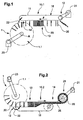
- FIGS 1 to 3 are very schematic representations of portions of various exemplary embodiments of the inventive device for processing piece goods (large numbers of products 20 or treated as units product groups consisting of a small number of individual products). All devices shown have, as an exemplary processing device 1, a processing drum 1.1 to which, according to FIG. 1, a supply unit 10. 1 and, according to FIG. 2, a removal unit 10. 2 are coupled.
- FIG. 3 shows a transfer unit 10.3 coupled on both sides to a respective processing drum 1.1 (combination of removal unit and supply unit).
- the supply, removal or transfer units 10.1, 10.2 or 10.3 each have a self-contained rail track 11, along the one Can be moved in succession plurality of product grippers, not shown.
- the product grippers are independent of each other or they are so together connected that the distances between successive product grippers are variable.
- the rail track connects a receiving area 12, in take the products gripper products 20, over a buffer area 13, in the Product grippers are buffered with products 20, with a delivery area 14, in give products 20 to the product gripper. From the delivery area 14 to the receiving area 12 runs a return path 16 for the return transport of product grippers without products, on which return line 16 the product gripper also buffered can be. If necessary, not all products will be in the delivery area delivered, so that also on the return line isolated product gripper Keep products.
- the drivable areas are in the receiving area 12
- Means arranged to isolate or take over in the case shown
- the Engage product gripper activate and move away. At least a part These functions are driven by a motor drive 21.
- the products 20 are released from the product grippers and positioned in the processing apparatus 1.
- These are the product gripper fed from the buffer area 13 of the positioning, clocked, for positioning deactivated and promoted, with the Eintaktung and deactivation to be exactly synchronized with the operation of the processing device 1.
- a coupling symbolized by the bold arrow 22
- the processing device 1 or at the periphery, for example, a provided mechanical output.
- the Weg Entrystician 10.2 shown in Figure 2 has substantially the same Functional units on how the feed unit 10.1 of Figure 1. These are also denoted by the same reference numerals.
- a means (bold arrow 22) coupled to the processing device 1 arranged for intermittent removal, in the delivery area a means of landfilling of the products 20, for example in flake formation on the feed belt 25 a Aufwickelstation 26.
- the product grab from taken from the buffer area 13, clocked in, deactivated and carried away.
- FIG. 3 shows a transfer unit arranged between two processing drums 1.1 10.3, which is essentially a receiving area 12 with a Temporary withdrawal means and delivery means 14 having means for clocking positioning, which two means for synchronization or are coupled to the drums 1.1 for synchronization and drive (bold Arrows 22).
- the movable feed units, Weg Equipmentsstrahlen and / or transfer units give this not only, as already described above, a great flexibility and simplicity for conversions but they prove themselves by the mechanical separation, which is very close to the processing runs, also as very simple and in particular easily accessible for maintenance, Adjustment work and troubleshooting.
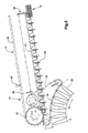
- FIGS. 4 and 5 show in more detail a movable feed unit 10.1 coupled to a processing drum 1.1 (eg saddle stitch drum with saddle-shaped supports).
- FIG. 4 shows the entire delivery unit 10.1, FIG. 5, its delivery area 14 on a larger scale.
- Functional units which have already been described in connection with FIGS. 1 to 3 are designated by the same reference numerals.
- the feed unit 10.1 is in any desired manner, for example manually with supplied stacked products.
- the feeding unit is on wheels or rollers 30 movable and supports height adjustable on the machine frame 31 of the collecting drum 1.1.
- In the delivery area 14 is a to the saddle-shaped pads 32nd the collecting drum 1.1 deliverable toothed belt 33 is provided, the teeth 34th are matched to the outer edges of the saddle-shaped pads 32 and the this is deliverable.
- the timing belt 33 is in the direction of the axis of the drum 1.1 relative to the rail track 11 and the product grippers 40 adjustable shifted.
- this displacement is dimensioned such that the Timing belt 33 in addition to its function as an output and a function as an axial stop for the exact alignment of the saddle-shaped pads 32 positioned Can take over products.
- a suitable transmission 36 provides a means for conveying of product grippers 40 from the buffer area 13 against the positioning and driven to latch the product grippers for positioning.
- This A means for promotion and Eintaktung is for example a corresponding subsidy screw 41 with an increasing towards the point of effective positioning Pitch.
- a Wegnsch Wegfördem the gripper 40 after positioning, for example a driving wheel 42, driven. All other necessary and to be driven for the positioning Means are driven by the toothed belt 33, for example an opening device 50, as shown schematically in Figure 4.
- the opening device 50 is used to open the products to be positioned so that they on the Saddle-shaped pads 32 of the drum 1.1 can be placed.
- the buffer area 13 is advantageously at a location of the rail track 11 provided, at which it falls in the direction against the Zuhege Scheme 14, so that the product grippers 40 are driven by gravity in this area and no mechanical drive must be provided.
- the product grippers are connected by means of slip clutch, are also buffer areas on rising or flat rail areas possible.
- a stacking shaft 51 is provided in the stacked Products are supplied and from these products in a conventional manner and singulated and detected by the product grippers 40.
- a motor Drive 21 drives all for the separation of the partial products from the stacking shaft 51, for their promotion to the point where they are covered by the product grabbers for the hooking of the grapples to this place and for the excavation of the Gripper from this point to the buffer area 13 necessary to be driven Medium on.
- the feed unit 10.1 which is shown in FIGS. 4 and 5, can be used for the Drive in the receiving area 12, so as a drive of the product gripper 40 to the feed and clocking in for the product intake and for the further promotion of the product grippers 40 at least in this area of the rail line 11 a continuously have moving conveyor member to which the product gripper 40, for example are magnetically coupled.
- Such a drive can also extend into the buffer area 13 extend, so that the buffer area also at a in the conveying direction rising piece of rail track 11 may be arranged.
- a system with a self-contained rail track with it independent movable product grippers and one continuously circulating Conveyor to which the product grippers are selectively coupled for example in Publication WO-99/33731 (F475).
- This system is in a feeding unit, as shown in Figures 4 and 5, as a recording drive used.
- FIG. 6 shows a further, exemplary embodiment of the device according to the invention for processing piece goods. Shown is a feed unit 10.1, which is coupled to a processing device 1 in the form of a circulation system 1.2 with V-shaped compartments 60. The products to be supplied 20 are introduced into the V-shaped compartments, for example for the production of multi-part products.
- the feed unit 10.1 is in turn supplied for the supply of stacked Products 20 designed and designated for the separation of products from the Stacking shaft 51 on a occupied with suction cups rotating separating wheel 61
- the product gripper 40 are both in the recording area 12 as well as in the delivery area 14 circumferential drive chains 62 provided in the buffer area 13 and on the return line 16 are the product gripper 40 powered by gravity.
- the Product gripper 40 in the receiving area 12 and discharge area 14 are, for example stationary scenes (not shown) provided.
- the coupling of the delivery drive for the means for positioning the products in the delivery area 14 of the supply unit 10.1 is also in this case by a Timing belt 33 realized, with the outer edges of the V-shaped compartments 60th of the circulating system 1.2 can be brought into engagement.
Landscapes
- Engineering & Computer Science (AREA)
- Mechanical Engineering (AREA)
- Specific Conveyance Elements (AREA)
- Collation Of Sheets And Webs (AREA)
- Vending Machines For Individual Products (AREA)
- Conveyance By Endless Belt Conveyors (AREA)
- Discharge By Other Means (AREA)
- Electrical Discharge Machining, Electrochemical Machining, And Combined Machining (AREA)
Claims (18)
- Installation pour le traitement de produits unitaires, qui comprend au moins un poste de traitement avec au moins une entrée pour des produits (20) à traiter et au moins une sortie pour des produits (20) traités, dans lequel il est prévu à cette entrée un moyen pour le positionnement cadencé de produits (20) isolés en vue du traitement et un moyen pour l'acheminement des produits (20) et à la sortie un moyen pour le retrait cadencé des produits (20) isolés issus du traitement et un moyen pour l'évacuation des produits, caractérisée en ce qu'un dispositif de traitement (1) est prévu pour le traitement et en ce que l'entrée et (ou) la sortie sont conçues comme une unité d'alimentation (10.1) ou une unité d'extraction (10.2) mobile par rapport au dispositif de traitement (1), laquelle unité (10.1, 10.2) comprend une travée de rails (11) fermée, avec une pluralité d'organes de préhension des produits (40) mobiles le long de cette travée de rails et pouvant être déplacés avec des produits (20) d'une zone de prise en charge (12) vers une zone de dépose (14) en passant par une zone tampon (13) et sans produits de la zone de dépose ( 14) vers la zone de prise en charge (12), ainsi qu'un entraínement de prise en charge et un entraínement de dépose indépendant de celui-ci, le moyen de dépose qui entraíne au moins le moyen pour le positionnement cadencé et le moyen d'alimentation dans l'unité d'alimentation (10.1) et le moyen de prise en charge qui entraíne au moins le moyen de retrait cadencé et le moyen d'évacuation dans l'unité d'évacuation (10.2) pouvant être couplés sur la périphérie du dispositif de traitement (1), au moins pour la synchronisation de l'entraínement couplé.
- Installation selon la revendication 1, caractérisée en ce que le couplage de l'entraínement de dépose de l'unité d'alimentation (10.1) et de l'entraínement de prise en charge de l'unité d'évacuation (10.2) est une sortie d'entraínement mécanique pouvant être mise en prise avec des éléments mobiles selon une cadence de traitement et disposés à la périphérie du dispositif de traitement.
- Installation selon la revendication 2, caractérisée en ce que la sortie d'entraínement mécanique est une courroie dentée (33).
- Installation selon l'une ou l'ensemble des revendications 1 à 3, caractérisée en ce que l'unité d'alimentation (10.1) présente dans sa zone de prise en charge (12) un moyen pour la récupération de produits (20) à partir d'un dispositif de transport monté en amont ou un moyen pour l'isolement de produits (20) à partir d'une formation de stockage, lequel moyen est entraíné par l'entraínement de prise en charge.
- Installation selon l'une ou l'ensemble des revendications 1 à 3, caractérisée en ce que l'unité d'évacuation (10.2) présente dans sa zone de dépose (14) un moyen pour le transfert de produits vers un dispositif de transport monté en aval ou un moyen pour le dépôt ordonné de produits, lequel moyen est entraíné par l'entraínement de dépose.
- Installation selon l'une ou l'ensemble des revendications 1 à 3, caractérisée en ce que l'unité d'alimentation avec l'entraínement de dépose pouvant être couplé au premier dispositif de traitement est conçue comme une unité de transfert (10.3) en cela qu'elle présente dans sa zone de prise en charge un moyen pour le prélèvement cadencé de produits à partir d'un deuxième poste de traitement et un moyen pour l'évacuation des produits, l'entraínement de prise en charge entraínant lesdits moyens pouvant être couplé à la périphérie d'un deuxième dispositif de traitement.
- Installation selon l'une ou l'ensemble des revendications 1 à 6, caractérisée en ce que l'unité d'alimentation (10.1), l'unité d'évacuation (10.2) et (ou) l'unité de transfert (10.3) sont mobiles sur des galets ou des roues (30) et peuvent s'appuyer de façon mobile verticalement sur un bâti de machine (31) du dispositif de traitement (1).
- Installation selon l'une ou l'ensemble des revendications 1 à 7, caractérisée en ce que le dispositif de traitement (1) au nombre d'un au moins présente un moyen pour la fabrication de produits à partir d'une pluralité de parties de produit et une pluralité de supports en forme de sellette (32), de compartiments en forme de V (60) ou de supports d'empilement, et en ce que l'entraínement de dépose et l'entraínement de prise en charge peuvent être couplés aux supports en forme de sellette (32), compartiments en forme de V (60) ou supports d'empilement.
- Installation selon la revendication 8, caractérisée en ce que le dispositif de traitement (1) est un tambour (1.1) tournant, dans lequel les supports en forme de sellette (32) ou les compartiments en forme de V (60) sont entraínés en rotation autour d'un axe de tambour (A), ou un système de circulation (1.2) avec une trajectoire fermée pour les supports en forme de sellette (32), les compartiments en forme de V (60) ou les supports d'empilement.
- Installation selon la revendication 8 ou 9, caractérisée en ce que la courroie dentée (33) peut être mise en prise avec des bords extérieurs de supports en forme de sellette (32) ou de compartiments en forme de V.
- Installation selon la revendication 10, caractérisée en ce qu'il est prévu au niveau des supports en forme de sellette (32) ou des compartiments en forme de V (60) des moyens d'orientation avec lesquels les produits sont poussés, après un positionnement, contre la courroie dentée (33) servant de butée.
- Installation selon l'une ou l'ensemble des revendications 1 à 11, caractérisée en ce que l'unité d'alimentation (10.1) ou l'unité de transfert (10.3) présente dans la zone de dépose (14), comme moyen de positionnement et d'avancement, une vis de transport (41) agissant sur les organes de préhension des produits (40) et une roue d'entraínement (42).
- Installation selon l'une ou l'ensemble des revendications 1 à 12, caractérisée en ce que l'unité d'alimentation (10.1) ou l'unité de transfert (10.3) présente dans la zone de dépose (14), comme moyens d'avancement et de positionnement, une courroie d'entraínement (62) agissant sur les organes de préhension des produits (40).
- Installation selon l'une ou l'ensemble des revendications 1 à 13, caractérisée en ce que l'unité d'alimentation (10.1) ou l'unité de transfert (10.3) présente dans la zone de dépose (14) un dispositif d'ouverture (50) entraíné par l'entraínement de dépose.
- Installation selon l'une ou l'ensemble des revendications 1 à 14, caractérisée en ce que l'unité d'alimentation (10.1) présente dans la zone de prise en charge (12) une courroie d'entraínement (62) agissant sur les organes de préhension des produits (40) et qui fait partie de l'entraínement de prise en charge.
- Installation selon l'une ou l'ensemble des revendications 1 à 15, caractérisée en ce que l'unité d'alimentation (10.1) présente dans la zone de prise en charge (12) un caisson d'empilement (51) et un moyen (61) pour isoler les produits (20) empilés sans fixation dans le caisson d'empilement (51).
- Installation selon l'une ou l'ensemble des revendications 1 à 16, caractérisée en ce que la travée de rails (11) est inclinée en pente descendante dans la zone de tampon (13) de l'unité d'alimentation (10.1) en direction de la zone de dépose (14), ou dans celle de l'unité d'évacuation (10.2) en direction de la zone de prise en charge (12).
- Installation selon l'une ou l'ensemble des revendications 1 à 16, caractérisée en ce que l'unité d'alimentation (10.1) présente dans la zone de prise en charge (12) un organe de transport circulant sur lequel les organes de préhension des produits (40) peuvent être couplés de façon sélective, et en ce que cet organe de transport s'étend au moins jusqu'à la zone de transport (13).
Applications Claiming Priority (3)
| Application Number | Priority Date | Filing Date | Title |
|---|---|---|---|
| CH7452000 | 2000-04-14 | ||
| CH745002000 | 2000-04-14 | ||
| CH7452000 | 2000-04-14 |
Publications (3)
| Publication Number | Publication Date |
|---|---|
| EP1146000A2 EP1146000A2 (fr) | 2001-10-17 |
| EP1146000A3 EP1146000A3 (fr) | 2002-08-28 |
| EP1146000B1 true EP1146000B1 (fr) | 2003-12-10 |
Family
ID=4533439
Family Applications (1)
| Application Number | Title | Priority Date | Filing Date |
|---|---|---|---|
| EP01810294A Expired - Lifetime EP1146000B1 (fr) | 2000-04-14 | 2001-03-22 | Dispositif pour traiter des articles |
Country Status (9)
| Country | Link |
|---|---|
| US (1) | US6814352B2 (fr) |
| EP (1) | EP1146000B1 (fr) |
| JP (1) | JP2002003087A (fr) |
| AT (1) | ATE256067T1 (fr) |
| AU (1) | AU778235B2 (fr) |
| CA (1) | CA2342663C (fr) |
| DE (1) | DE50101104D1 (fr) |
| DK (1) | DK1146000T3 (fr) |
| RU (1) | RU2266250C2 (fr) |
Families Citing this family (6)
| Publication number | Priority date | Publication date | Assignee | Title |
|---|---|---|---|---|
| US20050098942A1 (en) * | 2003-11-07 | 2005-05-12 | Heidelberger Druckmaschinen Ag | Pin conveyor for printed sheet material and transfer unit |
| CH700240A1 (de) * | 2009-01-08 | 2010-07-15 | Ferag Ag | Vorrichtung und verfahren zum transfer von flexiblen flachen gegenständen. |
| CH700413A1 (de) * | 2009-02-06 | 2010-08-13 | Ferag Ag | Vorrichtung und Verfahren zum Transfer von flexiblen flachen Gegenständen. |
| EP2233313A1 (fr) * | 2009-03-13 | 2010-09-29 | Müller Martini Holding AG | Procédé et dispositifs de fabrication de résultats d'impression constitués de plusieurs produits d'impression formés et reliés à l'aide de colle |
| EP2246283B1 (fr) * | 2009-05-01 | 2014-09-24 | Müller Martini Holding AG | Dispositif et procédé de traitement de produits d'impression |
| CH712497A1 (de) * | 2016-05-30 | 2017-11-30 | Ferag Ag | Zuführvorrichtung zum Zuführen von Produkten an eine Weiterverarbeitungsvorrichtung. |
Family Cites Families (15)
| Publication number | Priority date | Publication date | Assignee | Title |
|---|---|---|---|---|
| US2232720A (en) * | 1937-02-19 | 1941-02-25 | Smithe Machine Co Inc F L | Delivery mechanism |
| DE1153383B (de) * | 1959-12-23 | 1963-08-29 | Ferag Fehr & Reist A G | Einrichtung zum Ablegen der bogenfoermigen Produkte einer Rotationsdruckmaschine |
| US3770144A (en) * | 1971-12-06 | 1973-11-06 | Owens Illinois Inc | Corrugated board bundle stacker |
| CH575303A5 (fr) * | 1975-02-26 | 1976-05-14 | Ferag Ag | |
| CH618398A5 (fr) * | 1977-06-06 | 1980-07-31 | Ferag Ag | |
| CH680851A5 (fr) * | 1988-01-08 | 1992-11-30 | Ferag Ag | |
| US5088711A (en) * | 1990-08-27 | 1992-02-18 | Newsome John R | Machine for transporting and loading signatures |
| EP0550828B1 (fr) | 1992-01-10 | 1995-08-09 | Ferag AG | Procédé et dispositif de traitement de produits imprimés |
| EP0633212B1 (fr) * | 1993-07-07 | 1997-03-26 | Ferag AG | Dispositif de transport circulant sans fin pour charge isolée avec organes de transport individuels |
| CH688091A5 (de) * | 1994-08-11 | 1997-05-15 | Ferag Ag | Flexibles Foerdersystem. |
| DK0719720T3 (da) | 1994-12-30 | 1998-04-27 | Ferag Ag | Oplagringsanordning til en rulleenhed og anordning til forarbejdning af trykkeriprodukter |
| CH690300A5 (de) | 1995-09-20 | 2000-07-14 | Ferag Ag | Verfahren zur Zuführung von Druckprodukten in Form von Schuppenströmen zu Verarbeitungsstationen und Anordnung zur Durchführung des Verfahrens. |
| US6237744B1 (en) * | 1996-07-19 | 2001-05-29 | Ferag Ag | Apparatus for supplying printed products to a discharge location |
| US5913656A (en) | 1997-11-14 | 1999-06-22 | Collins; Michael A. | Method and apparatus for merging shingled signature streams |
| AU743762B2 (en) | 1997-12-23 | 2002-02-07 | Ferag Ag | Conveyor system |
-
2001
- 2001-03-22 DK DK01810294T patent/DK1146000T3/da active
- 2001-03-22 AT AT01810294T patent/ATE256067T1/de not_active IP Right Cessation
- 2001-03-22 DE DE50101104T patent/DE50101104D1/de not_active Expired - Lifetime
- 2001-03-22 EP EP01810294A patent/EP1146000B1/fr not_active Expired - Lifetime
- 2001-03-27 AU AU31334/01A patent/AU778235B2/en not_active Ceased
- 2001-03-30 CA CA002342663A patent/CA2342663C/fr not_active Expired - Fee Related
- 2001-04-10 RU RU2001109443/03A patent/RU2266250C2/ru not_active IP Right Cessation
- 2001-04-11 JP JP2001112879A patent/JP2002003087A/ja not_active Withdrawn
- 2001-04-13 US US09/834,793 patent/US6814352B2/en not_active Expired - Lifetime
Also Published As
| Publication number | Publication date |
|---|---|
| DE50101104D1 (de) | 2004-01-22 |
| JP2002003087A (ja) | 2002-01-09 |
| CA2342663A1 (fr) | 2001-10-14 |
| CA2342663C (fr) | 2007-08-28 |
| AU778235B2 (en) | 2004-11-25 |
| RU2266250C2 (ru) | 2005-12-20 |
| EP1146000A2 (fr) | 2001-10-17 |
| EP1146000A3 (fr) | 2002-08-28 |
| US6814352B2 (en) | 2004-11-09 |
| DK1146000T3 (da) | 2004-04-13 |
| US20010050460A1 (en) | 2001-12-13 |
| AU3133401A (en) | 2001-10-18 |
| ATE256067T1 (de) | 2003-12-15 |
Similar Documents
| Publication | Publication Date | Title |
|---|---|---|
| DE3645393B4 (de) | Sammelhefter | |
| DE3316740A1 (de) | Vorrichtung zum zusammentragen von zeitungen | |
| EP2263956B9 (fr) | Dispositif de transport pour le transport de produits d'impression et installation dotée d'un tel dispositif de transport | |
| DE19523164A1 (de) | Flexibles Fördersystem | |
| EP0680916B1 (fr) | Procédé de traitement de produits imprimés | |
| EP1146000B1 (fr) | Dispositif pour traiter des articles | |
| EP1523443B1 (fr) | Procede et dispositif pour constituer des piles horizontales (barres) de produits d'imprimerie et pour les cercler | |
| EP0514783B1 (fr) | Dispositif pour transporter des piles de feuilles en papier | |
| EP0344102A2 (fr) | Dispositif d'assemblage de produits imprimés | |
| EP0765247B1 (fr) | Procede et dispositif pour traiter des produits imprimes | |
| EP1528023B1 (fr) | Méthode et dispositif pour changer un flux d'articles plats | |
| EP1309504B1 (fr) | Procede et dispositif de production de piles en croix | |
| DE3330681A1 (de) | Verfahren zum schnellen zufuehren und transportieren von blattfoermigen papiererzeugnissen und vorrichtung zur durchfuehrung des verfahrens | |
| DE19510901B4 (de) | Vorrichtung zum Verarbeiten von Druckereiprodukten | |
| EP2301874B1 (fr) | Procédé de collecte de produits d'impression et dispositif de collecte pour produits d'impression | |
| EP1155992B1 (fr) | Méthode et dispositif pour diviser un courant de transport d'articles | |
| EP2383214B1 (fr) | Dispositif d'assemblage | |
| EP3208098B1 (fr) | Machine à appliquer les couvertures et procédé de fourniture de couvertures de livre | |
| DE4415047A1 (de) | Verfahren und Vorrichtung zum Fördern von Blattlagen aus einer Sammelstation | |
| EP3064453B1 (fr) | Procédé et dispositif de fabrication de paquets a partir de produits d'imprimerie | |
| EP2571794B1 (fr) | Installation de traitement ultérieur d'impression et procédé pour faire fonctionner une installation de traitement ultérieur d'impression | |
| CH690300A5 (de) | Verfahren zur Zuführung von Druckprodukten in Form von Schuppenströmen zu Verarbeitungsstationen und Anordnung zur Durchführung des Verfahrens. | |
| EP2205514B1 (fr) | Dispositif et procédé de production de produits imprimés multi-pièces | |
| EP0216023A1 (fr) | Dispositif pour ordonner un courant d'articles se chevauchant | |
| EP1492422B1 (fr) | Dispositif de division d'une suite continue d'articles et procede correspondant |
Legal Events
| Date | Code | Title | Description |
|---|---|---|---|
| PUAI | Public reference made under article 153(3) epc to a published international application that has entered the european phase |
Free format text: ORIGINAL CODE: 0009012 |
|
| AK | Designated contracting states |
Kind code of ref document: A2 Designated state(s): AT BE CH CY DE DK ES FI FR GB GR IE IT LI LU MC NL PT SE TR |
|
| AX | Request for extension of the european patent |
Free format text: AL;LT;LV;MK;RO;SI |
|
| PUAL | Search report despatched |
Free format text: ORIGINAL CODE: 0009013 |
|
| AK | Designated contracting states |
Kind code of ref document: A3 Designated state(s): AT BE CH CY DE DK ES FI FR GB GR IE IT LI LU MC NL PT SE TR |
|
| AX | Request for extension of the european patent |
Free format text: AL;LT;LV;MK;RO;SI |
|
| 17P | Request for examination filed |
Effective date: 20030129 |
|
| GRAH | Despatch of communication of intention to grant a patent |
Free format text: ORIGINAL CODE: EPIDOS IGRA |
|
| AKX | Designation fees paid |
Designated state(s): AT BE CH CY DE DK ES FI FR GB GR IE IT LI LU MC NL PT SE TR |
|
| GRAS | Grant fee paid |
Free format text: ORIGINAL CODE: EPIDOSNIGR3 |
|
| GRAA | (expected) grant |
Free format text: ORIGINAL CODE: 0009210 |
|
| AK | Designated contracting states |
Kind code of ref document: B1 Designated state(s): AT BE CH CY DE DK ES FI FR GB GR IE IT LI LU MC NL PT SE TR |
|
| PG25 | Lapsed in a contracting state [announced via postgrant information from national office to epo] |
Ref country code: NL Free format text: LAPSE BECAUSE OF FAILURE TO SUBMIT A TRANSLATION OF THE DESCRIPTION OR TO PAY THE FEE WITHIN THE PRESCRIBED TIME-LIMIT Effective date: 20031210 Ref country code: CY Free format text: LAPSE BECAUSE OF FAILURE TO SUBMIT A TRANSLATION OF THE DESCRIPTION OR TO PAY THE FEE WITHIN THE PRESCRIBED TIME-LIMIT Effective date: 20031210 Ref country code: FI Free format text: LAPSE BECAUSE OF FAILURE TO SUBMIT A TRANSLATION OF THE DESCRIPTION OR TO PAY THE FEE WITHIN THE PRESCRIBED TIME-LIMIT Effective date: 20031210 Ref country code: TR Free format text: LAPSE BECAUSE OF FAILURE TO SUBMIT A TRANSLATION OF THE DESCRIPTION OR TO PAY THE FEE WITHIN THE PRESCRIBED TIME-LIMIT Effective date: 20031210 Ref country code: IE Free format text: LAPSE BECAUSE OF FAILURE TO SUBMIT A TRANSLATION OF THE DESCRIPTION OR TO PAY THE FEE WITHIN THE PRESCRIBED TIME-LIMIT Effective date: 20031210 |
|
| REG | Reference to a national code |
Ref country code: GB Ref legal event code: FG4D Free format text: NOT ENGLISH |
|
| REG | Reference to a national code |
Ref country code: CH Ref legal event code: EP |
|
| REG | Reference to a national code |
Ref country code: IE Ref legal event code: FG4D Free format text: GERMAN |
|
| REF | Corresponds to: |
Ref document number: 50101104 Country of ref document: DE Date of ref document: 20040122 Kind code of ref document: P |
|
| REG | Reference to a national code |
Ref country code: CH Ref legal event code: NV Representative=s name: FREI PATENTANWALTSBUERO |
|
| GBT | Gb: translation of ep patent filed (gb section 77(6)(a)/1977) |
Effective date: 20040204 |
|
| PG25 | Lapsed in a contracting state [announced via postgrant information from national office to epo] |
Ref country code: GR Free format text: LAPSE BECAUSE OF FAILURE TO SUBMIT A TRANSLATION OF THE DESCRIPTION OR TO PAY THE FEE WITHIN THE PRESCRIBED TIME-LIMIT Effective date: 20040310 |
|
| REG | Reference to a national code |
Ref country code: SE Ref legal event code: TRGR |
|
| PG25 | Lapsed in a contracting state [announced via postgrant information from national office to epo] |
Ref country code: ES Free format text: LAPSE BECAUSE OF FAILURE TO SUBMIT A TRANSLATION OF THE DESCRIPTION OR TO PAY THE FEE WITHIN THE PRESCRIBED TIME-LIMIT Effective date: 20040321 |
|
| PG25 | Lapsed in a contracting state [announced via postgrant information from national office to epo] |
Ref country code: LU Free format text: LAPSE BECAUSE OF NON-PAYMENT OF DUE FEES Effective date: 20040322 Ref country code: AT Free format text: LAPSE BECAUSE OF NON-PAYMENT OF DUE FEES Effective date: 20040322 |
|
| PG25 | Lapsed in a contracting state [announced via postgrant information from national office to epo] |
Ref country code: BE Free format text: LAPSE BECAUSE OF NON-PAYMENT OF DUE FEES Effective date: 20040331 Ref country code: MC Free format text: LAPSE BECAUSE OF NON-PAYMENT OF DUE FEES Effective date: 20040331 |
|
| REG | Reference to a national code |
Ref country code: DK Ref legal event code: T3 |
|
| NLV1 | Nl: lapsed or annulled due to failure to fulfill the requirements of art. 29p and 29m of the patents act | ||
| REG | Reference to a national code |
Ref country code: IE Ref legal event code: FD4D |
|
| ET | Fr: translation filed | ||
| BERE | Be: lapsed |
Owner name: FERAG AG Effective date: 20040331 |
|
| PLBE | No opposition filed within time limit |
Free format text: ORIGINAL CODE: 0009261 |
|
| STAA | Information on the status of an ep patent application or granted ep patent |
Free format text: STATUS: NO OPPOSITION FILED WITHIN TIME LIMIT |
|
| 26N | No opposition filed |
Effective date: 20040913 |
|
| REG | Reference to a national code |
Ref country code: CH Ref legal event code: PFA Owner name: FERAG AG Free format text: FERAG AG#ZUERICHSTRASSE 74#8340 HINWIL (CH) -TRANSFER TO- FERAG AG#PATENTABTEILUNG Z. H. MARKUS FELIX ZUERICHSTRASSE 74#8340 HINWIL (CH) |
|
| PG25 | Lapsed in a contracting state [announced via postgrant information from national office to epo] |
Ref country code: PT Free format text: LAPSE BECAUSE OF NON-PAYMENT OF DUE FEES Effective date: 20040510 |
|
| PGFP | Annual fee paid to national office [announced via postgrant information from national office to epo] |
Ref country code: SE Payment date: 20140319 Year of fee payment: 14 Ref country code: DK Payment date: 20140319 Year of fee payment: 14 |
|
| PGFP | Annual fee paid to national office [announced via postgrant information from national office to epo] |
Ref country code: FR Payment date: 20140319 Year of fee payment: 14 Ref country code: IT Payment date: 20140326 Year of fee payment: 14 |
|
| PGFP | Annual fee paid to national office [announced via postgrant information from national office to epo] |
Ref country code: GB Payment date: 20140319 Year of fee payment: 14 |
|
| REG | Reference to a national code |
Ref country code: DE Ref legal event code: R082 Ref document number: 50101104 Country of ref document: DE Representative=s name: PATENTANWAELTE UND RECHTSANWALT DR. WEISS, ARA, DE Ref country code: DE Ref legal event code: R082 Ref document number: 50101104 Country of ref document: DE Representative=s name: PATENTANWAELTE UND RECHTSANWALT WEISS, ARAT & , DE |
|
| REG | Reference to a national code |
Ref country code: DK Ref legal event code: EBP Effective date: 20150331 |
|
| GBPC | Gb: european patent ceased through non-payment of renewal fee |
Effective date: 20150322 |
|
| PG25 | Lapsed in a contracting state [announced via postgrant information from national office to epo] |
Ref country code: SE Free format text: LAPSE BECAUSE OF NON-PAYMENT OF DUE FEES Effective date: 20150323 |
|
| REG | Reference to a national code |
Ref country code: SE Ref legal event code: EUG |
|
| PG25 | Lapsed in a contracting state [announced via postgrant information from national office to epo] |
Ref country code: IT Free format text: LAPSE BECAUSE OF NON-PAYMENT OF DUE FEES Effective date: 20150322 |
|
| REG | Reference to a national code |
Ref country code: FR Ref legal event code: ST Effective date: 20151130 |
|
| PG25 | Lapsed in a contracting state [announced via postgrant information from national office to epo] |
Ref country code: GB Free format text: LAPSE BECAUSE OF NON-PAYMENT OF DUE FEES Effective date: 20150322 |
|
| PG25 | Lapsed in a contracting state [announced via postgrant information from national office to epo] |
Ref country code: FR Free format text: LAPSE BECAUSE OF NON-PAYMENT OF DUE FEES Effective date: 20150331 |
|
| PG25 | Lapsed in a contracting state [announced via postgrant information from national office to epo] |
Ref country code: DK Free format text: LAPSE BECAUSE OF NON-PAYMENT OF DUE FEES Effective date: 20150331 |
|
| PGFP | Annual fee paid to national office [announced via postgrant information from national office to epo] |
Ref country code: DE Payment date: 20180322 Year of fee payment: 18 |
|
| PGFP | Annual fee paid to national office [announced via postgrant information from national office to epo] |
Ref country code: CH Payment date: 20180606 Year of fee payment: 18 |
|
| REG | Reference to a national code |
Ref country code: DE Ref legal event code: R119 Ref document number: 50101104 Country of ref document: DE |
|
| REG | Reference to a national code |
Ref country code: CH Ref legal event code: PL |
|
| PG25 | Lapsed in a contracting state [announced via postgrant information from national office to epo] |
Ref country code: LI Free format text: LAPSE BECAUSE OF NON-PAYMENT OF DUE FEES Effective date: 20190331 Ref country code: DE Free format text: LAPSE BECAUSE OF NON-PAYMENT OF DUE FEES Effective date: 20191001 Ref country code: CH Free format text: LAPSE BECAUSE OF NON-PAYMENT OF DUE FEES Effective date: 20190331 |