EP1147314B1 - Kraftstoffhochdruckpumpe - Google Patents
Kraftstoffhochdruckpumpe Download PDFInfo
- Publication number
- EP1147314B1 EP1147314B1 EP00988995A EP00988995A EP1147314B1 EP 1147314 B1 EP1147314 B1 EP 1147314B1 EP 00988995 A EP00988995 A EP 00988995A EP 00988995 A EP00988995 A EP 00988995A EP 1147314 B1 EP1147314 B1 EP 1147314B1
- Authority
- EP
- European Patent Office
- Prior art keywords
- piston
- pump
- plate
- shutter
- cylinder
- Prior art date
- Legal status (The legal status is an assumption and is not a legal conclusion. Google has not performed a legal analysis and makes no representation as to the accuracy of the status listed.)
- Expired - Lifetime
Links
- 239000000446 fuel Substances 0.000 title claims description 16
- 230000006835 compression Effects 0.000 claims description 16
- 238000007906 compression Methods 0.000 claims description 16
- 238000002485 combustion reaction Methods 0.000 claims description 4
- 230000000295 complement effect Effects 0.000 claims description 2
- 238000006243 chemical reaction Methods 0.000 description 1
- 238000010586 diagram Methods 0.000 description 1
- 239000012530 fluid Substances 0.000 description 1
- 238000005086 pumping Methods 0.000 description 1
Images

Classifications
-
- F—MECHANICAL ENGINEERING; LIGHTING; HEATING; WEAPONS; BLASTING
- F02—COMBUSTION ENGINES; HOT-GAS OR COMBUSTION-PRODUCT ENGINE PLANTS
- F02M—SUPPLYING COMBUSTION ENGINES IN GENERAL WITH COMBUSTIBLE MIXTURES OR CONSTITUENTS THEREOF
- F02M37/00—Apparatus or systems for feeding liquid fuel from storage containers to carburettors or fuel-injection apparatus; Arrangements for purifying liquid fuel specially adapted for, or arranged on, internal-combustion engines
- F02M37/04—Feeding by means of driven pumps
- F02M37/06—Feeding by means of driven pumps mechanically driven
-
- F—MECHANICAL ENGINEERING; LIGHTING; HEATING; WEAPONS; BLASTING
- F02—COMBUSTION ENGINES; HOT-GAS OR COMBUSTION-PRODUCT ENGINE PLANTS
- F02M—SUPPLYING COMBUSTION ENGINES IN GENERAL WITH COMBUSTIBLE MIXTURES OR CONSTITUENTS THEREOF
- F02M59/00—Pumps specially adapted for fuel-injection and not provided for in groups F02M39/00 -F02M57/00, e.g. rotary cylinder-block type of pumps
- F02M59/02—Pumps specially adapted for fuel-injection and not provided for in groups F02M39/00 -F02M57/00, e.g. rotary cylinder-block type of pumps of reciprocating-piston or reciprocating-cylinder type
- F02M59/04—Pumps specially adapted for fuel-injection and not provided for in groups F02M39/00 -F02M57/00, e.g. rotary cylinder-block type of pumps of reciprocating-piston or reciprocating-cylinder type characterised by special arrangement of cylinders with respect to piston-driving shaft, e.g. arranged parallel to that shaft or swash-plate type pumps
- F02M59/06—Pumps specially adapted for fuel-injection and not provided for in groups F02M39/00 -F02M57/00, e.g. rotary cylinder-block type of pumps of reciprocating-piston or reciprocating-cylinder type characterised by special arrangement of cylinders with respect to piston-driving shaft, e.g. arranged parallel to that shaft or swash-plate type pumps with cylinders arranged radially to driving shaft, e.g. in V or star arrangement
-
- F—MECHANICAL ENGINEERING; LIGHTING; HEATING; WEAPONS; BLASTING
- F02—COMBUSTION ENGINES; HOT-GAS OR COMBUSTION-PRODUCT ENGINE PLANTS
- F02M—SUPPLYING COMBUSTION ENGINES IN GENERAL WITH COMBUSTIBLE MIXTURES OR CONSTITUENTS THEREOF
- F02M63/00—Other fuel-injection apparatus having pertinent characteristics not provided for in groups F02M39/00 - F02M57/00 or F02M67/00; Details, component parts, or accessories of fuel-injection apparatus, not provided for in, or of interest apart from, the apparatus of groups F02M39/00 - F02M61/00 or F02M67/00; Combination of fuel pump with other devices, e.g. lubricating oil pump
- F02M63/02—Fuel-injection apparatus having several injectors fed by a common pumping element, or having several pumping elements feeding a common injector; Fuel-injection apparatus having provisions for cutting-out pumps, pumping elements, or injectors; Fuel-injection apparatus having provisions for variably interconnecting pumping elements and injectors alternatively
- F02M63/0225—Fuel-injection apparatus having a common rail feeding several injectors ; Means for varying pressure in common rails; Pumps feeding common rails
-
- F—MECHANICAL ENGINEERING; LIGHTING; HEATING; WEAPONS; BLASTING
- F04—POSITIVE - DISPLACEMENT MACHINES FOR LIQUIDS; PUMPS FOR LIQUIDS OR ELASTIC FLUIDS
- F04B—POSITIVE-DISPLACEMENT MACHINES FOR LIQUIDS; PUMPS
- F04B1/00—Multi-cylinder machines or pumps characterised by number or arrangement of cylinders
- F04B1/04—Multi-cylinder machines or pumps characterised by number or arrangement of cylinders having cylinders in star- or fan-arrangement
- F04B1/0404—Details or component parts
- F04B1/0421—Cylinders
-
- F—MECHANICAL ENGINEERING; LIGHTING; HEATING; WEAPONS; BLASTING
- F04—POSITIVE - DISPLACEMENT MACHINES FOR LIQUIDS; PUMPS FOR LIQUIDS OR ELASTIC FLUIDS
- F04B—POSITIVE-DISPLACEMENT MACHINES FOR LIQUIDS; PUMPS
- F04B53/00—Component parts, details or accessories not provided for in, or of interest apart from, groups F04B1/00 - F04B23/00 or F04B39/00 - F04B47/00
- F04B53/10—Valves; Arrangement of valves
- F04B53/102—Disc valves
- F04B53/1022—Disc valves having means for guiding the closure member axially
Definitions
- the present invention relates to a high-pressure hydraulic pump, in particular an internal combustion engine radial-piston fuel pump.
- such a pump operates at high pressure, even as high as 160 MPa (1,600 bars), and comprises a group of radial cylinders in which slide respective pistons activated by a common cam.
- Each piston has a return spring so as to move elastically during the fuel intake stroke, and is associated with an intake valve comprising a shutter which is normally kept closed by another return spring for opening the valve when overcome by the intake fuel pressure.
- each shutter has a plate cooperating with a corresponding seat in the cylinder, and is opened when the intake fuel pressure reaches roughly 500 kPa (5 bars); and the reaction of the three pistons on the drive shaft is normally balanced by the 120° spacing of the pistons.
- a high-pressure hydraulic pump comprising at least one cylinder in which slides a piston, and actuating means for moving said piston positively in a compression direction; said piston being moved elastically in an intake direction opposite to said compression direction; and an intake valve comprising a shutter being fitted to said cylinder; said elastic means being provided between said piston and said shutter to push said shutter into a closed position by exerting elastic force varying with the position of said piston in said cylinder, so as to advance opening and closing of said intake valve; the pump being characterised in that said piston directly acts on said elastic means for varying said force; wherein said shutter comprises a plate cooperating with a seat of said intake valve; said plate being movable parallel to said piston and said elastic means comprising a compression spring located between said plate and said piston; said piston having a cylindrical appendix coaxial with said plate and for securing one end of said spring.
- the elastic means comprise a helical compression spring located between the plate and the piston.
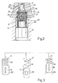
- Number 5 in Figure 1 indicates as a whole a high-pressure pump for supplying fuel to an internal combustion engine, e.g. a diesel engine.
- Pump 5 is a radial-piston type, and comprises three cylinders 6 - only one shown in Figure 1 - arranged radially inside a hollow body 7, with the respective axes 120° apart. More specifically, cylinders 6 are formed in one piece with hollow body 7, which is closed by a flange 8.
- Pump 5 has a drive shaft 9 integral with an eccentric 11 housed in a central chamber 12 of hollow body 7.
- Eccentric 11 carries an annular cam for controlling pump 5 and which is defined by a ring 13 rotating on eccentric 11.
- the outer surface of ring 13 has three flat portions 14 associated with cylinders 6 and each perpendicular to the axis of the corresponding cylinder 6.
- a respective piston 16 slides in each cylinder 6; the outer radial surface of piston 16 defines a compression chamber 15 in cylinder 6; and piston 16 projects from cylinder 6 towards shaft 9, and carries a pad 17 which slides in known manner on the corresponding portion 14 of ring 13.
- ring 13 moves pistons 16 positively and sequentially in the compression direction, i.e. outwards.
- pad 17 is pushed elastically, together with piston 16, in the intake direction towards the corresponding flat portion 14 of ring 13.
- Each piston 16 is associated with an intake valve 19 comprising a shutter 21 cooperating with a seat 22 ( Figure 2) formed in a valve body 23 and coaxial with the corresponding cylinder 6.
- Valve body 23 is integral with cylinder 6 and hence with hollow body 7 ( Figure 1), and is fixed to hollow body 7 by a fluidtight ring nut fastening member 24.
- Each piston 16 is also associated with a delivery valve not shown in the drawings.
- valve body 23 ( Figure 2) is bell-shaped and comprises a substantially cylindrical cavity 27 facing piston 16 and housing part of spring 26.
- Seat 22 is located inside cavity 27 and is truncated-cone-shaped, flaring towards compression chamber 15.
- Shutter 21 comprises a plate 28 integral with a stem 29, which is guided by an axial hole 31 in valve body 23; axial hole 31 has an enlargement 30 communicating with a supply conduit 32 of valve body 23; and conduit 32 communicates with supply channels 33 ( Figure 1) carried by hollow body 7 and/or flange 8.
- plate 28 On the side facing stem 29, plate 28 has a truncated-cone-shaped edge 35 complementary in shape to that of seat 22. On the side facing away from stem 29, plate 28 carries a cylindrical projection 34 for securing one end of spring 26.
- the outer radial surface of piston 16 has a cylindrical appendix 36 smaller in diameter than piston 16; and the other end of compression spring 26 is secured to cylindrical appendix 36 of piston 16.
- intake valve 19 When the difference in pressure between supply conduit 32 and compression chamber 15 is greater than the force exerted by the decompressed spring 26, intake valve 19 is opened. Intake valve 19 is thus opened promptly and in advance with respect to known valves, even in the presence of low fuel pressure or flow in supply conduit 32. Fuel is then drawn along supply channels 33 and conduit 32 in valve body 23. The force exerted by spring 26 on plate 28 of shutter 21 is reduced to minimum at the bottom dead center position of piston 16, but the fuel pressure in chamber 15 remains the same as in supply conduit 32.
- Eccentric 11 then begins moving piston 16 positively outwards to begin compressing the fuel in chamber 15. Piston 16 also begins compressing spring 26, which increases the elastic force exerted on plate 28 of shutter 21, which is then closed by the fuel pressure in chamber 15 together with the force exerted by spring 26. Valve 19 is therefore closed promptly and in advance with respect to known valves, thus providing for greater compression efficiency. Compression continues until piston 16 once more reaches the top dead center position.
- Figure 3 shows the relative positions of the three pistons 16 and relative shutters 21 of pump 5 in the course of a typical stage in the operation of ecentric 11.
- the three cylinders 6 are indicated A, B and C. More specifically, in cylinder 6A, piston 16 is at the start of the intake stroke, close to the top dead center position; and, though shutter 21 is still closed, spring 26 begins extending and reducing the force exerted on shutter 21.
- piston 16 moves towards the bottom dead center position; spring 26 is only slightly compressed; and shutter 21 is opened even in the presence of low fuel pressure in supply channels 33.
- piston 16 has begun the compression stroke and has also begun to compress spring 26, so that shutter 21 is closed immediately.
- shutter 21 is opened and closed more rapidly, even with low fuel pressure in the supply conduit; and operation of the pump is balanced and continuous.
- cylinders 6 may be separate from, and inserted inside holes in, hollow body 7; and each valve body 23 may be fitted to hollow body 7, together with the corresponding cylinder, by means of a fastening plate.
- Seat 22 of intake valve 19 may be flat as opposed to truncated-cone-shaped; and the pump may even be a single-piston or multiple-in-line-piston type, and be used for pumping fluids other than engine fuel.
Landscapes
- Engineering & Computer Science (AREA)
- Mechanical Engineering (AREA)
- General Engineering & Computer Science (AREA)
- Chemical & Material Sciences (AREA)
- Combustion & Propulsion (AREA)
- Details Of Reciprocating Pumps (AREA)
- Fuel-Injection Apparatus (AREA)
- Reciprocating Pumps (AREA)
Claims (8)
- Hochdruck-Hydraulikpumpe mit mindestens einem Zylinder (6), in dem ein Kolben (16) gleitet, und Betätigungsmitteln (9, 11) zum positiven Bewegen des Kolbens (16) in einer Verdichtungsrichtung; wobei der Kolben (16) in einer der Verdichtungsrichtung entgegengesetzten Einlassrichtung elastisch bewegt wird; und einem Einlassventil (19), das einen an dem Zylinder (6) angebrachten Schließkörper (21) umfasst; wobei elastische Mittel (26) zwischen dem Kolben (16) und dem Schließkörper (21) vorgesehen sind, um den Schließkörper (21) durch Ausüben einer elastischen Kraft, die mit der Position des Kolbens (16) in dem Zylinder (6) variiert, in eine geschlossene Stellung zu drücken, um ein Öffnen und Schließen des Einlassventils (19) vorzuverstellen; wobei die Pumpe dadurch gekennzeichnet ist, dass der Kolben (16) auf die elastischen Mittel direkt einwirkt, um die Kraft zu variieren; wobei der Schließkörper (21) eine Platte (28) umfasst, die mit einem Sitz (22) des Einlassventils (19) zusammenwirkt; wobei die Platte (28) parallel zum Kolben (16) beweglich ist und die elastischen Mittel eine Druckfeder (26) umfassen, die zwischen der Platte (28) und dem Kolben (16) angeordnet ist; wobei der Kolben (16) einen zylindrischen Ansatz (36) aufweist, der mit der Platte (28) koaxial ist und ein Ende der Feder (26) befestigt.
- Pumpe nach Anspruch 1, dadurch gekennzeichnet, dass der Schließkörper (21) des Weiteren einen integral mit der Platte (28) ausgebildeten Schaft (29) aufweist, der sich radial nach außen erstreckt; wobei der Schaft innerhalb eines axialen Lochs (31) des Ventilkörpers (23) in dem Einlassventil (19) geführt wird.
- Pumpe nach Anspruch 2, dadurch gekennzeichnet, dass der Sitz (22) kegelstumpfförmig ist und sich zum Kolben (16) hin aufweitet; wobei die Platte (28) auf der zum Schaft weisenden Seite einen kegelstumpfförmigen Rand (35) komplementär zur Form des Sitzes (22) aufweist.
- Pumpe nach Anspruch 3, dadurch gekennzeichnet, dass die Platte auf der dem Schaft gegenüberliegenden Seite einen zylindrischen Vorsprung (34) zur Befestigung eines anderen Endes der Feder (26) umfasst.
- Pumpe nach einem der Ansprüche 2 bis 4, bei der der Sitz (22) koaxial zum Zylinder (6) ist und von einem an dem Zylinder (6) angebrachten Ventilkörper (23) getragen wird; wobei der Ventilkörper (23) eine Versorgungsleitung (32) aufweist; dadurch gekennzeichnet, dass der Ventilkörper (23) zur Aufnahme mindestens eines Teils der Feder (26) glockenförmig ist.
- Pumpe nach einem der Ansprüche 2 bis 5, dadurch gekennzeichnet, dass das axiale Loch (31) eine mit der Versorgungsleitung (32) in Verbindung stehende Erweiterung (30) aufweist.
- Pumpe nach Anspruch 6, der Radialkolbenart für Verbrennungsmotorkraftstoff, mit einem durch einen Flansch (8) geschlossenen Hohlkörper (7); wobei der Hohlkörper (7) eine Gruppe von radialen Zylindern (6) trägt, die einer entsprechenden Gruppe von Kolben (16) und einer entsprechenden Gruppe von Einlassventilen (19) zugeordnet sind; und wobei die Kolben (16) durch einen gemeinsamen Exzenter (11) aktiviert werden; dadurch gekennzeichnet, dass jeder der Ventilkörper (23) mittels eines fluiddichten Befestigungsglieds (24) in dem Hohlkörper (7) befestigt ist; wobei das Befestigungsglied (24) von außen in dem Hohlkörper (7) angebracht werden kann.
- Pumpe nach Anspruch 7, dadurch gekennzeichnet, dass die Versorgungsleitung (32) jedes Ventilkörpers (23) mit einem im Hohlkörper (7) und/oder im Flansch (8) ausgebildeten Versorgungskanal (33) in Verbindung steht.
Applications Claiming Priority (3)
| Application Number | Priority Date | Filing Date | Title |
|---|---|---|---|
| IT1999TO001055A IT1310755B1 (it) | 1999-11-30 | 1999-11-30 | Pompa idraulica ad alta pressione, in particolare pompa a pistoniradiali per il carburante di un motore a combustione interna. |
| ITTO991055 | 1999-11-30 | ||
| PCT/IT2000/000488 WO2001040657A1 (en) | 1999-11-30 | 2000-11-29 | High-pressure hydraulic fuel pump |
Publications (2)
| Publication Number | Publication Date |
|---|---|
| EP1147314A1 EP1147314A1 (de) | 2001-10-24 |
| EP1147314B1 true EP1147314B1 (de) | 2006-07-19 |
Family
ID=11418263
Family Applications (1)
| Application Number | Title | Priority Date | Filing Date |
|---|---|---|---|
| EP00988995A Expired - Lifetime EP1147314B1 (de) | 1999-11-30 | 2000-11-29 | Kraftstoffhochdruckpumpe |
Country Status (8)
| Country | Link |
|---|---|
| US (1) | US6558142B2 (de) |
| EP (1) | EP1147314B1 (de) |
| JP (1) | JP4902923B2 (de) |
| KR (1) | KR100706171B1 (de) |
| AU (1) | AU2546101A (de) |
| DE (1) | DE60029422T2 (de) |
| IT (1) | IT1310755B1 (de) |
| WO (1) | WO2001040657A1 (de) |
Families Citing this family (12)
| Publication number | Priority date | Publication date | Assignee | Title |
|---|---|---|---|---|
| DE10218022A1 (de) * | 2002-04-23 | 2003-11-06 | Bosch Gmbh Robert | Kraftstoffeinspritzeinrichtung für eine Brennkraftmaschine |
| DE10239728A1 (de) * | 2002-08-29 | 2004-03-11 | Robert Bosch Gmbh | Pumpe, insbesondere für eine Kraftstoffeinspritzeinrichtung für eine Brennkraftmaschine |
| DE10346211A1 (de) * | 2003-05-22 | 2004-12-09 | Robert Bosch Gmbh | Rückschlagventil, insbesondere für eine Hochdruckpumpe einer Kraftstoffeinspritzeinrichtung für eine Brennkraftmaschine |
| DE502004007338D1 (de) * | 2003-05-22 | 2008-07-17 | Bosch Gmbh Robert | Rückschlagventil, insbesondere für eine Hochdruckpumpe einer Kraftstoffeinspritzeinrichtung für eine Brennkraftmaschine |
| DE102004028999A1 (de) * | 2004-06-16 | 2006-01-05 | Robert Bosch Gmbh | Hochdruckpumpe für eine Kraftstoffeinspritzeinrichtung einer Brennkraftmaschine |
| DE102006017036A1 (de) * | 2006-04-11 | 2007-10-18 | Siemens Ag | Radialkolbenpumpe zur Kraftstoff-Hochdruckversorgung bei einer Brennkraftmaschine |
| DE102008048450B4 (de) * | 2008-09-23 | 2014-10-30 | Continental Automotive Gmbh | Saugventil für einen Zylinder der Kraftstoff-Hochdruckpumpe eines Common-Rail-Einspritzsystems |
| IT1402403B1 (it) * | 2010-10-21 | 2013-09-04 | Bosch Gmbh Robert | Gruppo di pompaggio per alimentare combustibile, preferibilmente gasolio, ad un motore a combustione interna. |
| ITMI20121819A1 (it) * | 2012-10-25 | 2014-04-26 | Bosch Gmbh Robert | Unita' di pompaggio per alimentare combustibile, preferibilmente gasolio, ad un motore a combustione interna |
| EP2746566A1 (de) * | 2012-12-18 | 2014-06-25 | Delphi International Operations Luxembourg S.à r.l. | Pumpeinheit |
| ITMI20130811A1 (it) * | 2013-05-17 | 2014-11-18 | Bosch Gmbh Robert | Unita' di pompaggio per alimentare combustibile, preferibilmente gasolio, ad un motore a combustione interna |
| US10012228B2 (en) * | 2014-04-17 | 2018-07-03 | Danfoss Power Solutions Gmbh & Co. Ohg | Variable fluid flow hydraulic pump |
Family Cites Families (19)
| Publication number | Priority date | Publication date | Assignee | Title |
|---|---|---|---|---|
| JPS5787171A (en) * | 1980-11-20 | 1982-05-31 | Toshiba Corp | Optical thyristor device |
| JPS60194164A (ja) * | 1984-03-12 | 1985-10-02 | 中小企業事業団 | 繊維材料の連続泡処理装置 |
| DE3437973A1 (de) * | 1984-10-17 | 1986-04-17 | Robert Bosch Gmbh, 7000 Stuttgart | Kraftstoffeinspritzpumpe fuer brennkraftmaschinen |
| JPS61124761A (ja) * | 1984-11-21 | 1986-06-12 | Daifuku Co Ltd | 遊星歯車機構 |
| JPS6379477A (ja) * | 1986-09-24 | 1988-04-09 | Nec Corp | 映像信号直流安定化方式 |
| JPH0452569A (ja) * | 1990-06-20 | 1992-02-20 | Sumitomo Wiring Syst Ltd | 導通検査用導通板 |
| JPH0465969A (ja) * | 1990-07-02 | 1992-03-02 | Oki Electric Ind Co Ltd | 画像処理装置 |
| DE4419927A1 (de) * | 1994-06-08 | 1995-12-14 | Bosch Gmbh Robert | Kolbenpumpe |
| DE19612412B4 (de) * | 1996-03-28 | 2006-07-06 | Siemens Ag | Regelung für ein Druckfluid-Versorgungssystem, insbesondere für den Hochdruck in einem Kraftstoff-Einspritzsystem |
| IT1289796B1 (it) * | 1996-12-23 | 1998-10-16 | Elasis Sistema Ricerca Fiat | Perfezionamenti ad un dispositivo a pompa per l'alimentazione del carburante da un serbatoio ad un motore a combustione interna. |
| IT239879Y1 (it) * | 1996-12-23 | 2001-03-13 | Elasis Sistema Ricerca Fiat | Perfezionamenti ad una pompa a pistoni, in particolare ad una pompa apistoni radiali per il carburante di un motore a combustione interna. |
| DE19729790C2 (de) * | 1997-07-11 | 2002-08-29 | Bosch Gmbh Robert | Radialkolbenpumpe zur Kraftstoffhochdruckversorgung |
| DE19729791A1 (de) * | 1997-07-11 | 1999-01-14 | Bosch Gmbh Robert | Radialkolbenpumpe zur Kraftstoffhochdruckversorgung |
| JP2857139B1 (ja) * | 1998-01-30 | 1999-02-10 | 三菱電機株式会社 | 高圧燃料供給ポンプ |
| DE19804275A1 (de) * | 1998-02-04 | 1999-08-12 | Bosch Gmbh Robert | Radialkolbenpumpe zur Kraftstoffhochdruckversorgung |
| DE19818385A1 (de) * | 1998-04-24 | 1999-10-28 | Bosch Gmbh Robert | Zuschaltventil in einem Kraftstoffeinspritzsystem für Brennkraftmaschinen |
| DE19848035A1 (de) * | 1998-10-17 | 2000-04-20 | Bosch Gmbh Robert | Radialkolbenpumpe für Kraftstoffhochdruckerzeugung |
| DE19848040A1 (de) * | 1998-10-17 | 2000-04-20 | Bosch Gmbh Robert | Kolbenpumpe zur Kraftstoffhochdruckversorgung |
| DE19858483A1 (de) * | 1998-12-18 | 2000-08-31 | Mannesmann Rexroth Ag | Hydraulische Verdrängermaschine, insbesondere Verdrängerpumpe |
-
1999
- 1999-11-30 IT IT1999TO001055A patent/IT1310755B1/it active
-
2000
- 2000-11-29 WO PCT/IT2000/000488 patent/WO2001040657A1/en not_active Ceased
- 2000-11-29 AU AU25461/01A patent/AU2546101A/en not_active Abandoned
- 2000-11-29 DE DE60029422T patent/DE60029422T2/de not_active Expired - Lifetime
- 2000-11-29 JP JP2001542690A patent/JP4902923B2/ja not_active Expired - Fee Related
- 2000-11-29 KR KR1020017009607A patent/KR100706171B1/ko not_active Expired - Fee Related
- 2000-11-29 EP EP00988995A patent/EP1147314B1/de not_active Expired - Lifetime
-
2001
- 2001-07-19 US US09/908,715 patent/US6558142B2/en not_active Expired - Fee Related
Also Published As
| Publication number | Publication date |
|---|---|
| DE60029422T2 (de) | 2006-11-30 |
| ITTO991055A1 (it) | 2001-05-30 |
| ITTO991055A0 (it) | 1999-11-30 |
| DE60029422D1 (de) | 2006-08-31 |
| IT1310755B1 (it) | 2002-02-22 |
| US6558142B2 (en) | 2003-05-06 |
| EP1147314A1 (de) | 2001-10-24 |
| KR100706171B1 (ko) | 2007-04-11 |
| KR20010093298A (ko) | 2001-10-27 |
| JP2003524099A (ja) | 2003-08-12 |
| US20020034452A1 (en) | 2002-03-21 |
| JP4902923B2 (ja) | 2012-03-21 |
| WO2001040657A1 (en) | 2001-06-07 |
| AU2546101A (en) | 2001-06-12 |
Similar Documents
| Publication | Publication Date | Title |
|---|---|---|
| US5571243A (en) | Pump device for supplying fuel from a tank to an internal combustion engine | |
| EP1147314B1 (de) | Kraftstoffhochdruckpumpe | |
| US10041457B2 (en) | Pump unit | |
| KR101785276B1 (ko) | 밸브 제어 방법 및 장치 | |
| EP2476895A2 (de) | Hochdruckbrennstoffförderpumpe | |
| EP0726390B1 (de) | Brennstoffsystem | |
| EP1442213B1 (de) | Einlassventil für eine hochdruckpumpe, insbesondere für kraftstoff einer brennkraftmaschine | |
| JP2004537005A (ja) | 高圧供給ポンプ | |
| US20080069712A1 (en) | High-Pressure Pump for a Fuel Injection System of an Internal Combustion Engine | |
| EP3635240B1 (de) | Hp-pumpe für dieseleinspritzsysteme | |
| US10907630B2 (en) | Relief valve device and high-pressure pump using same | |
| JP2003097387A (ja) | 高圧燃料供給装置 | |
| JP2003049743A (ja) | 内燃機関の燃料系用の燃料ポンプ | |
| CN101627186B (zh) | 用于液压控制往复式内燃机的换气阀的装置 | |
| KR19990007475A (ko) | 가변 송출형 가압 연료 펌프 | |
| US7048516B2 (en) | High pressure fuel pump with multiple radial plungers | |
| EP3126643B1 (de) | Gaswechselventilanordnung | |
| WO2019206606A1 (en) | Pumping unit for feeding fuel, preferably diesel fuel, to an internal combustion engine | |
| JP2002054531A (ja) | ピストン式高圧ポンプ | |
| WO2003067035A1 (en) | Hydraulic control system for a gas exchange valve of an internal combustion engine | |
| US20040050349A1 (en) | Variable force engine valve actuator | |
| EP3176422B1 (de) | Kraftstoffpumpe | |
| JP2003343392A (ja) | 高圧燃料供給装置 | |
| CN117242261A (zh) | 用于活塞泵的活塞、用于制造活塞的方法以及活塞泵 | |
| JPH11236863A (ja) | 内面カム式燃料噴射ポンプ |
Legal Events
| Date | Code | Title | Description |
|---|---|---|---|
| PUAI | Public reference made under article 153(3) epc to a published international application that has entered the european phase |
Free format text: ORIGINAL CODE: 0009012 |
|
| AK | Designated contracting states |
Kind code of ref document: A1 Designated state(s): AT BE CH CY DE DK ES FI FR GB GR IE IT LI LU MC NL PT SE TR |
|
| AX | Request for extension of the european patent |
Free format text: AL;LT;LV;MK;RO;SI |
|
| 17P | Request for examination filed |
Effective date: 20011205 |
|
| RBV | Designated contracting states (corrected) |
Designated state(s): DE FR GB IT |
|
| 17Q | First examination report despatched |
Effective date: 20050620 |
|
| GRAP | Despatch of communication of intention to grant a patent |
Free format text: ORIGINAL CODE: EPIDOSNIGR1 |
|
| GRAS | Grant fee paid |
Free format text: ORIGINAL CODE: EPIDOSNIGR3 |
|
| GRAA | (expected) grant |
Free format text: ORIGINAL CODE: 0009210 |
|
| AK | Designated contracting states |
Kind code of ref document: B1 Designated state(s): DE FR GB IT |
|
| PG25 | Lapsed in a contracting state [announced via postgrant information from national office to epo] |
Ref country code: IT Free format text: LAPSE BECAUSE OF FAILURE TO SUBMIT A TRANSLATION OF THE DESCRIPTION OR TO PAY THE FEE WITHIN THE PRESCRIBED TIME-LIMIT;WARNING: LAPSES OF ITALIAN PATENTS WITH EFFECTIVE DATE BEFORE 2007 MAY HAVE OCCURRED AT ANY TIME BEFORE 2007. THE CORRECT EFFECTIVE DATE MAY BE DIFFERENT FROM THE ONE RECORDED. Effective date: 20060719 |
|
| REG | Reference to a national code |
Ref country code: GB Ref legal event code: FG4D |
|
| REF | Corresponds to: |
Ref document number: 60029422 Country of ref document: DE Date of ref document: 20060831 Kind code of ref document: P |
|
| ET | Fr: translation filed | ||
| PLBE | No opposition filed within time limit |
Free format text: ORIGINAL CODE: 0009261 |
|
| STAA | Information on the status of an ep patent application or granted ep patent |
Free format text: STATUS: NO OPPOSITION FILED WITHIN TIME LIMIT |
|
| 26N | No opposition filed |
Effective date: 20070420 |
|
| PGFP | Annual fee paid to national office [announced via postgrant information from national office to epo] |
Ref country code: DE Payment date: 20130124 Year of fee payment: 13 |
|
| PGFP | Annual fee paid to national office [announced via postgrant information from national office to epo] |
Ref country code: FR Payment date: 20131119 Year of fee payment: 14 Ref country code: GB Payment date: 20131122 Year of fee payment: 14 |
|
| PGFP | Annual fee paid to national office [announced via postgrant information from national office to epo] |
Ref country code: IT Payment date: 20131125 Year of fee payment: 14 |
|
| REG | Reference to a national code |
Ref country code: DE Ref legal event code: R119 Ref document number: 60029422 Country of ref document: DE Effective date: 20140603 |
|
| PG25 | Lapsed in a contracting state [announced via postgrant information from national office to epo] |
Ref country code: DE Free format text: LAPSE BECAUSE OF NON-PAYMENT OF DUE FEES Effective date: 20140603 |
|
| GBPC | Gb: european patent ceased through non-payment of renewal fee |
Effective date: 20141129 |
|
| REG | Reference to a national code |
Ref country code: FR Ref legal event code: ST Effective date: 20150731 |
|
| PG25 | Lapsed in a contracting state [announced via postgrant information from national office to epo] |
Ref country code: GB Free format text: LAPSE BECAUSE OF NON-PAYMENT OF DUE FEES Effective date: 20141129 |
|
| PG25 | Lapsed in a contracting state [announced via postgrant information from national office to epo] |
Ref country code: FR Free format text: LAPSE BECAUSE OF NON-PAYMENT OF DUE FEES Effective date: 20141201 |
|
| PG25 | Lapsed in a contracting state [announced via postgrant information from national office to epo] |
Ref country code: IT Free format text: LAPSE BECAUSE OF NON-PAYMENT OF DUE FEES Effective date: 20141129 |