EP1147962A1 - Verfahren zur Regelung eines hydraulischen Kraftfahrzeugbremssystems - Google Patents
Verfahren zur Regelung eines hydraulischen Kraftfahrzeugbremssystems Download PDFInfo
- Publication number
- EP1147962A1 EP1147962A1 EP01109057A EP01109057A EP1147962A1 EP 1147962 A1 EP1147962 A1 EP 1147962A1 EP 01109057 A EP01109057 A EP 01109057A EP 01109057 A EP01109057 A EP 01109057A EP 1147962 A1 EP1147962 A1 EP 1147962A1
- Authority
- EP
- European Patent Office
- Prior art keywords
- hydraulic pressure
- brake
- master cylinder
- passage
- valve
- Prior art date
- Legal status (The legal status is an assumption and is not a legal conclusion. Google has not performed a legal analysis and makes no representation as to the accuracy of the status listed.)
- Withdrawn
Links
- 238000000034 method Methods 0.000 title claims abstract description 15
- 239000012530 fluid Substances 0.000 claims description 32
- 238000001514 detection method Methods 0.000 claims description 6
- 239000007788 liquid Substances 0.000 abstract description 8
- XLYOFNOQVPJJNP-UHFFFAOYSA-N water Substances O XLYOFNOQVPJJNP-UHFFFAOYSA-N 0.000 abstract description 7
- 230000000881 depressing effect Effects 0.000 description 4
- 230000000052 comparative effect Effects 0.000 description 3
- 230000010349 pulsation Effects 0.000 description 2
- 230000000994 depressogenic effect Effects 0.000 description 1
- 238000010586 diagram Methods 0.000 description 1
Images

Classifications
-
- B—PERFORMING OPERATIONS; TRANSPORTING
- B60—VEHICLES IN GENERAL
- B60T—VEHICLE BRAKE CONTROL SYSTEMS OR PARTS THEREOF; BRAKE CONTROL SYSTEMS OR PARTS THEREOF, IN GENERAL; ARRANGEMENT OF BRAKING ELEMENTS ON VEHICLES IN GENERAL; PORTABLE DEVICES FOR PREVENTING UNWANTED MOVEMENT OF VEHICLES; VEHICLE MODIFICATIONS TO FACILITATE COOLING OF BRAKES
- B60T8/00—Arrangements for adjusting wheel-braking force to meet varying vehicular or ground-surface conditions, e.g. limiting or varying distribution of braking force
- B60T8/32—Arrangements for adjusting wheel-braking force to meet varying vehicular or ground-surface conditions, e.g. limiting or varying distribution of braking force responsive to a speed condition, e.g. acceleration or deceleration
- B60T8/34—Arrangements for adjusting wheel-braking force to meet varying vehicular or ground-surface conditions, e.g. limiting or varying distribution of braking force responsive to a speed condition, e.g. acceleration or deceleration having a fluid pressure regulator responsive to a speed condition
- B60T8/40—Arrangements for adjusting wheel-braking force to meet varying vehicular or ground-surface conditions, e.g. limiting or varying distribution of braking force responsive to a speed condition, e.g. acceleration or deceleration having a fluid pressure regulator responsive to a speed condition comprising an additional fluid circuit including fluid pressurising means for modifying the pressure of the braking fluid, e.g. including wheel driven pumps for detecting a speed condition, or pumps which are controlled by means independent of the braking system
- B60T8/4072—Systems in which a driver input signal is used as a control signal for the additional fluid circuit which is normally used for braking
- B60T8/4081—Systems with stroke simulating devices for driver input
-
- B—PERFORMING OPERATIONS; TRANSPORTING
- B60—VEHICLES IN GENERAL
- B60T—VEHICLE BRAKE CONTROL SYSTEMS OR PARTS THEREOF; BRAKE CONTROL SYSTEMS OR PARTS THEREOF, IN GENERAL; ARRANGEMENT OF BRAKING ELEMENTS ON VEHICLES IN GENERAL; PORTABLE DEVICES FOR PREVENTING UNWANTED MOVEMENT OF VEHICLES; VEHICLE MODIFICATIONS TO FACILITATE COOLING OF BRAKES
- B60T13/00—Transmitting braking action from initiating means to ultimate brake actuator with power assistance or drive; Brake systems incorporating such transmitting means, e.g. air-pressure brake systems
- B60T13/10—Transmitting braking action from initiating means to ultimate brake actuator with power assistance or drive; Brake systems incorporating such transmitting means, e.g. air-pressure brake systems with fluid assistance, drive, or release
- B60T13/66—Electrical control in fluid-pressure brake systems
- B60T13/662—Electrical control in fluid-pressure brake systems characterised by specified functions of the control system components
-
- B—PERFORMING OPERATIONS; TRANSPORTING
- B60—VEHICLES IN GENERAL
- B60T—VEHICLE BRAKE CONTROL SYSTEMS OR PARTS THEREOF; BRAKE CONTROL SYSTEMS OR PARTS THEREOF, IN GENERAL; ARRANGEMENT OF BRAKING ELEMENTS ON VEHICLES IN GENERAL; PORTABLE DEVICES FOR PREVENTING UNWANTED MOVEMENT OF VEHICLES; VEHICLE MODIFICATIONS TO FACILITATE COOLING OF BRAKES
- B60T7/00—Brake-action initiating means
- B60T7/02—Brake-action initiating means for personal initiation
- B60T7/04—Brake-action initiating means for personal initiation foot actuated
- B60T7/042—Brake-action initiating means for personal initiation foot actuated by electrical means, e.g. using travel or force sensors
-
- B—PERFORMING OPERATIONS; TRANSPORTING
- B60—VEHICLES IN GENERAL
- B60T—VEHICLE BRAKE CONTROL SYSTEMS OR PARTS THEREOF; BRAKE CONTROL SYSTEMS OR PARTS THEREOF, IN GENERAL; ARRANGEMENT OF BRAKING ELEMENTS ON VEHICLES IN GENERAL; PORTABLE DEVICES FOR PREVENTING UNWANTED MOVEMENT OF VEHICLES; VEHICLE MODIFICATIONS TO FACILITATE COOLING OF BRAKES
- B60T8/00—Arrangements for adjusting wheel-braking force to meet varying vehicular or ground-surface conditions, e.g. limiting or varying distribution of braking force
- B60T8/32—Arrangements for adjusting wheel-braking force to meet varying vehicular or ground-surface conditions, e.g. limiting or varying distribution of braking force responsive to a speed condition, e.g. acceleration or deceleration
- B60T8/34—Arrangements for adjusting wheel-braking force to meet varying vehicular or ground-surface conditions, e.g. limiting or varying distribution of braking force responsive to a speed condition, e.g. acceleration or deceleration having a fluid pressure regulator responsive to a speed condition
- B60T8/40—Arrangements for adjusting wheel-braking force to meet varying vehicular or ground-surface conditions, e.g. limiting or varying distribution of braking force responsive to a speed condition, e.g. acceleration or deceleration having a fluid pressure regulator responsive to a speed condition comprising an additional fluid circuit including fluid pressurising means for modifying the pressure of the braking fluid, e.g. including wheel driven pumps for detecting a speed condition, or pumps which are controlled by means independent of the braking system
- B60T8/404—Control of the pump unit
-
- B—PERFORMING OPERATIONS; TRANSPORTING
- B60—VEHICLES IN GENERAL
- B60T—VEHICLE BRAKE CONTROL SYSTEMS OR PARTS THEREOF; BRAKE CONTROL SYSTEMS OR PARTS THEREOF, IN GENERAL; ARRANGEMENT OF BRAKING ELEMENTS ON VEHICLES IN GENERAL; PORTABLE DEVICES FOR PREVENTING UNWANTED MOVEMENT OF VEHICLES; VEHICLE MODIFICATIONS TO FACILITATE COOLING OF BRAKES
- B60T8/00—Arrangements for adjusting wheel-braking force to meet varying vehicular or ground-surface conditions, e.g. limiting or varying distribution of braking force
- B60T8/32—Arrangements for adjusting wheel-braking force to meet varying vehicular or ground-surface conditions, e.g. limiting or varying distribution of braking force responsive to a speed condition, e.g. acceleration or deceleration
- B60T8/34—Arrangements for adjusting wheel-braking force to meet varying vehicular or ground-surface conditions, e.g. limiting or varying distribution of braking force responsive to a speed condition, e.g. acceleration or deceleration having a fluid pressure regulator responsive to a speed condition
- B60T8/40—Arrangements for adjusting wheel-braking force to meet varying vehicular or ground-surface conditions, e.g. limiting or varying distribution of braking force responsive to a speed condition, e.g. acceleration or deceleration having a fluid pressure regulator responsive to a speed condition comprising an additional fluid circuit including fluid pressurising means for modifying the pressure of the braking fluid, e.g. including wheel driven pumps for detecting a speed condition, or pumps which are controlled by means independent of the braking system
- B60T8/4072—Systems in which a driver input signal is used as a control signal for the additional fluid circuit which is normally used for braking
Definitions
- This invention relates to a method of controlling a vehicle hydraulic brake system provided with a hydraulic pressure source for producing brake hydraulic pressure.
- a vehicle hydraulic brake system in which a hydraulic pressure source for producing brake hydraulic pressure is provided and a driving device for the hydraulic pressure source is actuated based on a detection signal from a brake operating force detecting means for detecting the operating force applied to a brake operating member.
- a brake fluid replenish passage communicating a master cylinder and wheel cylinders with each other, and an on-off valve and a check valve for preventing reverse flow from the wheel cylinder side toward the master cylinder are mounted in the replenish passage to replenish brake fluid from the master cylinder toward the wheel cylinders if the amount of brake fluid from the hydraulic pressure source is insufficient.
- a brake fluid replenish passage In a brake system provided with such a brake fluid replenish passage, the brake hydraulic pressure in the wheel cylinders and the hydraulic pressure in the master cylinder are detected, and the on-off valve in the replenish passage is opened when the pressure difference between the master cylinder hydraulic pressure and the brake hydraulic pressure exceeds a predetermined value, to replenish brake fluid from the master cylinder side to the wheel cylinders.
- This replenish passage is opened in the initial period of brake operation, in which due to the fact that the consumed fluid amount in the wheel cylinders is large, a hydraulic pressure difference between the master cylinder hydraulic pressure and the brake hydraulic pressure tends to occur.
- brake hydraulic pressure is produced only by the hydraulic pressure source by closing the replenish passage, using the pressure difference between the master cylinder hydraulic pressure and the brake hydraulic pressure as an input signal for control, the driving force by the driving device for the hydraulic pressure source is PID-controlled.
- the master cylinder for producing hydraulic pressure according to the operating force applied to the brake operating member is in communication with wheel cylinders through the on-off valve by way of the so-called master cylinder passage. If the hydraulic pressure source is not operating normally, the hydraulic pressure in the master cylinder is transmitted as brake hydraulic pressure by opening the on-off valve to provide a failsafe function.
- An object of this invention is to provide a method of controlling a hydraulic pressure source-driven type vehicle hydraulic brake system in which water hammering or worsening of the pedal feeling will not happen when brake liquid is replenished through the replenish passage.
- a method of controlling a vehicle hydraulic brake system comprising a brake operating member, a master cylinder for producing hydraulic pressure corresponding to a brake operating force applied to the brake operating member, a wheel cylinder, a hydraulic pressure source for producing brake hydraulic pressure in the wheel cylinder, a driving device for the hydraulic pressure source, a fluid passage for bringing the hydraulic pressure source into communication with the wheel cylinder, a fluid replenish passage for bringing the master cylinder and the wheel cylinder into communication with each other, an on-off valve and a check valve provided in the fluid replenish passage, the check valve preventing a reverse flow from the wheel cylinder toward the master cylinder, a brake operating force detecting means for detecting the brake operating force, a brake hydraulic pressure detecting means for detecting the brake hydraulic pressure in the wheel cylinder, and a master cylinder hydraulic pressure detecting means for detecting the hydraulic pressure in the master cylinder, the driving device for the hydraulic pressure source and the on-off valve in the fluid replenish passage being actuated based on signals from the brake operating force
- the on-off valve in the replenish passage is closed to return to normal control mode in which the driving force of the driving device for the hydraulic pressure source is controlled so as to correspond to the difference between the master cylinder hydraulic pressure and the brake hydraulic pressure.
- This control method of a vehicle hydraulic brake system can be applied to a brake system in which a master cylinder passage for bringing the master cylinder and the wheel cylinder into communication with each other through an on-off valve is provided, and the on-off valve in the master cylinder passage is selectively opened and closed to transmit the hydraulic pressure produced in the master cylinder to the wheel cylinder.
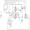
- Fig. 1 shows a vehicle hydraulic brake system to which is applied the control method of the present invention.
- This brake system has a pump 1 as a hydraulic pressure source, and a motor 2 as its driving device.
- the pump 1 is mounted in a fluid passage 5 bringing a reservoir tank 3 and a wheel cylinder 4 into communication with each other.
- a brake pedal 6 as a brake operating member is coupled to a master cylinder 8 through a booster 7.
- the master cylinder 8 and the wheel cylinder 4 are brought into communication with each other by a master cylinder passage 10 through a solenoid valve 9, which is an on-off valve. They also communicate with each other through a brake fluid replenish passage 13 in which a solenoid valve 11 and a check valve 12 are mounted in series and which is provided parallel to the master cylinder passage 10.
- the check valve 12 serves to prevent the brake fluid from flowing from the wheel cylinder 4 toward the master cylinder 8. Between the wheel cylinder 4 and the reservoir tank 3, there is also provided a brake fluid relief passage 15 in which a solenoid valve 14 is mounted.
- pressure sensors 16a, 16b for detecting the hydraulic pressure in the master cylinder 8 and the brake hydraulic pressure in the wheel cylinder 4, respectively, are mounted.
- the pressure sensor 16a is also used for the detection of pedal depressing force, that is, a brake operating force.
- the detection signals from the pressure sensors 16a, 16b are put into a controller 17, which based on these detection signals, controls the operation of the motor 2 and solenoid valves 9, 11 and 14.
- the controller 17 shuts off the master cylinder passage 10 by closing the solenoid valve 9, and actuates the motor 2 and the solenoid valve 11 in the below-described control method, thereby producing brake fluid pressure in the wheel cylinder 4. But if the amount of brake fluid supplied to the wheel cylinder 4 is insufficient for some reason and the controller 17 judges that the brake hydraulic pressure detected by the pressure sensor 16b is insufficient, it will open the solenoid valve 9 in the master cylinder passage 10 to transmit the hydraulic pressure in the master cylinder 8 to the wheel cylinder 4 to produce a sufficient brake hydraulic pressure.
- the controller 17 detects the depressing of the brake pedal 6 and closes the solenoid valve 14 in the relief passage 15. When it detects the release of the brake pedal 6, it releases the braking force by opening the solenoid valve 14, and returns brake fluid supplied to the wheel cylinder 4 to the reservoir tank 3.
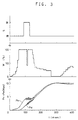
- the graph of Fig. 2 shows, with the time t from the start of depressing of the brake pedal 6 as abscissa, changes in the master cylinder hydraulic pressure PM detected by the pressure sensor 16a, and the brake hydraulic pressure PW in the wheel cylinder 4 detected by the pressure sensor 16b, which are input signals of control, and the motor driving force W, which is an output signal of control, and an on-off signal S to the solenoid valve 11 in the replenish passage 13, arranged in parallel.
- the controller 17 When the brake pedal 6 begins to be depressed, and the master cylinder hydraulic pressure PM, which also serves to detect the brake operating force, reaches a predetermined value (0.5 MPa), the controller 17 will open the solenoid valve 11 in the replenish passage 13, activates the motor 2, and sets its driving force at 100% to replenish brake fluid from the master cylinder 8 to the wheel cylinder 4.
- the brake hydraulic pressure PW will quickly increase so as to follow the rise of the master cylinder hydraulic pressure PM.
- the controller 17 will close the solenoid valve 11 and almost simultaneously change the command of motor driving force W to a control in which the hydraulic pressure difference ⁇ P is used as an input signal to control the motor driving force W by PID control.
- the on-off valve in the brake liquid replenish passage is opened and the driving device for the hydraulic pressure source is actuated at a full driving force in the initial stage of brake operation in which the difference between the master cylinder pressure and the brake hydraulic pressure is small and the brake operating force reaches a predetermined value.
- the on-off valve in the replenish passage is closed to return to the normal control in which the driving force of the driving device for the hydraulic pressure source is controlled so as to correspond to the hydraulic pressure difference between the master cylinder pressure and the brake hydraulic pressure.
Landscapes
- Engineering & Computer Science (AREA)
- Physics & Mathematics (AREA)
- Fluid Mechanics (AREA)
- Transportation (AREA)
- Mechanical Engineering (AREA)
- Regulating Braking Force (AREA)
Applications Claiming Priority (2)
| Application Number | Priority Date | Filing Date | Title |
|---|---|---|---|
| JP2000118185 | 2000-04-19 | ||
| JP2000118185A JP2001301596A (ja) | 2000-04-19 | 2000-04-19 | 車両用液圧ブレーキシステムの制御方法 |
Publications (1)
| Publication Number | Publication Date |
|---|---|
| EP1147962A1 true EP1147962A1 (de) | 2001-10-24 |
Family
ID=18629375
Family Applications (1)
| Application Number | Title | Priority Date | Filing Date |
|---|---|---|---|
| EP01109057A Withdrawn EP1147962A1 (de) | 2000-04-19 | 2001-04-11 | Verfahren zur Regelung eines hydraulischen Kraftfahrzeugbremssystems |
Country Status (3)
| Country | Link |
|---|---|
| US (1) | US6371576B2 (de) |
| EP (1) | EP1147962A1 (de) |
| JP (1) | JP2001301596A (de) |
Families Citing this family (3)
| Publication number | Priority date | Publication date | Assignee | Title |
|---|---|---|---|---|
| JP4507354B2 (ja) * | 2000-05-24 | 2010-07-21 | 株式会社アドヴィックス | 車両用液圧ブレーキシステムの制御方法 |
| US6533369B2 (en) * | 2000-10-19 | 2003-03-18 | Delphi Technologies, Inc. | Brake system and method having secondary hydraulic braking in a de-energized operational mode |
| JP5103917B2 (ja) * | 2007-02-01 | 2012-12-19 | 株式会社アドヴィックス | 車両の運動制御装置 |
Citations (5)
| Publication number | Priority date | Publication date | Assignee | Title |
|---|---|---|---|---|
| EP0734929A1 (de) * | 1995-03-31 | 1996-10-02 | Lucas Industries Public Limited Company | Elektrohydraulische Bremsanlage |
| DE19638920A1 (de) * | 1996-09-23 | 1998-03-26 | Teves Gmbh Alfred | Hydraulische Bremsanlage mit Bremskraftverstärkung |
| DE19753786A1 (de) * | 1997-12-04 | 1999-06-10 | Itt Mfg Enterprises Inc | Bremsanlage für Kraftfahrzeuge |
| DE19828553C1 (de) * | 1998-06-26 | 2000-02-03 | Bosch Gmbh Robert | Verfahren und Vorrichtungen zur Durchführung eines Verfahrens zur Bildung oder Anpassung eines Ansteuersignals zur Ansteuerung eines ein Druckmedium fördernden Mittels eines Fahrzeugbremssystems |
| DE19962649A1 (de) * | 1998-12-24 | 2000-07-06 | Aisin Seiki | Bremsregelsystem für ein Fahrzeug |
Family Cites Families (3)
| Publication number | Priority date | Publication date | Assignee | Title |
|---|---|---|---|---|
| JP2785023B2 (ja) | 1987-12-30 | 1998-08-13 | ルセル―ユクラフ | 17α位置を置換された17β―OH―19―ノルステロイドの新誘導体、その製造方法、その薬剤としての使用及びそれを含有する製薬組成物 |
| JPH06135314A (ja) | 1992-10-29 | 1994-05-17 | Sumitomo Electric Ind Ltd | ブレーキ液圧制御装置 |
| JP3428181B2 (ja) | 1994-11-16 | 2003-07-22 | 住友電気工業株式会社 | アンチスキッド制御装置 |
-
2000
- 2000-04-19 JP JP2000118185A patent/JP2001301596A/ja active Pending
-
2001
- 2001-03-27 US US09/817,051 patent/US6371576B2/en not_active Expired - Fee Related
- 2001-04-11 EP EP01109057A patent/EP1147962A1/de not_active Withdrawn
Patent Citations (5)
| Publication number | Priority date | Publication date | Assignee | Title |
|---|---|---|---|---|
| EP0734929A1 (de) * | 1995-03-31 | 1996-10-02 | Lucas Industries Public Limited Company | Elektrohydraulische Bremsanlage |
| DE19638920A1 (de) * | 1996-09-23 | 1998-03-26 | Teves Gmbh Alfred | Hydraulische Bremsanlage mit Bremskraftverstärkung |
| DE19753786A1 (de) * | 1997-12-04 | 1999-06-10 | Itt Mfg Enterprises Inc | Bremsanlage für Kraftfahrzeuge |
| DE19828553C1 (de) * | 1998-06-26 | 2000-02-03 | Bosch Gmbh Robert | Verfahren und Vorrichtungen zur Durchführung eines Verfahrens zur Bildung oder Anpassung eines Ansteuersignals zur Ansteuerung eines ein Druckmedium fördernden Mittels eines Fahrzeugbremssystems |
| DE19962649A1 (de) * | 1998-12-24 | 2000-07-06 | Aisin Seiki | Bremsregelsystem für ein Fahrzeug |
Also Published As
| Publication number | Publication date |
|---|---|
| US20010035680A1 (en) | 2001-11-01 |
| US6371576B2 (en) | 2002-04-16 |
| JP2001301596A (ja) | 2001-10-31 |
Similar Documents
| Publication | Publication Date | Title |
|---|---|---|
| EP1108633B1 (de) | Bremssystem bei dem die Bremsbetätigungskraft gegenüber der Ausgangskraft des Bremskraftverstärkers erhöht wird | |
| US20030137192A1 (en) | Brake control apparatus and method | |
| JP5295750B2 (ja) | ブレーキ装置の制御装置 | |
| JPH09286323A (ja) | 制動圧力制御装置 | |
| CN101253087B (zh) | 车辆制动系统 | |
| JPH09290743A (ja) | 制動力制御装置 | |
| EP0997659A1 (de) | Vorrichtung zum Öffnen und Schliessen einer Kupplung | |
| US20020000752A1 (en) | Brake control device for a vehicle | |
| JP2001510761A (ja) | 液圧式ブレーキブースタ/マスタシリンダユニット | |
| US6522966B2 (en) | Method of controlling vehicle hydraulic brake system | |
| US6371576B2 (en) | Method of controlling a vehicle hydraulic brake system | |
| JP2008179191A (ja) | 車両用ブレーキ制御装置 | |
| US6655751B2 (en) | Method of controlling vehicle hydraulic brake system | |
| JP3687325B2 (ja) | 車両挙動制御装置における予圧制御装置 | |
| US6502907B2 (en) | Method of controlling hydraulic brake system for vehicle | |
| JP3687322B2 (ja) | 車両挙動制御装置における予圧制御の温度補償装置 | |
| JP2000177562A (ja) | ブレーキ液圧制御装置 | |
| JPH0635271B2 (ja) | スリップ制御付ブレーキ装置 | |
| JP3223738B2 (ja) | 車両のブレーキ制御装置 | |
| JP2715796B2 (ja) | ブレ−キ装置 | |
| JP2000142367A (ja) | 液圧システムおよびこの液圧システムを用いたブレーキシステム | |
| JPH08332936A (ja) | 車両のブレーキ制御装置 | |
| JPH10258727A (ja) | ブレーキ液圧制御装置 | |
| JPH07165059A (ja) | 自動制動用電子制御負圧式ブレーキ装置 | |
| JPH07329745A (ja) | ブレーキ制御装置 |
Legal Events
| Date | Code | Title | Description |
|---|---|---|---|
| PUAI | Public reference made under article 153(3) epc to a published international application that has entered the european phase |
Free format text: ORIGINAL CODE: 0009012 |
|
| AK | Designated contracting states |
Kind code of ref document: A1 Designated state(s): AT BE CH CY DE DK ES FI FR GB GR IE IT LI LU MC NL PT SE TR |
|
| AX | Request for extension of the european patent |
Free format text: AL;LT;LV;MK;RO;SI |
|
| AKX | Designation fees paid | ||
| REG | Reference to a national code |
Ref country code: DE Ref legal event code: 8566 |
|
| STAA | Information on the status of an ep patent application or granted ep patent |
Free format text: STATUS: THE APPLICATION IS DEEMED TO BE WITHDRAWN |
|
| 18D | Application deemed to be withdrawn |
Effective date: 20020425 |