EP1148487A2 - Lecteur de disc/bande magnétique avec dispositif de reduction de la puissance consommeé en mode veille - Google Patents
Lecteur de disc/bande magnétique avec dispositif de reduction de la puissance consommeé en mode veille Download PDFInfo
- Publication number
- EP1148487A2 EP1148487A2 EP01109365A EP01109365A EP1148487A2 EP 1148487 A2 EP1148487 A2 EP 1148487A2 EP 01109365 A EP01109365 A EP 01109365A EP 01109365 A EP01109365 A EP 01109365A EP 1148487 A2 EP1148487 A2 EP 1148487A2
- Authority
- EP
- European Patent Office
- Prior art keywords
- loading motor
- cassette
- record player
- electromotive force
- counter electromotive
- Prior art date
- Legal status (The legal status is an assumption and is not a legal conclusion. Google has not performed a legal analysis and makes no representation as to the accuracy of the status listed.)
- Withdrawn
Links
Images


Classifications
-
- G—PHYSICS
- G11—INFORMATION STORAGE
- G11B—INFORMATION STORAGE BASED ON RELATIVE MOVEMENT BETWEEN RECORD CARRIER AND TRANSDUCER
- G11B17/00—Guiding record carriers not specifically of filamentary or web form, or of supports therefor
- G11B17/02—Details
- G11B17/04—Feeding or guiding single record carrier to or from transducer unit
- G11B17/05—Feeding or guiding single record carrier to or from transducer unit specially adapted for discs not contained within cartridges
- G11B17/053—Indirect insertion, i.e. with external loading means
- G11B17/056—Indirect insertion, i.e. with external loading means with sliding loading means
-
- G—PHYSICS
- G11—INFORMATION STORAGE
- G11B—INFORMATION STORAGE BASED ON RELATIVE MOVEMENT BETWEEN RECORD CARRIER AND TRANSDUCER
- G11B15/00—Driving, starting or stopping record carriers of filamentary or web form; Driving both such record carriers and heads; Guiding such record carriers or containers therefor; Control thereof; Control of operating function
- G11B15/675—Guiding containers, e.g. loading, ejecting cassettes
- G11B15/67544—Guiding containers, e.g. loading, ejecting cassettes with movement of the cassette parallel to its main side and subsequent movement perpendicular thereto, i.e. front loading
- G11B15/67547—Guiding containers, e.g. loading, ejecting cassettes with movement of the cassette parallel to its main side and subsequent movement perpendicular thereto, i.e. front loading the two movements being made by the cassette holder
- G11B15/67549—Guiding containers, e.g. loading, ejecting cassettes with movement of the cassette parallel to its main side and subsequent movement perpendicular thereto, i.e. front loading the two movements being made by the cassette holder with servo control
Definitions
- the present invention relates to a magnetic record or compact disc player equipped with a cassette or disc loading mechanism, and particularly to such a record player equipped with power-saving means on standby.
- the power-supply switch turns off, and the magnetic record player is loaded with no cassette.
- the mode sensor is kept energized by feeding it with electricity, thereby enabling it to detect insertion of a cassette and start the loading of the cassette immediately when detected. This is the case with the disc player.
- a magnetic record player therefore, consumes electric power to keep the mode sensor alive even in the standby power-saving mode.
- a magnetic record player is designed to use a mechanical detection system, which is operatively connected to the cassette-loading mechanism via an associated cassette-loading detection switch.
- the cassette-loading detection switch can turn on in response to insertion of the cassette in the magnetic record player.
- One object of the present invention is to provide a magnetic record or compact disc player equipped with a cassette or disc loading mechanism, not requiring the continuous supply of electric power to the detection sensor in the standby power-saving mode, thus saving the electric power to the possible minimum extent of allowing the system control computer to keep the timer alive and detect insertion of the cassette or disk.
- a record player for turning the information stored on a cassette tape or a compact disc back into the original forms comprising a recording medium loading mechanism and an associated loading motor, is improved according to the present invention in that it further comprises means responsive to insertion of the recording medium for rotating the loading motor, thereby allowing it to generate the counter electromotive force, and a detection switching device responsive to generation of the counter electromotive force for switching its conductive condition.
- the record player further comprises a system control computer to which the detection-switching device is connected.
- the system control computer may be responsive to the change in the conductive condition in the switching device for switching its standby power-saving mode to its operating mode or vice versa.
- the detection switching device may comprise a transistor and a resistor, the transistor having its collector electrode connected to a predetermined voltage source, and its base electrode connected to the loading motor, thus allowing the loading motor to apply its counter electromotive force to the base electrode of the transistor.
- the system control computer may be responsive to the change in the conductive condition in the switching device for switching the record player from its standby power-saving mode to operating mode or vice versa.
- a record player for turning the information stored on a cassette tape or a compact disc back into the original forms comprising a recording medium loading mechanism and an associated loading motor is improved according to the present invention in that it further comprises a gang of gears-and-slidable holder responsive to insertion of the recording medium for rotating the loading motor, thereby allowing it to generate the counter electromotive force; a detection switching transistor responsive to generation of the counter electromotive force for changing its conductive condition; and a system control computer connected to the detection switching transistor, the transistor having its collector electrode connected to a predetermined voltage source via an associated resistor, and its base electrode connected to the loading motor, thus allowing the loading motor to apply its counter electromotive force to the base electrode of the transistor, thereby changing its conductive condition.
- insertion of a cassette or compact disc in the record player in the standby power-saving mode rotates a gang of gears associated with the loading mechanism to rotate the loading motor.
- the loading motor works as a generator, causing a counter electromotive force to appear between its opposite terminals.
- the counter electromotive force is applied to the base electrode of the switching transistor, thus lowering the collector potential toward the ground to inform the system control computer of insertion of the cassette.
- the system control computer permits the record player to change from the standby power-saving mode to the working mode, permitting the loading motor drive IC to start the loading motor, thus pulling the cassette inward.
- the mode sensor is informed of the changing of the record player to the working mode, determining which position the cassette is now put.
- the loading motor starts to pull the cassette inward until it has been put in the loading position.
- the above is also the case with the compact disc player.
- a record player for turning the information stored on a cassette tape or a compact disc back into the original forms comprises a frame 1, a cassette-carrying holder 18, a composite rack 2 fixed to one side of the frame 1 and operatively connected to the holder 18, a cassette-loading motor 3, a gang of gears 4 and other parts.
- a cassette can be inserted from the cassette inlet 5 into the holder 18 so that the record player may be loaded with the cassette in place.
- insertion of the cassette causes the composite rack 2 to slide, rotating the cassette-loading motor 3 via the gang of gears 4.
- the cassette-loading motor 3 works as a generator, generating a counter electromotive force.
- Figs.2 (a), 2(b) and 2(c) show how the cassette is being inserted in the record player, causing the cassette-loading motor 3 to start when the cassette reaches a certain position on the way to the final loading position, and then the cassette-loading motor drives the cassette until it has put the cassette in the final loading position.
- the composite rack 2 is operatively connected to the cassette-loading motor 3 via the gang of gears 7.
- the composite rack 2 is slidably fixed to the frame 1, and insertion of the cassette 6 into the holder 18 will drive the cassette-and-holder rightward by the mechanism which cooperates with the holder 18.
- the composite rack 2 has a pin 8 projecting therefrom to engage with a selected gear 7 of the gang of gears. Movement of the composite rack 2 will rotate the gear 7.
- the gear 7 meshes with a subsequent gear 9, which is integrally connected to a large gear 10.
- the large gear 10 in turn, meshes with a subsequent gear 11, which is integrally connected to a worm gear 12.
- the worm gear 12 meshes with the screw shaft 13 of the cassette-loading motor 3.
- the so described gang of gears 4 is a mere example of gearing, and it should not be understood to be as being limitative.
- the cassette-loading motor 3 When the cassette-loading motor 3 starts, the cassette 6 is pulled in to be put in the loading position, in which the recording/playing of the cassette is permitted. When the recording/playing ends, the cassette ejection is ordered to permit the cassette-loading mechanism to eject the cassette.
- the cassette-loading motor 3 generates the counter electromotive force while the cassette is on the course from insertion to the position as shown in Fig.2(a), thus making the transistor switching device 14 turn on. Then, in response to the signal from the transistor-switching device 14 the system control computer 15 instructs the motor drive IC to start the cassette-loading motor 3.
- the cassette-loading motor 3 drives the cassette from the starting position (see Fig.2(a)) to the loading position (see Fig.2(c)) via the intermediate position (see Fig.2(b)).
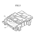
- Fig.5 shows a disc player according to the present invention, which is constructed in the same way as described above.
- a compact disk is put on the carrier table 19, which is pulled out from the casing.
- the pushing-in of the carrier table 19 into the casing will make the disc-loading motor tum, thereby generating a counter electromotive force.
- a cassette or disk player according to the present invention can save significantly the quantity of electric power consumed in the standby mode, in which a minimum quantity of electric power is required for keeping the timer alive and for detecting insertion of a cassette or compact disk by the system control computer.
- the mechanism responsive to insertion of a cassette or compact disk for starting the cassette- or disk-loading motor according to the present invention can be applied to the conventional record player without substantial modification of the software program in the system control computer and other parts.
Landscapes
- Feeding And Guiding Record Carriers (AREA)
- Rotational Drive Of Disk (AREA)
Applications Claiming Priority (2)
| Application Number | Priority Date | Filing Date | Title |
|---|---|---|---|
| JP2000114836 | 2000-04-17 | ||
| JP2000114836A JP3619986B2 (ja) | 2000-04-17 | 2000-04-17 | 記録再生装置 |
Publications (2)
| Publication Number | Publication Date |
|---|---|
| EP1148487A2 true EP1148487A2 (fr) | 2001-10-24 |
| EP1148487A3 EP1148487A3 (fr) | 2003-03-05 |
Family
ID=18626574
Family Applications (1)
| Application Number | Title | Priority Date | Filing Date |
|---|---|---|---|
| EP01109365A Withdrawn EP1148487A3 (fr) | 2000-04-17 | 2001-04-17 | Lecteur de disc/bande magnétique avec dispositif de reduction de la puissance consommeé en mode veille |
Country Status (3)
| Country | Link |
|---|---|
| US (1) | US6590736B2 (fr) |
| EP (1) | EP1148487A3 (fr) |
| JP (1) | JP3619986B2 (fr) |
Families Citing this family (3)
| Publication number | Priority date | Publication date | Assignee | Title |
|---|---|---|---|---|
| JP3792230B2 (ja) * | 2004-01-23 | 2006-07-05 | 松下電器産業株式会社 | メディアドライブおよびコンピュータシステムとメディアドライブ制御方法 |
| JP5473256B2 (ja) * | 2008-06-18 | 2014-04-16 | アルパイン株式会社 | ディスク装置 |
| CN102072881B (zh) * | 2009-11-23 | 2015-03-11 | 阿尔派株式会社 | 盘装置 |
Family Cites Families (12)
| Publication number | Priority date | Publication date | Assignee | Title |
|---|---|---|---|---|
| FR2020174A1 (fr) * | 1968-10-09 | 1970-07-10 | Autovox Spa | |
| US3732546A (en) * | 1971-02-04 | 1973-05-08 | D Ronkin | Information storage and retrieval system |
| JPS55135345A (en) * | 1979-04-06 | 1980-10-22 | Olympus Optical Co Ltd | Method and unit for control for micro cassette tape deck |
| US4445210A (en) * | 1980-06-16 | 1984-04-24 | Victor Company Of Japan, Limited | Tone arm mechanism for a record player |
| JPS5760561A (en) * | 1980-09-29 | 1982-04-12 | Pioneer Electronic Corp | Cassette loader |
| JPH0333979Y2 (fr) * | 1984-09-14 | 1991-07-18 | ||
| DE3702887A1 (de) * | 1987-01-31 | 1988-08-11 | Thomson Brandt Gmbh | Geraet mit einer automatischen einzugsvorrichtung |
| WO1990010973A1 (fr) * | 1989-03-15 | 1990-09-20 | International Business Machines Corporation | Demarrage d'un motor a courant continu sans balais |
| CS274491A3 (en) * | 1990-09-11 | 1992-04-15 | Philips Nv | Recording and/or reproducing apparatus adapted for insertion of a cassette containing a record carrier |
| JPH0855449A (ja) * | 1994-08-11 | 1996-02-27 | Sony Corp | ディスクドライブ装置 |
| JPH1116259A (ja) * | 1997-06-24 | 1999-01-22 | Internatl Business Mach Corp <Ibm> | ヘッド機構制御装置および信号供給制御装置ならびにディスクドライブ装置 |
| KR20010012969A (ko) * | 1998-03-27 | 2001-02-26 | 요트.게.아. 롤페즈 | 구동 모터에 의해 활성화될 수 있는 활성 모드를 갖는기록 및/또는 재생장치 |
-
2000
- 2000-04-17 JP JP2000114836A patent/JP3619986B2/ja not_active Expired - Fee Related
-
2001
- 2001-04-16 US US09/834,930 patent/US6590736B2/en not_active Expired - Fee Related
- 2001-04-17 EP EP01109365A patent/EP1148487A3/fr not_active Withdrawn
Also Published As
| Publication number | Publication date |
|---|---|
| JP2001297499A (ja) | 2001-10-26 |
| US20010030925A1 (en) | 2001-10-18 |
| US6590736B2 (en) | 2003-07-08 |
| JP3619986B2 (ja) | 2005-02-16 |
| EP1148487A3 (fr) | 2003-03-05 |
Similar Documents
| Publication | Publication Date | Title |
|---|---|---|
| US6590736B2 (en) | Tape or disc record player equipped with standby power-saving means | |
| US5119252A (en) | Inhibiting ejection of disc memory for selected time after power off | |
| JPH11149689A (ja) | 情報処理装置 | |
| JPS5923238Y2 (ja) | 操作切換装置 | |
| US4417135A (en) | Power saving electronic counter circuit for tape recorder | |
| KR920001264B1 (ko) | 자기테이프 카세트장치 | |
| EP1744320A2 (fr) | Appareil d'enregistrement/reproduction de disque optique comportant un disque dur | |
| JP2803363B2 (ja) | 摺動接触装置 | |
| JPH06119708A (ja) | 光ディスク装置およびその応用装置 | |
| JP3435565B2 (ja) | 光ディスクの再生装置 | |
| US6023142A (en) | Recording and/or reproducing apparatus having an active mode activable by means of a drive motor | |
| JPS59116959A (ja) | 記録又は再生装置 | |
| SU626438A1 (ru) | Автостоп электропроигрывающего устройства | |
| JPS6057148B2 (ja) | テ−プカウンタ回路 | |
| JPH09213032A (ja) | ポータブルディスク再生装置 | |
| JPH048510Y2 (fr) | ||
| EP0622795B1 (fr) | Equipement muni de mécanisme souple pour la reproduction de bandes enregistrées | |
| JP2944357B2 (ja) | 磁気ディスク装置の駆動方法 | |
| JP3713713B2 (ja) | ディスク状記憶媒体の制動装置 | |
| JP2827392B2 (ja) | 記録再生装置 | |
| JPS6131430Y2 (fr) | ||
| JPS6297194A (ja) | ハ−ドデイスク装置 | |
| KR870002318Y1 (ko) | 캡스턴모우터의 방향전환 제어회로 | |
| KR880001391Y1 (ko) | Vtr 드럼의 이슬맺힘 방지회로 | |
| JPH0325358Y2 (fr) |
Legal Events
| Date | Code | Title | Description |
|---|---|---|---|
| PUAI | Public reference made under article 153(3) epc to a published international application that has entered the european phase |
Free format text: ORIGINAL CODE: 0009012 |
|
| AK | Designated contracting states |
Kind code of ref document: A2 Designated state(s): AT BE CH CY DE DK ES FI FR GB GR IE IT LI LU MC NL PT SE TR |
|
| AX | Request for extension of the european patent |
Free format text: AL;LT;LV;MK;RO;SI |
|
| PUAL | Search report despatched |
Free format text: ORIGINAL CODE: 0009013 |
|
| AK | Designated contracting states |
Kind code of ref document: A3 Designated state(s): AT BE CH CY DE DK ES FI FR GB GR IE IT LI LU MC NL PT SE TR Designated state(s): AT BE CH CY DE DK ES FI FR GB GR IE IT LI LU MC NL PT SE TR |
|
| AX | Request for extension of the european patent |
Extension state: AL LT LV MK RO SI |
|
| RIC1 | Information provided on ipc code assigned before grant |
Ipc: 7G 11B 17/04 B Ipc: 7G 11B 15/675 A |
|
| 17P | Request for examination filed |
Effective date: 20030904 |
|
| 17Q | First examination report despatched |
Effective date: 20031008 |
|
| AKX | Designation fees paid |
Designated state(s): DE GB |
|
| STAA | Information on the status of an ep patent application or granted ep patent |
Free format text: STATUS: THE APPLICATION IS DEEMED TO BE WITHDRAWN |
|
| 18D | Application deemed to be withdrawn |
Effective date: 20040219 |