EP1148637B1 - Circuit d'ajustement de niveau - Google Patents
Circuit d'ajustement de niveau Download PDFInfo
- Publication number
- EP1148637B1 EP1148637B1 EP01303007A EP01303007A EP1148637B1 EP 1148637 B1 EP1148637 B1 EP 1148637B1 EP 01303007 A EP01303007 A EP 01303007A EP 01303007 A EP01303007 A EP 01303007A EP 1148637 B1 EP1148637 B1 EP 1148637B1
- Authority
- EP
- European Patent Office
- Prior art keywords
- level
- adjustment circuit
- level adjustment
- digital
- analog
- Prior art date
- Legal status (The legal status is an assumption and is not a legal conclusion. Google has not performed a legal analysis and makes no representation as to the accuracy of the status listed.)
- Expired - Lifetime
Links
- 230000005236 sound signal Effects 0.000 claims description 20
- 238000006243 chemical reaction Methods 0.000 claims 1
- 230000007423 decrease Effects 0.000 description 5
- 238000001514 detection method Methods 0.000 description 4
- 238000000034 method Methods 0.000 description 4
- 230000015556 catabolic process Effects 0.000 description 3
- 238000007906 compression Methods 0.000 description 3
- 230000006835 compression Effects 0.000 description 3
- 238000006731 degradation reaction Methods 0.000 description 3
- 238000013144 data compression Methods 0.000 description 2
- 238000012986 modification Methods 0.000 description 2
- 230000004048 modification Effects 0.000 description 2
- 230000001052 transient effect Effects 0.000 description 2
- 230000002238 attenuated effect Effects 0.000 description 1
- 238000010586 diagram Methods 0.000 description 1
- 238000001914 filtration Methods 0.000 description 1
- 230000008447 perception Effects 0.000 description 1
Images


Classifications
-
- H—ELECTRICITY
- H03—ELECTRONIC CIRCUITRY
- H03G—CONTROL OF AMPLIFICATION
- H03G3/00—Gain control in amplifiers or frequency changers
- H03G3/02—Manually-operated control
-
- H—ELECTRICITY
- H03—ELECTRONIC CIRCUITRY
- H03G—CONTROL OF AMPLIFICATION
- H03G3/00—Gain control in amplifiers or frequency changers
- H03G3/20—Automatic control
- H03G3/30—Automatic control in amplifiers having semiconductor devices
- H03G3/3089—Control of digital or coded signals
-
- H—ELECTRICITY
- H03—ELECTRONIC CIRCUITRY
- H03G—CONTROL OF AMPLIFICATION
- H03G3/00—Gain control in amplifiers or frequency changers
- H03G3/001—Digital control of analog signals
Definitions
- the present invention relates to a level adjustment circuit for adjusting the signal level of an audio signal, and more particularly for performing both digital level adjustment and analog level adjustment.
- an electronic volume control was thus employed to adjust the output signal level in accordance with a volume control knob or volume control button.
- the electronic volume control adjusts the signal level of the analog audio signal by analog processing in accordance with a volume signal generated from user operation.
- a DSP digital signal processor
- DSP-based digital processing it is also possible to perform signal level adjustment, and the level adjustment is performed by digital processing in accordance with the volume signal.
- WO 99/17442 describes a system in which an analog volume attenuator is used to attenuate an audio signal above a threshold value and a digital volume control is used to attenuate an audio signal below the threshold.
- JP09153748 describes a system in which a digital attenuator attenuates an inputted audio signal with an analog attenuator further attenuating the signal.
- the object of the present invention is to provide a level adjustment circuit capable of performing more preferable level adjustments by combining digital processing and analog processing.
- level adjustment is performed by digital processing for a predetermined low level.
- the level adjustment based on digital processing causes the amount of information to decrease due to data compression, the small amount of data at low level regions hardly poses a problem so that the adjustment by digital processing can be performed without problems.
- part of the level adjustment is performed through digital processing, it is possible to decrease the number of steps for the level adjustment by analog processing, and thus simplify the configuration of the analog level adjustment circuit.
- the level when varying the level, the level is gradually varied in small steps by digital processing. Therefore, noticeably rough sounds are hardly produced when varying the level, and level changes can be performed even when outside the zero cross point. A circuit for zero cross detection becomes unnecessary thereby enabling the circuit configuration to be simplified.
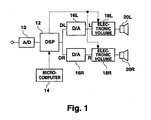
- Fig. 1 is a block diagram showing a configuration of the present embodiment.
- An analog audio signal from various types of sound sources is input by an A/D converter 10.
- the analog audio signal is converted to a digital audio signal, which is input by a DSP 12.
- the digital signal that is output from the A/D converter 10 is, for example, a 24-bit signal.
- various types of processing operations are performed, such as filtering and delay signal superimposition.
- a microcomputer 14 is connected to the DSP 12.
- the microcomputer 14 supplies control signals to the DSP 12 for the various processing operations according to user operation, and the DSP 12 performs the various processing operations on the basis of these control signals.
- the control signals from the microcomputer 14 include a volume signal for controlling the output signal level that is based on volume control operations by the user.
- the DSP 12 performs on the basis of the volume signal a processing operation to adjust the signal level for the digital audio signal that is input. Namely, the DSP 12 attenuates the digital signal by compressing the digital signal in accordance with the amount of attenuation of the audio signal indicated by the volume signal. Namely, attenuation is performed by lowering the value of the digital signal. It should be noted that the number of significant bits decreases after compression. For example, if a 24-bit digital signal is compressed to 16 bits, the result is an attenuation of -48 dB. In the present embodiment, a large attenuation, such as from 0 dB to -48 dB, is not performed at the DSP 12.
- the DSP 12 After performing processing operations including volume adjustment for the digital audio signal, the DSP 12 outputs a digital signal DL for the left channel and a digital signal DR for the right channel.
- the digital signals DL and DR are respectively supplied to D/A converters 16L and 16R, where they are converted to analog signals L and R, then supplied to electronic volume circuits 18L and 18R.
- the electronic volume circuits 18L and 18R perform attenuation for the analog audio signals on the basis of volume signals supplied from the DSP 12. Namely, the DSP 12 performs attenuation through the compression processing of the digital signals in the DSP 12 on a portion of the volume signals supplied from the microcomputer 14 and supplies the volume signals for the remaining attenuation to the electronic volume circuits 18L and 18R. Therefore, the required attenuation is performed in the electronic volume circuits 18L and 18R.
- the electronic volume circuits 18L and 18R can be configured, for example, with resistive potentiometers, to output an analog signal that is attenuated by an amount in accordance with the amount of resistive voltage division. If the level of the analog signal can be adjusted in accordance with the control signal, any form of electronic volume circuit can be employed.
- the attenuation by the electronic volume circuits 18L and 18R only lowers the voltage values with the resistive divider and does not reduce the amount of information by reducing the number of data bits as in digital processing.
- the outputs from the electronic volume circuits 18L and 18R are supplied to speakers 20L and 20R at adjusted volume levels.
- Fig. 2 is a volume-related processing flowchart.
- the DSP 12 first captures (S11) the volume signal from the microcomputer 14.
- various command signals such as for equalization, are received from the microcomputer 14, resulting in the corresponding processing operations to be performed.
- it is judged (S12) whether there is to be a change in the volume signal. If there is to be no change, it is unnecessary to change the volume, and the processing terminates.
- the volume signals generated by the microcomputer sets the maximum attenuation to -80 dB and the number of steps to 82 (1 dB/step, 82 steps for ⁇ ).
- the amount of attenuation in the electronic volume circuits 18L and 18R is set in accordance with the indication in the volume signal and the change up to the set value is performed in 1/5 dB step changes by the DSP 12 (S15).
- the output changes in 1/5 dB increments. As a result, this can prevent noticeably rough sounds from being produced when the volume is varied.
- the amount of attenuation can be changed at a particular timing according to the change in the volume signal and the circuit can be simplified.
- the desired value itself is in 1 dB increments and the amount of attenuation after change is also in 1 dB increments.
- the amount of digital attenuation is changed by the DSP 12 in 1/5 dB increments, and when returning to 0 dB, a 1 dB change is performed at the electronic volume circuits 18L and 18R.
- the data from the DSP 12 is supplied, via D/A converters 16L and 16R and so forth, to the electronic volume circuits 18L and 18R, and on this path a delay is created. Taking this delay into consideration, it is preferable to adjust the timing of the adjustment of the amount of attenuation at the DSP 12 with the adjustment of the amount of attenuation at the electronic volume circuits 18L and 18R.
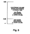
- the volume adjustment in the present embodiment at -X dB and lower was performed by the digital volume control at the DSP 12.
- the -dB mentioned here is limited to a region of considerably low volume, such as -40 dB or -60 dB. At this region, there is hardly any problem in terms of sound perception even if part of the audio data is lost from compression of the digital signal.
- the analog-based adjustment by the electronic volume circuits 18L and 18R and the digital-based transient fine adjustment by the DSP 12 are combined.
- the digital-based adjustment has an extremely small degradation of information (maximum -1 dB attenuation in the example hereinbefore) and the adjustment is transient.
- the volume is adjusted to the desired value, the amount of attenuation by the DSP 12 is 0 dB. Therefore, there is no degradation of information at all.
- the maximum attenuation is -3/5 dB and the degradation of information can be ignored, it is not necessary for the amount of attenuation for the desired value at the DSP 12 to be 0 dB.
- the fine adjustment portion may be assigned to the DSP 12.
- the change in the amount of attenuation can be performed at an arbitrary timing without performing zero cross detection since the amount of attenuation can be gradually varied in small steps set at the DSP 12.
- the adjustments by the electronic volume circuits 18L and 18R use relatively large steps so that the configuration of the electronic volume circuits 18L and 18R can be simplified. For example, in the case using resistive voltage division, when the range of 0 to 40 dB is adjusted in 1/5 dB steps, 200 resistors are necessary. However, if adjusted in 1 dB steps, only 40 resistors are sufficient.
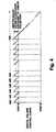
- the 5 step adjustments of 0, -1/5, -2/5, - 3/5, and -4/5 dB are repeated within 1 dB as shown in Fig. 4. Then, from -X dB to - ⁇ , the amount of attenuation increases in 1/5 dB increments. In the transitional period of the volume change, the attenuation adjustment in the DSP 12 is performed.
- both the digital processing in the DSP 12 and the analog processing in the electronic volume circuits 18L and 18R are combined.
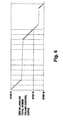
- the signal levels in the electronic volume circuits 18L and 18R are varied in 1 dB increments whereas the signal level is varied in 1/5 dB increments by the DSP 12 when changing the volume. Therefore, the volume changes in 1/5 dB steps as shown in Fig. 6.
Landscapes
- Control Of Amplification And Gain Control (AREA)
- Circuit For Audible Band Transducer (AREA)
- Stereophonic System (AREA)
Claims (2)
- Circuit d'ajustement de niveau destiné à ajuster le niveau de signal d'un signal audio, le circuit d'ajustement de niveau comprenant :un circuit numérique (12) d'ajustement de niveau destiné à effectuer des ajustements de niveau par traitement de signaux audio numériques ;un circuit (16L, 16R) de conversion de numérique en analogique (D/A) destiné à convertir des signaux audio numériques en des signaux audio analogiques ; etun circuit analogique (18L, 18R) d'ajustement de niveau destiné à effectuer des ajustements de niveau par traitement des signaux audio analogiques obtenus ;dans lequel un pas d'ajustement de niveau dans le circuit numérique (12) d'ajustement de niveau est pris plus petit qu'un pas d'ajustement de niveau dans le circuit analogique (18L, 18R) d'ajustement de niveau ; et
dans lequel les ajustements de niveau se font en combinant des ajustements par les pas plus grands du circuit analogique (18L, 18R) d'ajustement de niveau et des ajustements par les pas plus petits du circuit numérique (12) d'ajustement de niveau à l'intérieur des pas plus grands du circuit analogique (18L, 18R) d'ajustement de niveau lorsqu'un signal de volume indiquant un niveau de sortie voulu pour des signaux audio indique un niveau excédant une valeur fixée de niveau bas prédéterminée ; et
les ajustements de niveau sur une plage excédant les grands pas du circuit analogique (18L, 18R) d'ajustement de niveau se font par le circuit numérique d'ajustement de niveau, seul, lorsque le signal de volume indique un niveau de sortie voulu qui est inférieur ou égal à la valeur fixée de niveau bas prédéterminée ;
dans lequel, lorsque le signal de volume indique un niveau excédant la valeur fixée de niveau bas prédéterminée, chaque fois qu'un changement correspondant à un grand pas par le circuit analogique (18L, 18R) d'ajustement de niveau est fait par des petits pas par le circuit numérique (12) d'ajustement de niveau, on change le pas par le circuit analogique (18L, 18R) d'ajustement de niveau et l'on réinitialise la valeur d'ajustement par le circuit numérique (12) d'ajustement de niveau, de façon que les ajustements de niveau appliqués au niveau de sortie indiqué par le signal de volume se fassent par des changements en petits pas faits par le circuit numérique (12) d'ajustement de niveau. - Circuit d'ajustement de niveau selon la revendication 1, dans lequel, lorsque le signal de volume indique un niveau haut excédant la valeur fixée de niveau bas prédéterminée, la valeur d'ajustement par le circuit numérique (12) d'ajustement de niveau est fixée à 0 pour obtenir un niveau final de sortie de sorte que les ajustements de niveau effectués par le circuit numérique (12) d'ajustement de niveau sont utilisés seulement dans un état transitoire.
Applications Claiming Priority (2)
| Application Number | Priority Date | Filing Date | Title |
|---|---|---|---|
| JP2000094331 | 2000-03-30 | ||
| JP2000094331A JP3889546B2 (ja) | 2000-03-30 | 2000-03-30 | レベル調整回路 |
Publications (3)
| Publication Number | Publication Date |
|---|---|
| EP1148637A2 EP1148637A2 (fr) | 2001-10-24 |
| EP1148637A3 EP1148637A3 (fr) | 2003-09-10 |
| EP1148637B1 true EP1148637B1 (fr) | 2007-05-09 |
Family
ID=18609396
Family Applications (1)
| Application Number | Title | Priority Date | Filing Date |
|---|---|---|---|
| EP01303007A Expired - Lifetime EP1148637B1 (fr) | 2000-03-30 | 2001-03-29 | Circuit d'ajustement de niveau |
Country Status (7)
| Country | Link |
|---|---|
| US (1) | US7110557B2 (fr) |
| EP (1) | EP1148637B1 (fr) |
| JP (1) | JP3889546B2 (fr) |
| KR (1) | KR100496373B1 (fr) |
| CN (1) | CN1332519A (fr) |
| DE (1) | DE60128289T2 (fr) |
| TW (1) | TW515994B (fr) |
Families Citing this family (19)
| Publication number | Priority date | Publication date | Assignee | Title |
|---|---|---|---|---|
| US20060014697A1 (en) | 2001-08-22 | 2006-01-19 | Travis Mickle | Pharmaceutical compositions for prevention of overdose or abuse |
| JP3526850B2 (ja) * | 2002-03-26 | 2004-05-17 | 沖電気工業株式会社 | 音声出力装置 |
| US7539614B2 (en) * | 2003-11-14 | 2009-05-26 | Nxp B.V. | System and method for audio signal processing using different gain factors for voiced and unvoiced phonemes |
| WO2005091671A1 (fr) * | 2004-03-19 | 2005-09-29 | Pioneer Corporation | Methode de commande de volume, commande de volume, programme de commande de volume, appareil electronique |
| US20070189544A1 (en) * | 2005-01-15 | 2007-08-16 | Outland Research, Llc | Ambient sound responsive media player |
| JPWO2006106672A1 (ja) * | 2005-03-31 | 2008-09-11 | パイオニア株式会社 | 増幅装置および情報処理装置 |
| US20060247811A1 (en) * | 2005-05-02 | 2006-11-02 | Texas Instruments Incorporated | Batch processing control of volume events in a digital amplifier environment |
| CN1953047B (zh) * | 2005-10-21 | 2010-06-23 | 英华达(南京)科技有限公司 | 音量范围调整系统及其方法 |
| KR100857086B1 (ko) * | 2006-10-09 | 2008-09-05 | 엘지전자 주식회사 | 오디오 볼륨 레벨 설정 방법 |
| US8135147B2 (en) * | 2006-10-09 | 2012-03-13 | Lg Electronics Inc. | Method and device for adjusting audio volume level |
| JP4948202B2 (ja) * | 2007-02-23 | 2012-06-06 | アルパイン株式会社 | 音声出力装置、制御プログラム及びコンピュータ読み取り可能な記録媒体 |
| US8369540B2 (en) * | 2007-05-30 | 2013-02-05 | Nxp B.V. | Audio signal amplification |
| CN101350604B (zh) * | 2007-07-19 | 2012-07-04 | 鸿富锦精密工业(深圳)有限公司 | 自动切换音量调节模式的装置及方法 |
| DK2346271T3 (da) * | 2009-12-01 | 2014-08-04 | Oticon As | Styring af betjeningsparametre i et binauralt lyttesystem |
| JP2011160031A (ja) * | 2010-01-29 | 2011-08-18 | Ricoh Co Ltd | 音声音楽再生装置 |
| DE102010036207A1 (de) * | 2010-08-31 | 2012-03-01 | Siemens Aktiengesellschaft | Schalter, insbesondere Leistungsschalter für Niederspannungen |
| CN104242848B (zh) * | 2013-06-21 | 2016-12-28 | 普诚科技股份有限公司 | 增益控制系统、声音播放系统及其增益控制的方法 |
| JP7106913B2 (ja) * | 2018-03-22 | 2022-07-27 | ヤマハ株式会社 | 音響機器、音響制御システム、音響制御方法、及びプログラム |
| CN113747309A (zh) * | 2020-05-27 | 2021-12-03 | 阿里巴巴集团控股有限公司 | 音频处理方法、链路和设备 |
Family Cites Families (8)
| Publication number | Priority date | Publication date | Assignee | Title |
|---|---|---|---|---|
| US5323275A (en) * | 1991-01-31 | 1994-06-21 | Sony Corporation | Digital signal recording and/or reproducing apparatus having correlated digital and analog signal level controllers |
| JPH05198092A (ja) | 1992-01-20 | 1993-08-06 | Sony Corp | レベルコントロール回路 |
| US5394476A (en) | 1992-12-17 | 1995-02-28 | Motorola, Inc. | Volume control device |
| JPH07240647A (ja) | 1994-02-28 | 1995-09-12 | Fujitsu Ten Ltd | 音響再生装置 |
| GB2297443B (en) | 1995-01-26 | 1999-09-08 | Sony Uk Ltd | Amplifier |
| JPH09153748A (ja) | 1995-11-30 | 1997-06-10 | Sharp Corp | 音量可変装置 |
| US6317502B1 (en) * | 1996-02-29 | 2001-11-13 | Sanyo Electric Co., Ltd. | Electronic volume control circuit with controlled output characteristic |
| US6088461A (en) | 1997-09-26 | 2000-07-11 | Crystal Semiconductor Corporation | Dynamic volume control system |
-
2000
- 2000-03-30 JP JP2000094331A patent/JP3889546B2/ja not_active Expired - Fee Related
-
2001
- 2001-03-12 TW TW090105716A patent/TW515994B/zh not_active IP Right Cessation
- 2001-03-26 US US09/818,249 patent/US7110557B2/en not_active Expired - Lifetime
- 2001-03-29 KR KR10-2001-0016468A patent/KR100496373B1/ko not_active Expired - Fee Related
- 2001-03-29 EP EP01303007A patent/EP1148637B1/fr not_active Expired - Lifetime
- 2001-03-29 DE DE60128289T patent/DE60128289T2/de not_active Expired - Lifetime
- 2001-03-30 CN CN01117886A patent/CN1332519A/zh active Pending
Also Published As
| Publication number | Publication date |
|---|---|
| KR20010095091A (ko) | 2001-11-03 |
| JP3889546B2 (ja) | 2007-03-07 |
| CN1332519A (zh) | 2002-01-23 |
| DE60128289D1 (de) | 2007-06-21 |
| DE60128289T2 (de) | 2008-01-10 |
| JP2001285983A (ja) | 2001-10-12 |
| EP1148637A3 (fr) | 2003-09-10 |
| TW515994B (en) | 2003-01-01 |
| EP1148637A2 (fr) | 2001-10-24 |
| KR100496373B1 (ko) | 2005-06-21 |
| US20010026624A1 (en) | 2001-10-04 |
| US7110557B2 (en) | 2006-09-19 |
Similar Documents
| Publication | Publication Date | Title |
|---|---|---|
| EP1148637B1 (fr) | Circuit d'ajustement de niveau | |
| US6252969B1 (en) | Howling detection and prevention circuit and a loudspeaker system employing the same | |
| US5255324A (en) | Digitally controlled audio amplifier with voltage limiting | |
| US4908855A (en) | Electronic telephone terminal having noise suppression function | |
| KR100744847B1 (ko) | 입력장치,재생장치 및 볼륨조정방법 | |
| US20050207594A1 (en) | Sound signal processing apparatus and sound signal processing method | |
| US8611572B2 (en) | Device and method for controlling the step size of an adaptive filter | |
| US7315625B2 (en) | Sound apparatus, method of changing sound characteristics, and data recording medium on which a sound correction program | |
| KR930001295B1 (ko) | 이득 조절기 | |
| US20110200209A1 (en) | Level adjusting circuit | |
| US10630252B2 (en) | Audio signal processor and method of processing audio signal | |
| JP2946884B2 (ja) | 低音域特性補正回路 | |
| JP2009100272A (ja) | 音量制御装置、プログラム、及び音量制御方法 | |
| EP1263132B1 (fr) | Dispositif atténuateur variable de signaux | |
| JP2636897B2 (ja) | ハンドフリー通話回路 | |
| JPS61278217A (ja) | Fmステレオ受信機 | |
| KR19990041228A (ko) | 이퀄라이즈 기능을 구비한 오디오 기기의 자동 음량조정장치 | |
| JP3815836B2 (ja) | オーディオ信号増幅回路 | |
| CN121710849A (zh) | 音频信号处理方法及装置、电子设备、存储介质 | |
| JPH0519843B2 (fr) | ||
| JPH0256155A (ja) | ハウリング防止装置 | |
| JP3202902B2 (ja) | ノイズ抑圧装置 | |
| JPH09284073A (ja) | 自動利得制御回路 | |
| JPH0646490A (ja) | ハウリング防止プロセッサ | |
| JPH03128511A (ja) | 自動ミキサ装置 |
Legal Events
| Date | Code | Title | Description |
|---|---|---|---|
| PUAI | Public reference made under article 153(3) epc to a published international application that has entered the european phase |
Free format text: ORIGINAL CODE: 0009012 |
|
| AK | Designated contracting states |
Kind code of ref document: A2 Designated state(s): AT BE CH CY DE DK ES FI FR GB GR IE IT LI LU MC NL PT SE TR |
|
| AX | Request for extension of the european patent |
Free format text: AL;LT;LV;MK;RO;SI |
|
| RIN1 | Information on inventor provided before grant (corrected) |
Inventor name: UCHINO, TAKASHI Inventor name: MASUMOTO, TAKAHIKO Inventor name: KON, YSHIHIKO Inventor name: KANEKO, HIROSHI |
|
| PUAL | Search report despatched |
Free format text: ORIGINAL CODE: 0009013 |
|
| AK | Designated contracting states |
Kind code of ref document: A3 Designated state(s): AT BE CH CY DE DK ES FI FR GB GR IE IT LI LU MC NL PT SE TR |
|
| AX | Request for extension of the european patent |
Extension state: AL LT LV MK RO SI |
|
| 17P | Request for examination filed |
Effective date: 20040301 |
|
| AKX | Designation fees paid |
Designated state(s): DE FR GB IT NL |
|
| 17Q | First examination report despatched |
Effective date: 20040804 |
|
| GRAP | Despatch of communication of intention to grant a patent |
Free format text: ORIGINAL CODE: EPIDOSNIGR1 |
|
| RIN1 | Information on inventor provided before grant (corrected) |
Inventor name: KON, YOSHIHIKO Inventor name: MASUMOTO, TAKAHIKO Inventor name: KANEKO, HIROSHI Inventor name: UCHINO, TAKASHI |
|
| GRAS | Grant fee paid |
Free format text: ORIGINAL CODE: EPIDOSNIGR3 |
|
| GRAA | (expected) grant |
Free format text: ORIGINAL CODE: 0009210 |
|
| AK | Designated contracting states |
Kind code of ref document: B1 Designated state(s): DE FR GB IT NL |
|
| REG | Reference to a national code |
Ref country code: GB Ref legal event code: FG4D |
|
| RIN1 | Information on inventor provided before grant (corrected) |
Inventor name: KON, YOSHIHIKO Inventor name: MASUMOTO, TAKAHIKO Inventor name: KANEKO, HIROSHI Inventor name: UCHINO, TAKASHI |
|
| REF | Corresponds to: |
Ref document number: 60128289 Country of ref document: DE Date of ref document: 20070621 Kind code of ref document: P |
|
| ET | Fr: translation filed | ||
| PLBE | No opposition filed within time limit |
Free format text: ORIGINAL CODE: 0009261 |
|
| STAA | Information on the status of an ep patent application or granted ep patent |
Free format text: STATUS: NO OPPOSITION FILED WITHIN TIME LIMIT |
|
| 26N | No opposition filed |
Effective date: 20080212 |
|
| PGFP | Annual fee paid to national office [announced via postgrant information from national office to epo] |
Ref country code: FR Payment date: 20120328 Year of fee payment: 12 |
|
| PGFP | Annual fee paid to national office [announced via postgrant information from national office to epo] |
Ref country code: GB Payment date: 20120227 Year of fee payment: 12 Ref country code: IT Payment date: 20120323 Year of fee payment: 12 |
|
| PGFP | Annual fee paid to national office [announced via postgrant information from national office to epo] |
Ref country code: DE Payment date: 20120330 Year of fee payment: 12 Ref country code: NL Payment date: 20120322 Year of fee payment: 12 |
|
| REG | Reference to a national code |
Ref country code: NL Ref legal event code: V1 Effective date: 20131001 |
|
| GBPC | Gb: european patent ceased through non-payment of renewal fee |
Effective date: 20130329 |
|
| REG | Reference to a national code |
Ref country code: FR Ref legal event code: ST Effective date: 20131129 |
|
| REG | Reference to a national code |
Ref country code: DE Ref legal event code: R119 Ref document number: 60128289 Country of ref document: DE Effective date: 20131001 |
|
| PG25 | Lapsed in a contracting state [announced via postgrant information from national office to epo] |
Ref country code: FR Free format text: LAPSE BECAUSE OF NON-PAYMENT OF DUE FEES Effective date: 20130402 Ref country code: GB Free format text: LAPSE BECAUSE OF NON-PAYMENT OF DUE FEES Effective date: 20130329 Ref country code: DE Free format text: LAPSE BECAUSE OF NON-PAYMENT OF DUE FEES Effective date: 20131001 |
|
| PG25 | Lapsed in a contracting state [announced via postgrant information from national office to epo] |
Ref country code: IT Free format text: LAPSE BECAUSE OF NON-PAYMENT OF DUE FEES Effective date: 20130329 Ref country code: NL Free format text: LAPSE BECAUSE OF NON-PAYMENT OF DUE FEES Effective date: 20131001 |