EP1149714A2 - Verfahren zur Montage eines radialen Fahrzeugreifens - Google Patents
Verfahren zur Montage eines radialen Fahrzeugreifens Download PDFInfo
- Publication number
- EP1149714A2 EP1149714A2 EP01303595A EP01303595A EP1149714A2 EP 1149714 A2 EP1149714 A2 EP 1149714A2 EP 01303595 A EP01303595 A EP 01303595A EP 01303595 A EP01303595 A EP 01303595A EP 1149714 A2 EP1149714 A2 EP 1149714A2
- Authority
- EP
- European Patent Office
- Prior art keywords
- tire
- cord
- pair
- belt
- members
- Prior art date
- Legal status (The legal status is an assumption and is not a legal conclusion. Google has not performed a legal analysis and makes no representation as to the accuracy of the status listed.)
- Granted
Links
- 238000000034 method Methods 0.000 title claims abstract description 23
- 229910000831 Steel Inorganic materials 0.000 claims description 12
- 239000010959 steel Substances 0.000 claims description 12
- 239000000835 fiber Substances 0.000 claims description 10
- 238000004804 winding Methods 0.000 claims description 8
- 230000001154 acute effect Effects 0.000 claims description 6
- 239000011324 bead Substances 0.000 description 6
- 238000011156 evaluation Methods 0.000 description 6
- 239000000463 material Substances 0.000 description 5
- 230000009471 action Effects 0.000 description 4
- 230000000052 comparative effect Effects 0.000 description 4
- 239000004760 aramid Substances 0.000 description 3
- 229920003235 aromatic polyamide Polymers 0.000 description 3
- 230000000694 effects Effects 0.000 description 3
- 230000006872 improvement Effects 0.000 description 3
- 238000005452 bending Methods 0.000 description 2
- 230000015556 catabolic process Effects 0.000 description 2
- 230000008859 change Effects 0.000 description 2
- 238000006731 degradation reaction Methods 0.000 description 2
- 230000009021 linear effect Effects 0.000 description 2
- 230000004044 response Effects 0.000 description 2
- CYJRNFFLTBEQSQ-UHFFFAOYSA-N 8-(3-methyl-1-benzothiophen-5-yl)-N-(4-methylsulfonylpyridin-3-yl)quinoxalin-6-amine Chemical compound CS(=O)(=O)C1=C(C=NC=C1)NC=1C=C2N=CC=NC2=C(C=1)C=1C=CC2=C(C(=CS2)C)C=1 CYJRNFFLTBEQSQ-UHFFFAOYSA-N 0.000 description 1
- 239000004953 Aliphatic polyamide Substances 0.000 description 1
- 229920001875 Ebonite Polymers 0.000 description 1
- 239000004677 Nylon Substances 0.000 description 1
- 229920000297 Rayon Polymers 0.000 description 1
- 229920003231 aliphatic polyamide Polymers 0.000 description 1
- 230000001276 controlling effect Effects 0.000 description 1
- 239000000945 filler Substances 0.000 description 1
- 238000012423 maintenance Methods 0.000 description 1
- 230000007935 neutral effect Effects 0.000 description 1
- 229920001778 nylon Polymers 0.000 description 1
- 229920003207 poly(ethylene-2,6-naphthalate) Polymers 0.000 description 1
- 229920000728 polyester Polymers 0.000 description 1
- 239000011112 polyethylene naphthalate Substances 0.000 description 1
- 229920000139 polyethylene terephthalate Polymers 0.000 description 1
- 239000005020 polyethylene terephthalate Substances 0.000 description 1
- 239000002964 rayon Substances 0.000 description 1
- 230000009467 reduction Effects 0.000 description 1
- 229920005989 resin Polymers 0.000 description 1
- 239000011347 resin Substances 0.000 description 1
Images




Classifications
-
- B—PERFORMING OPERATIONS; TRANSPORTING
- B60—VEHICLES IN GENERAL
- B60C—VEHICLE TYRES; TYRE INFLATION; TYRE CHANGING; CONNECTING VALVES TO INFLATABLE ELASTIC BODIES IN GENERAL; DEVICES OR ARRANGEMENTS RELATED TO TYRES
- B60C19/00—Tyre parts or constructions not otherwise provided for
- B60C19/001—Tyres requiring an asymmetric or a special mounting
-
- B—PERFORMING OPERATIONS; TRANSPORTING
- B60—VEHICLES IN GENERAL
- B60C—VEHICLE TYRES; TYRE INFLATION; TYRE CHANGING; CONNECTING VALVES TO INFLATABLE ELASTIC BODIES IN GENERAL; DEVICES OR ARRANGEMENTS RELATED TO TYRES
- B60C9/00—Reinforcements or ply arrangement of pneumatic tyres
- B60C9/18—Structure or arrangement of belts or breakers, crown-reinforcing or cushioning layers
- B60C9/20—Structure or arrangement of belts or breakers, crown-reinforcing or cushioning layers built-up from rubberised plies each having all cords arranged substantially parallel
- B60C9/2003—Structure or arrangement of belts or breakers, crown-reinforcing or cushioning layers built-up from rubberised plies each having all cords arranged substantially parallel characterised by the materials of the belt cords
- B60C9/2009—Structure or arrangement of belts or breakers, crown-reinforcing or cushioning layers built-up from rubberised plies each having all cords arranged substantially parallel characterised by the materials of the belt cords comprising plies of different materials
-
- B—PERFORMING OPERATIONS; TRANSPORTING
- B60—VEHICLES IN GENERAL
- B60C—VEHICLE TYRES; TYRE INFLATION; TYRE CHANGING; CONNECTING VALVES TO INFLATABLE ELASTIC BODIES IN GENERAL; DEVICES OR ARRANGEMENTS RELATED TO TYRES
- B60C9/00—Reinforcements or ply arrangement of pneumatic tyres
- B60C9/18—Structure or arrangement of belts or breakers, crown-reinforcing or cushioning layers
- B60C9/20—Structure or arrangement of belts or breakers, crown-reinforcing or cushioning layers built-up from rubberised plies each having all cords arranged substantially parallel
- B60C9/22—Structure or arrangement of belts or breakers, crown-reinforcing or cushioning layers built-up from rubberised plies each having all cords arranged substantially parallel the plies being arranged with all cords disposed along the circumference of the tyre
- B60C9/2204—Structure or arrangement of belts or breakers, crown-reinforcing or cushioning layers built-up from rubberised plies each having all cords arranged substantially parallel the plies being arranged with all cords disposed along the circumference of the tyre obtained by circumferentially narrow strip winding
-
- B—PERFORMING OPERATIONS; TRANSPORTING
- B60—VEHICLES IN GENERAL
- B60C—VEHICLE TYRES; TYRE INFLATION; TYRE CHANGING; CONNECTING VALVES TO INFLATABLE ELASTIC BODIES IN GENERAL; DEVICES OR ARRANGEMENTS RELATED TO TYRES
- B60C9/00—Reinforcements or ply arrangement of pneumatic tyres
- B60C9/18—Structure or arrangement of belts or breakers, crown-reinforcing or cushioning layers
- B60C9/20—Structure or arrangement of belts or breakers, crown-reinforcing or cushioning layers built-up from rubberised plies each having all cords arranged substantially parallel
- B60C2009/2041—Structure or arrangement of belts or breakers, crown-reinforcing or cushioning layers built-up from rubberised plies each having all cords arranged substantially parallel with an interrupted belt ply, e.g. using two or more portions of the same ply
-
- Y—GENERAL TAGGING OF NEW TECHNOLOGICAL DEVELOPMENTS; GENERAL TAGGING OF CROSS-SECTIONAL TECHNOLOGIES SPANNING OVER SEVERAL SECTIONS OF THE IPC; TECHNICAL SUBJECTS COVERED BY FORMER USPC CROSS-REFERENCE ART COLLECTIONS [XRACs] AND DIGESTS
- Y10—TECHNICAL SUBJECTS COVERED BY FORMER USPC
- Y10S—TECHNICAL SUBJECTS COVERED BY FORMER USPC CROSS-REFERENCE ART COLLECTIONS [XRACs] AND DIGESTS
- Y10S152/00—Resilient tires and wheels
- Y10S152/904—Specified tread pattern for front tyre and rear tyre
-
- Y—GENERAL TAGGING OF NEW TECHNOLOGICAL DEVELOPMENTS; GENERAL TAGGING OF CROSS-SECTIONAL TECHNOLOGIES SPANNING OVER SEVERAL SECTIONS OF THE IPC; TECHNICAL SUBJECTS COVERED BY FORMER USPC CROSS-REFERENCE ART COLLECTIONS [XRACs] AND DIGESTS
- Y10—TECHNICAL SUBJECTS COVERED BY FORMER USPC
- Y10T—TECHNICAL SUBJECTS COVERED BY FORMER US CLASSIFICATION
- Y10T152/00—Resilient tires and wheels
- Y10T152/10—Tires, resilient
- Y10T152/10495—Pneumatic tire or inner tube
- Y10T152/10765—Characterized by belt or breaker structure
-
- Y—GENERAL TAGGING OF NEW TECHNOLOGICAL DEVELOPMENTS; GENERAL TAGGING OF CROSS-SECTIONAL TECHNOLOGIES SPANNING OVER SEVERAL SECTIONS OF THE IPC; TECHNICAL SUBJECTS COVERED BY FORMER USPC CROSS-REFERENCE ART COLLECTIONS [XRACs] AND DIGESTS
- Y10—TECHNICAL SUBJECTS COVERED BY FORMER USPC
- Y10T—TECHNICAL SUBJECTS COVERED BY FORMER US CLASSIFICATION
- Y10T152/00—Resilient tires and wheels
- Y10T152/10—Tires, resilient
- Y10T152/10495—Pneumatic tire or inner tube
- Y10T152/10765—Characterized by belt or breaker structure
- Y10T152/10801—Structure made up of two or more sets of plies wherein the reinforcing cords in one set lie in a different angular position relative to those in other sets
-
- Y—GENERAL TAGGING OF NEW TECHNOLOGICAL DEVELOPMENTS; GENERAL TAGGING OF CROSS-SECTIONAL TECHNOLOGIES SPANNING OVER SEVERAL SECTIONS OF THE IPC; TECHNICAL SUBJECTS COVERED BY FORMER USPC CROSS-REFERENCE ART COLLECTIONS [XRACs] AND DIGESTS
- Y10—TECHNICAL SUBJECTS COVERED BY FORMER USPC
- Y10T—TECHNICAL SUBJECTS COVERED BY FORMER US CLASSIFICATION
- Y10T29/00—Metal working
- Y10T29/49—Method of mechanical manufacture
- Y10T29/49826—Assembling or joining
Definitions
- This invention relates to a pneumatic radial tire capable of making optimum a deformation and a resistance force of the tire in correspondence to a difference between external forces respectively acting to a front tire and a rear tire and more particularly to a method of mounting a pneumatic radial tire suitable for use in motorcycles and the like.
- a mounting structure that tires having only a spiral belt are mounted onto a front wheel and a rear wheel of a motorcycle, respectively, and a mounting structure that a tire having a combination of a spiral belt with a pair of cross belt members containing cords therein, the cords of which members being crossed with each other, is used only in either a front wheel or a rear wheel of a motorcycle.
- a pneumatic radial tire comprising a spiral belt formed by spirally winding a cord along a circumferential direction of a crown portion of the tire, and a pair of cross belt members arranged in parallel to each other at both sides of an equatorial plane of the tire and at a given opening space, cords of which members being extended at a given cord angle in opposite directions to each other with respect to the equatorial plane, an improvement wherein the tire is mounted as a front tire such that the pair of cross belt members are arranged so as to finally contact a portion of the cord in the belt member facing the opening space with ground in a forward rotating direction of the tire.
- the action of the above mounting method is described below. That is, when the above tire is mounted on a front wheel of a vehicle such as motorcycle or the like, the pair of the cross belt members in the tire are arranged so as to finally contact a portion of the cord in the belt member facing the opening space with ground in a forward rotating direction of the tire.
- the inclinations of the cords in the cross belt members are so-called inverted herringbone form that the portion of the cord in the belt member facing to the opening space finally contact with ground in the forward running direction of the tire or a positive rotating direction thereof. Therefore, by mounting the above tire as a front tire so as to render the cord inclinations in the pair of the cross belt members into the inverted herringbone form, the deformation and resistance force of the tire are made optimum against external force acting to the front tire.
- a pneumatic radial tire comprising a spiral belt formed by spirally winding a cord along a circumferential direction of a crown portion of the tire, and a pair of cross belt members arranged in parallel to each other at both sides of an equatorial plane of the tire and at a given opening space, cords of which members being extended at a given cord angle in opposite directions to each other with respect to the equatorial plane, an improvement wherein the tire is mounted as a rear tire such that the pair of cross belt members are arranged so as to firstly contact a portion of the cord in the belt member facing the opening space with ground in a forward rotating direction of the tire.
- the action of the above mounting method is described below. That is, when the above tire is mounted onto a rear wheel of a vehicle such as motorcycle or the like, the pair of the cross belt members in the tire are arranged so as to firstly contact a portion of the cord in the belt member facing the opening space with ground in a forward rotating direction of the tire.
- the inclinations of the cords in the cross belt members are so-called herringbone form that the portion of the cord in the belt member facing to the opening space firstly contact with ground in the forward running direction of the tire or a positive rotating direction thereof. Therefore, by mounting the above tire as a rear tire so as to render the cord inclinations in the pair of the cross belt members into the herringbone form, the deformation and resistance force of the tire are made optimum against external force acting to the rear tire.
- a pneumatic radial tire comprising a spiral belt formed by spirally winding a cord along a circumferential direction of a crown portion of the tire, and a pair of cross belt members arranged in parallel to each other at both sides of an equatorial plane of the tire and at a given opening space, cords of which members being extended at a given cord angle in opposite directions to each other with respect to the equatorial plane, an improvement wherein the tire is mounted as a front tire such that the pair of cross belt members are arranged so as to finally contact a portion of the cord in the belt member facing the opening space with ground in a forward rotating direction of the tire and another tire is mounted as a rear tire such that the pair of cross belt members are arranged so as to firstly contact a portion of the cord in the belt member facing the opening space with ground in a forward rotating direction of the tire.
- the action of the above mounting method is described below. That is, when the pair of the front and rear tires are mounted onto front and rear wheels of a vehicle such as motorcycle or the like, by mounting one of the above tires as a front tire so as to render the cord inclinations in the pair of the cross belt members into the inverted herringbone form and the other tire as a rear tire so as to render the cord inclinations in the pair of the cross belt members into the herringbone form, the deformation and resistance force of the tire are made optimum in correspondence to the difference between external forces respectively acting to the front tire and the rear tire.
- the rigidity required as the tire can effectively be ensured with respect to input of the external forces to the radial direction and lateral direction of the tire acting to the front and rear tires at each state of the straight running and the cornering.
- the external force acting to the front wheel in the braking and the external force acting to the rear wheel in the traction differ with each other in the input direction of the external force, but by making the cord inclinations of the belt members in the front tire opposite to those in the rear tire can effectively be ensured the rigidity required as the tire against these external forces.
- a steel cord having an initial tensile strength of no less than 50cN/cord is used in any one of the spiral belt and the pair of the cross belt members. That is, when the steel cords having an initial tensile strength of no less than 50cN/cord are applied to any one of the spiral belt and the cross belt member, the rigidity required as the tire can effectively be ensured and is possible to cope with external forces applied from various directions.
- a organic fiber cord having an initial tensile strength of no less than 50cN/cord is used in any one of the spiral belt and the pair of the cross belt members. That is, when the organic fiber cords having an initial tensile strength of no less than 50cN/cord are applied to any one of the spiral belt and the cross belt member, the rigidity required as the tire can effectively be ensured and is possible to cope with external forces applied from various directions.
- the spiral belt and the cross belt member may be constituted by combining the steel cord and the organic fiber cord.
- the spiral belt is made of the steel cords and each of the pair of cross belt members is made of the organic fiber_cords and a combination that the spiral belt is made of the organic fiber cords and each of the pair of cross belt members is made of the steel cords.
- the pair of cross belt members are arranged at the spiral belt as an outer layer or an inner layer so as to make an angle of the cord constituting each belt member with respect to the equatorial plane within a range of 80-20° as measured at the side of an acute angle, and a total width of the pair of cross belt members including the opening space is 150-70% of a tread width and a width of the opening space is 1-50 mm.
- the angle of the cord constituting each cross belt member with respect to the equatorial plane exceeds 80°, the rigidity as the tire is not sufficiently ensured, while when the angle is less than 20°, the step difference of the rigidity between the presence and the absence of the cross belt member pair becomes too large and the linear property of cornering force with respect to the camber angle is damaged. Therefore, the angle is restricted to a range of 80-20°.
- the total width of the pair of cross belt members is less than 70% of the tread width, the rigidity required as the tire can not be ensured, while when the total width exceeds 150% of the tread width, the rigidity as the tire becomes too high and the degradation of the vibration absorptivity is caused, so that the total width is restricted to a range of 150-70%.
- the width of the opening space between the pair of cross belt members is less than 1 mm, the opening space is too small and the bending rigidity in the vicinity of the center of the crown portion becomes too high, so that the ride comfort is degraded. While, when the width of the opening space exceeds 50 mm, the effect of ensuring the rigidity required as the tire is substantially lost. Therefore, the width of the opening space between the pair of cross belt members is restricted to a range of 1-50 mm.
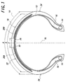
- a first embodiment of the pneumatic radial tire according to the invention is described with reference to Figs. 1 to 3.
- Fig. 1 a motorcycle tire 10 of radial structure as the first embodiment of the pneumatic radial tire according to the invention.
- a carcass 12 constituting a skeleton of the tire 10 is formed by a plurality of plies (not shown) each containing cords such as polyester cord or the like arranged in a direction crossing with an equatorial plane CL of the tire 10.
- a pair of bead cores 14 each formed by winding and bundling steel wires in a ring shape are arranged in the vicinity of both end portions of the carcass 12, and both the end portions of the carcass 12 are wound around these bead cores 14, respectively. Furthermore, a tapered bead filler 16 made of a hard rubber is embedded between the carcass 12 and a turnup portion thereof above the bead core 14.
- the carcass 12 is extended between the pair of the bead cores 14 and embedded in a rubber material forming a crown portion 18 of the tire 10 through a sidewall portion 24 of the tire 10 connecting the bead core 14 to the crown portion 18.
- the equatorial plane CL extends along the circumferential direction of the crown portion 18 so as to divide the tire 10 in half.
- a tread 22 made of a rubber material as an envelope contacting with a road face is arranged side a ground contact face of the crown portion 18 and a tread pattern having ribs defined by a plurality of grooves is formed on the tread 22.
- an innerliner (not shown) is arranged as an innermost layer of the tire 10.
- a spiral belt 26 being a monospiral belt formed by spirally winging a cord along the circumferential direction of the crown portion 18 is embedded in the rubber material forming the crown portion 18 at the outer circumferential side of the carcass 12, and a pair of cross belt members 28A, 28B extending in parallel to each other are arranged on the outer circumferential side of the spiral belt 26 at both sides of the equatorial plane CL of the tire, respectively.
- a total width A of the pair of cross belt members 28A, 28B including an opening space 32 formed therebetween is set within a range of 150-70% of a width B of the tread 22 as measured along an arc of the tire surface, and a width C of the opening space 32 between the pair of cross belt members 28A, 28B is set to a range of 1-50 mm.
- cords constituting the pair of cross belt members 28A, 28B extend at a symmetrical inclination angle with respect to the equatorial plane CL of the tire in directions opposite to each other.
- an angle ⁇ between the cord and the equatorial plane CL as measured at an acute angle side is made to 80-20°.
- a steel cord or a organic fiber cord having an initial tensile strength of no less than 50cN per cord is used as the cord constituting each of the spiral belt 26 and the cross belt members 28A, 28B.
- the pair of cross belt members 28A, 28B are arranged so as to finally contact a portion of the cord in the belt member facing the opening space 32 with ground in a forward rotating direction of the tire (direction by an arrow Z in Fig. 2), whereby the tire 10 is mounted so that an angle ⁇ 1 of the cord in the cross belt members 28A, 28B with respect to the equatorial plane CL is an acute angle.
- the pair of cross belt members 28A, 28B are arranged so as to firstly contact a portion of the cord in the belt member facing the opening space 32 with ground in a forward rotating direction of the tire (direction by an arrow Z in Fig. 3), whereby the tire 10 is mounted so that an angle ⁇ 2 of the cord in the cross belt members 28A, 28B with respect to the equatorial plane CL is an obtuse angle.
- the term "forward rotating direction of tire” used herein means the rotating direction of the tire 10 when the motorcycle goes forward.
- the spiral belt 26 formed by spirally winding the cord along the circumferential direction of the crown portion 18 is arranged, but also the pair of cross belt members 28A, 28B containing cords extended at an angle opposite to each other with respect to the equatorial plane CL of the tire are arranged at the outside of the spiral belt 26 and on both sides of the equatorial plane CL in parallel to each other and at a given opening space 32. And also, the angle ⁇ of the cord constituting each of the cross belt members 28A, 28B with respect to the equatorial plane CL is made to 80-20° as measured at the acute angle side.
- the angle ⁇ of the cord constituting each of the cross belt members 28A, 28B with respect to the equatorial plane CL in the tire exceeds 80°, the rigidity of the tire is not sufficient ensured, while when the angle ⁇ is less than 20°, the step difference of the rigidity between the presence and the absence of the cross belt members 28A, 28B becomes too large and hence the linear property to a change of a camber is damaged. Therefore, the angle ⁇ is restricted to a range of 80-20°.
- the tire 10 is mounted as a front tire such that the pair of cross belt members 28A, 28B are arranged so as to finally contact a portion of the cord in the belt member facing the opening space 32 with ground in a forward rotating direction of the tire to thereby render the angle ⁇ 1 of the cord in the cross belt members 28A, 28B with respect to the equatorial plane CL into an acute angle as shown in Fig. 2.
- the tire 10 is mounted as a rear tire such that the pair of cross belt members 28A, 28B are arranged so as to firstly contact a portion of the cord in the belt member facing the opening space 32 with ground in a forward rotating direction of the tire to thereby render the angle ⁇ 2 of the cord in the cross belt members 28A, 28B with respect to the equatorial plane CL into an obtuse angle as shown in Fig. 3.
- the pneumatic tires 10 are mounted onto the motorcycle as the front and rear tires in such a manner that the inclination of the cord in the pair of the cross belt members 28A, 28B are so-called inverted herringbone form of finally contacting the portion of the cord in the belt member facing to the opening space 32 with ground in the front tire as shown in Fig. 2 and so-called herringbone form of firstly contacting the portion of the cord in the belt member facing to the opening space 32 with ground in the rear tire as shown in Fig. 3.
- the deformation and the resistance force of the tire are made optimum in correspondence to the difference of the external forces acting to the front and rear tires.
- the above mounting method can effectively be ensured the rigidity required as the tire against the input of external forces in the radial and lateral directions of the tire acting to the front and rear tires at each state of the straight running and the cornering. Furthermore, the external force acting to the front wheel in the braking and the external force acting to the rear wheel in the traction differ with each other in the input direction of the external force, but by making the cord inclinations of the belt members 28A, 28B in the front and rear tires opposite to each other can effectively be ensured the rigidity required as the tire against these external forces.
- the cornering force and the responsibility thereof at the states of the straight running and the cornering and ensure a proper self-aligning torque and a proper absorbing property with respect to the external force input from a road surface along the radial direction of the tire.
- the resistance to handle shimmy, the high-speed stability (reduction and convergence of vibration amplitude in wobbling), the quick response and turning force, the corner gripping limit and the slipping controllability (property not steering in sudden cornering) can easily be improved.
- the cornering force is not sufficiently raised in the cornering state and hence the turning force is not sufficiently developed.
- the cord inclination in the pair of cross belt members 28A, 28B in the rear tire is set to the inverted herringbone form, the cornering force is not sufficiently raised at an accelerating state during the cornering and hence the turning force and the limit of uncontrollable state are not sufficiently developed.
- the rigidity required as the tire can not be ensured, so that the deformation of the tire becomes large to increase the posture change of the vehicle body, and also the slipping controllability can not sufficiently be ensured.
- the cord constituting the spiral belt 26 and the pair of cross belt members 28A, 28B is used a steel cord or a organic fiber cord having an initial tensile strength of no less than 50cN/cord. That is, when the cord is a steel cord or a organic fiber cord having an initial tensile strength of no less than 50cN per cord, the rigidity required as the tire can effectively be ensured and it is possible to cope with external forces applied from various directions.
- the total width A of the pair of cross belt members 28A, 28B including the opening space 32 is made to 150-70% of the tread width B and the width C of the opening space 32 is made to 1-50 mm.
- the total width A is less than 70% of the tread width B, the rigidity required as the tire can not be ensured, while when the total width A exceeds 150% of the tread width B, the rigidity of the tire becomes too high, so that the degradation of the vibration absorptivity occurs.
- the width C of the opening 32 is less than 1 mm, the opening space 32 is small and the bending rigidity in the vicinity of the center of the crown portion 18 becomes too high, and hence the ride comfort is degraded. While, when the width C exceeds 50 mm, the effect of ensuring the rigidity required as the tire is substantially lost likewise the above case.
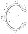
- FIG. 4 a second embodiment of the pneumatic radial tire according to the invention is shown in Fig. 4, wherein the same members as described in the first embodiment are the same numerals as those described in the first embodiment and the redundant description is omitted.
- the second embodiment has substantially the same structure as the first embodiment except that the pair of cross belt members 28A, 28B are arranged at an inner circumference side of the spiral belt 26 instead of being arranged at an outer circumference side of the spiral belt 26 in the first embodiment.
- the cords constituting the cross belt members 28A, 28B extend at an inclination angle opposite to each other with respect to the equatorial plane CL of the tire within the same range as in the first embodiment, and the initial tensile strength of the cord is also the same as in the first embodiment.
- the same mounting method as described in the first embodiment is adopted.
- the deformation and the resistance force of the tire are made optimum in correspondence to the difference of the external forces acting to the front and rear tires likewise the first embodiment.
- a third embodiment of the pneumatic radial tire according to the invention is shown in Fig. 5.
- the third embodiment has substantially the same structure as in the first embodiment except that an auxiliary belt 34 is further arranged between the carcass 12 and the spiral belt 26 as shown in Fig. 5.
- the cords constituting the auxiliary belt 34 are inclined at a given cord angle with respect to the equatorial plane CL.
- the spiral belt 26 is sandwiched between the pair of cross belt members 28A, 28B and the auxiliary belt 34.
- the tires 10 are mounted as the front and rear tires for the motorcycle in the same manner as in the first embodiment. In this case, the deformation and the resistance force of the tire are further improved owing to the presence of the auxiliary belt 34.
- a fourth embodiment of the pneumatic radial tire according to the invention is shown in Fig. 6.
- This embodiment is substantially the same structure as in the third embodiment except that the arrangement of the pair of cross belt members 28A, 28B and the auxiliary belt 34 is opposite to that of the third embodiment as shown in Fig. 6.
- the tires 10 are mounted as the front and rear tires for the motorcycle in the same manner as in the first embodiment. In this case, the deformation and the resistance force of the tire are further improved owing to the presence of the auxiliary belt 34 likewise the third embodiment.
- Example 1 uses the pneumatic radial tire 10 described in the first embodiment and Example 2 uses the pneumatic radial tire 10 described in the second embodiment.
- the conventional example uses a tire with a belt structure having no pair of cross belt members 28A, 28B and the comparative example uses a tire having a spiral belt 26 and a pair of cross belt members 28A, 28B except that the cord inclination in the pair of the cross belt members takes a herringbone form in a front tire and an inverted herringbone form in a rear tire.
- the actual running test is carried out to obtain results as shown in Table 1.
- Table 1 High-speed stability Shimmy Handling Corner gripping Quick response Neutral property Gripping limit Slipping controllability
- Conventional Example 100 100 100 100 100 100 100 100 100 100 100 100 100 100 100 100 100 100 100 100 100 100 100 100 100 Comparative Example 110 110 110 100 105 105 Example 1 130 120 130 120 120 120 Example 2 120 120 110 110 110 110 110 110 110 110 100 105 105 Example 1 130 120 130 120 120 120 120 Example 2 120 120
- the evaluation by the actual running test is an evaluation by a feeling of a test driver for the high-speed stability, shimmy, handling and corner gripping limit. From the results of Table 1, it can be understood that all evaluation points in Examples 1 and 2 are higher than those of Convention Example and Comparative Example.
- each evaluation point is represented by an index on the basis that the tire of Conventional Example 1 is 100, in which the larger the index value, the better the evaluation.
- the tires used in the actual running test have tire sizes of 120/70ZR17 as a front tire and 190/50ZR17 as a rear tire, respectively, while a rim used for the front tire has a size of MT3.50 ⁇ 17 and a rim used for the rear tire has a size of MT6.00 ⁇ 17.
- an air pressure is 250kPa in both the front and rear tires, and a motorcycle of YAMAHA R1 is used as a test vehicle.
- the material of the cord used in the spiral belt and the cross belt member according to the invention not only the steel but also the organic fiber can be adopted as mentioned above.
- the organic fiber there are mentioned aramid as an aromatic polyamide, PEN, PET, rayon, nylon as an aliphatic polyamide and the like, but the other resin materials may be used.
- an aramid cord or a steel cord can be used in the spiral belt.
- the method of mounting the pneumatic radial tire according to the invention has an excellent effect that the deformation and resistance force of the tire can be made optimum in correspondence to a difference between external forces respectively applied to the front and rear tires.
Landscapes
- Engineering & Computer Science (AREA)
- Mechanical Engineering (AREA)
- Tires In General (AREA)
Applications Claiming Priority (2)
| Application Number | Priority Date | Filing Date | Title |
|---|---|---|---|
| JP2000123587A JP2001301422A (ja) | 2000-04-25 | 2000-04-25 | 空気入りタイヤの装着構造 |
| JP2000123587 | 2000-04-25 |
Publications (3)
| Publication Number | Publication Date |
|---|---|
| EP1149714A2 true EP1149714A2 (de) | 2001-10-31 |
| EP1149714A3 EP1149714A3 (de) | 2002-07-17 |
| EP1149714B1 EP1149714B1 (de) | 2006-06-14 |
Family
ID=18633868
Family Applications (1)
| Application Number | Title | Priority Date | Filing Date |
|---|---|---|---|
| EP01303595A Expired - Lifetime EP1149714B1 (de) | 2000-04-25 | 2001-04-19 | Verfahren zur Montage eines radialen Fahrzeugreifens |
Country Status (5)
| Country | Link |
|---|---|
| US (1) | US6977020B2 (de) |
| EP (1) | EP1149714B1 (de) |
| JP (1) | JP2001301422A (de) |
| DE (1) | DE60120551T2 (de) |
| ES (1) | ES2266117T3 (de) |
Cited By (4)
| Publication number | Priority date | Publication date | Assignee | Title |
|---|---|---|---|---|
| EP1342592A3 (de) * | 2002-03-05 | 2003-11-19 | Sumitomo Rubber Industries Ltd. | Motorradreifen |
| EP1612058A1 (de) * | 2004-06-30 | 2006-01-04 | Sumitomo Rubber Industries Limited | Motorradreifen |
| EP2078622A1 (de) * | 2008-01-11 | 2009-07-15 | Continental Aktiengesellschaft | Fahrzeugluftreifen |
| CN103370187A (zh) * | 2011-02-17 | 2013-10-23 | 株式会社普利司通 | 用于修补子午线轮胎的补胎胶片、利用该补胎胶片修补子午线轮胎的方法以及利用该补胎胶片修补的子午线轮胎 |
Families Citing this family (14)
| Publication number | Priority date | Publication date | Assignee | Title |
|---|---|---|---|---|
| EP1547819A4 (de) * | 2002-08-09 | 2010-07-07 | Bridgestone Corp | Pneumatischer reifen für zweirädriges kraftfahrzeug |
| JP4558733B2 (ja) * | 2004-07-16 | 2010-10-06 | 株式会社ブリヂストン | 二輪自動車用タイヤ |
| JP4976001B2 (ja) * | 2005-11-02 | 2012-07-18 | 株式会社ブリヂストン | 二輪車用空気入りタイヤ |
| JP4889019B2 (ja) * | 2006-11-08 | 2012-02-29 | 株式会社ブリヂストン | 自動二輪車用空気入りタイヤ |
| KR100828688B1 (ko) | 2006-12-14 | 2008-05-09 | 기아자동차주식회사 | 차량용 래디얼 타이어의 스틸벨트 |
| WO2008114778A1 (ja) * | 2007-03-20 | 2008-09-25 | Bridgestone Corporation | 二輪車用タイヤ |
| JP4383465B2 (ja) * | 2007-06-07 | 2009-12-16 | 株式会社ブリヂストン | 自動二輪車用タイヤ対および自動二輪車用タイヤの使用方法 |
| US20090107609A1 (en) * | 2007-10-31 | 2009-04-30 | Walter Kevin Westgate | High Extensible Cut-Resistant Barrier |
| JP5350749B2 (ja) * | 2008-10-28 | 2013-11-27 | 住友ゴム工業株式会社 | 二輪自動車用タイヤ対 |
| JP5066220B2 (ja) * | 2010-05-17 | 2012-11-07 | 住友ゴム工業株式会社 | 空気入りタイヤ及びその製造方法 |
| FR2977828B1 (fr) * | 2011-07-13 | 2013-08-16 | Michelin Soc Tech | Pneumatique pliable, procede de pliage et utilisation |
| JP6130145B2 (ja) * | 2013-01-08 | 2017-05-17 | 株式会社ブリヂストン | 自動二輪車用空気入りタイヤ |
| JP6461651B2 (ja) * | 2015-03-09 | 2019-01-30 | 住友ゴム工業株式会社 | 二輪自動車用空気入りタイヤ |
| JP7835030B2 (ja) * | 2022-02-08 | 2026-03-25 | 住友ゴム工業株式会社 | 自動二輪車用タイヤ |
Family Cites Families (24)
| Publication number | Priority date | Publication date | Assignee | Title |
|---|---|---|---|---|
| DE2744997A1 (de) * | 1977-10-06 | 1979-04-19 | Continental Gummi Werke Ag | Fahrzeugluftreifen mit zwei oder mehreren nebeneinanderliegenden laufbaendern |
| JPS5973307A (ja) * | 1982-10-18 | 1984-04-25 | Bridgestone Corp | 二輪車用空気入りベルテツドタイヤ対 |
| FR2611599A1 (fr) * | 1987-02-23 | 1988-09-09 | Michelin & Cie | Paire de pneumatiques pour deux roues |
| JPH0655561B2 (ja) * | 1988-03-18 | 1994-07-27 | 株式会社ブリヂストン | 二輪車用タイヤ組立体 |
| JPH0325005A (ja) * | 1989-06-21 | 1991-02-01 | Bridgestone Corp | 二輪車用空気入りタイヤ対 |
| JPH0424102A (ja) * | 1990-05-16 | 1992-01-28 | Sumitomo Rubber Ind Ltd | 自動二輪車 |
| US5339878A (en) * | 1990-05-18 | 1994-08-23 | Bridgestone Corporation | Pneumatic tires for motorcycles including a spirally wound belt cord layer |
| ES2075426T3 (es) * | 1991-01-07 | 1995-10-01 | Michelin & Cie | Neumaticos para moto. |
| JP3035005B2 (ja) * | 1991-06-26 | 2000-04-17 | 株式会社ブリヂストン | 空気入りラジアルタイヤのタイヤ対 |
| JPH0664577A (ja) * | 1992-08-17 | 1994-03-08 | Sumitomo Rubber Ind Ltd | 自動二輪車 |
| JP2702873B2 (ja) * | 1992-09-16 | 1998-01-26 | 住友ゴム工業株式会社 | ラジアルタイヤ |
| JP3337505B2 (ja) * | 1992-11-20 | 2002-10-21 | 株式会社ブリヂストン | 空気入りタイヤ |
| JPH06344706A (ja) * | 1993-06-07 | 1994-12-20 | Yokohama Rubber Co Ltd:The | 乗用車用前後輪組み合わせタイヤ |
| JP2799322B2 (ja) * | 1993-06-07 | 1998-09-17 | 住友ゴム工業株式会社 | 自動二輪車用空気入りタイヤ |
| JP3537916B2 (ja) * | 1995-06-06 | 2004-06-14 | 株式会社ブリヂストン | 空気入りセミラジアルタイヤの組合せ体 |
| IT1277400B1 (it) * | 1995-08-01 | 1997-11-10 | Pirelli | Pneumatico ad elevata curvatura trasversale particolarmente per veicolo a due ruote |
| IT1283051B1 (it) * | 1996-05-22 | 1998-04-07 | Pirelli | Coppia di pneumatici ad elevata curvatura trasversale,particolarmente per veicoli a due ruote e metodo per il controllo del comportamento |
| JP3513332B2 (ja) * | 1996-08-09 | 2004-03-31 | 住友ゴム工業株式会社 | 自動二輪車用ラジアルタイヤ |
| FR2756778B1 (fr) * | 1996-12-06 | 1999-01-08 | Michelin & Cie | Armature de sommet pour pneumatique "poids-lourds" de rapport de forme inferieur ou egal a 0,65 |
| JP3648009B2 (ja) * | 1997-01-24 | 2005-05-18 | 株式会社ブリヂストン | 空気入りタイヤの装着方法 |
| US6397911B1 (en) * | 1997-12-29 | 2002-06-04 | Pirelli Pneumatici S.P.A. | High transverse-curvature motor-bike tire |
| JPH11291711A (ja) * | 1998-04-13 | 1999-10-26 | Sumitomo Rubber Ind Ltd | 自動二輪車用タイヤ |
| US6244315B1 (en) * | 1998-04-16 | 2001-06-12 | Pirelli Pneumatici S.P.A. | Tyre with high transverse curvature coefficient in particular for a two-wheeled vehicle |
| JP4187833B2 (ja) * | 1998-07-27 | 2008-11-26 | 株式会社ブリヂストン | 二輪自動車用空気入りタイヤ |
-
2000
- 2000-04-25 JP JP2000123587A patent/JP2001301422A/ja active Pending
-
2001
- 2001-04-19 DE DE60120551T patent/DE60120551T2/de not_active Expired - Lifetime
- 2001-04-19 EP EP01303595A patent/EP1149714B1/de not_active Expired - Lifetime
- 2001-04-19 ES ES01303595T patent/ES2266117T3/es not_active Expired - Lifetime
- 2001-04-25 US US09/840,824 patent/US6977020B2/en not_active Expired - Lifetime
Cited By (6)
| Publication number | Priority date | Publication date | Assignee | Title |
|---|---|---|---|---|
| EP1342592A3 (de) * | 2002-03-05 | 2003-11-19 | Sumitomo Rubber Industries Ltd. | Motorradreifen |
| US7204285B2 (en) | 2002-03-05 | 2007-04-17 | Sumitomo Rubber Industries, Ltd. | Motorcycle tire |
| EP1612058A1 (de) * | 2004-06-30 | 2006-01-04 | Sumitomo Rubber Industries Limited | Motorradreifen |
| US7343948B2 (en) | 2004-06-30 | 2008-03-18 | Sumitomo Rubber Industries, Ltd. | Pneumatic tire for two-wheeled motor vehicles |
| EP2078622A1 (de) * | 2008-01-11 | 2009-07-15 | Continental Aktiengesellschaft | Fahrzeugluftreifen |
| CN103370187A (zh) * | 2011-02-17 | 2013-10-23 | 株式会社普利司通 | 用于修补子午线轮胎的补胎胶片、利用该补胎胶片修补子午线轮胎的方法以及利用该补胎胶片修补的子午线轮胎 |
Also Published As
| Publication number | Publication date |
|---|---|
| US20010045263A1 (en) | 2001-11-29 |
| EP1149714B1 (de) | 2006-06-14 |
| EP1149714A3 (de) | 2002-07-17 |
| DE60120551T2 (de) | 2007-06-06 |
| JP2001301422A (ja) | 2001-10-31 |
| ES2266117T3 (es) | 2007-03-01 |
| DE60120551D1 (de) | 2006-07-27 |
| US6977020B2 (en) | 2005-12-20 |
Similar Documents
| Publication | Publication Date | Title |
|---|---|---|
| US6977020B2 (en) | Method of mounting a pneumatic radial tire | |
| JP4649215B2 (ja) | 自動二輪車用空気入りタイヤ | |
| EP1859961A2 (de) | Luftreifen für ein Motorrad | |
| JP4677116B2 (ja) | 二輪車用ラジアルタイヤ | |
| EP0568870B2 (de) | Reifen mit drei Gürtellagen | |
| JP4535460B2 (ja) | 自動二輪車用空気入りラジアルタイヤ | |
| EP1048491B1 (de) | Luftreifen und Verfahren zur Montage des Reifens | |
| JP4181262B2 (ja) | 二輪車用空気入りタイヤ | |
| JP4800392B2 (ja) | 改良されたベルト構造を有する空気タイヤ | |
| JP5089259B2 (ja) | 自動二輪車用空気入りタイヤ | |
| JP4553678B2 (ja) | 自動二輪車用空気入りタイヤ | |
| JP4540587B2 (ja) | 二輪車用空気入りタイヤ | |
| JP2009126394A (ja) | 自動二輪車用空気入りタイヤ | |
| JP2007084025A (ja) | 二輪車用空気入りタイヤ | |
| JP2006298082A (ja) | 二輪車用空気入りタイヤ | |
| JPH0234403A (ja) | 2輪車用空気入りラジアルタイヤ | |
| JP5541614B2 (ja) | 空気入りタイヤ | |
| JP4675710B2 (ja) | 自動二輪車用タイヤ | |
| KR102320105B1 (ko) | 핸들링이 강화된 공기입 타이어 | |
| JP4226355B2 (ja) | 自動二輪車用タイヤ対構造 | |
| JP4758248B2 (ja) | 自動二輪車用タイヤ | |
| JP4965167B2 (ja) | 自動二輪車用空気入りタイヤ | |
| JP2010143509A (ja) | 二輪自動車用タイヤ対 | |
| JPH038961B2 (de) | ||
| JP4573534B2 (ja) | 二輪車用空気入りタイヤ |
Legal Events
| Date | Code | Title | Description |
|---|---|---|---|
| PUAI | Public reference made under article 153(3) epc to a published international application that has entered the european phase |
Free format text: ORIGINAL CODE: 0009012 |
|
| AK | Designated contracting states |
Kind code of ref document: A2 Designated state(s): AT BE CH CY DE DK ES FI FR GB GR IE IT LI LU MC NL PT SE TR |
|
| AX | Request for extension of the european patent |
Free format text: AL;LT;LV;MK;RO;SI |
|
| PUAL | Search report despatched |
Free format text: ORIGINAL CODE: 0009013 |
|
| AK | Designated contracting states |
Kind code of ref document: A3 Designated state(s): AT BE CH CY DE DK ES FI FR GB GR IE IT LI LU MC NL PT SE TR |
|
| AX | Request for extension of the european patent |
Free format text: AL;LT;LV;MK;RO;SI |
|
| 17P | Request for examination filed |
Effective date: 20021219 |
|
| AKX | Designation fees paid |
Designated state(s): DE ES FR GB IT |
|
| 17Q | First examination report despatched |
Effective date: 20030801 |
|
| GRAP | Despatch of communication of intention to grant a patent |
Free format text: ORIGINAL CODE: EPIDOSNIGR1 |
|
| GRAS | Grant fee paid |
Free format text: ORIGINAL CODE: EPIDOSNIGR3 |
|
| GRAA | (expected) grant |
Free format text: ORIGINAL CODE: 0009210 |
|
| RIC1 | Information provided on ipc code assigned before grant |
Ipc: B60C 19/00 20060101AFI20060425BHEP Ipc: B60C 9/22 20060101ALI20060425BHEP Ipc: B60C 9/20 20060101ALI20060425BHEP |
|
| AK | Designated contracting states |
Kind code of ref document: B1 Designated state(s): DE ES FR GB IT |
|
| PG25 | Lapsed in a contracting state [announced via postgrant information from national office to epo] |
Ref country code: IT Free format text: LAPSE BECAUSE OF FAILURE TO SUBMIT A TRANSLATION OF THE DESCRIPTION OR TO PAY THE FEE WITHIN THE PRESCRIBED TIME-LIMIT;WARNING: LAPSES OF ITALIAN PATENTS WITH EFFECTIVE DATE BEFORE 2007 MAY HAVE OCCURRED AT ANY TIME BEFORE 2007. THE CORRECT EFFECTIVE DATE MAY BE DIFFERENT FROM THE ONE RECORDED. Effective date: 20060614 |
|
| REG | Reference to a national code |
Ref country code: GB Ref legal event code: FG4D |
|
| REF | Corresponds to: |
Ref document number: 60120551 Country of ref document: DE Date of ref document: 20060727 Kind code of ref document: P |
|
| ET | Fr: translation filed | ||
| REG | Reference to a national code |
Ref country code: ES Ref legal event code: FG2A Ref document number: 2266117 Country of ref document: ES Kind code of ref document: T3 |
|
| PLBE | No opposition filed within time limit |
Free format text: ORIGINAL CODE: 0009261 |
|
| STAA | Information on the status of an ep patent application or granted ep patent |
Free format text: STATUS: NO OPPOSITION FILED WITHIN TIME LIMIT |
|
| 26N | No opposition filed |
Effective date: 20070315 |
|
| PGFP | Annual fee paid to national office [announced via postgrant information from national office to epo] |
Ref country code: ES Payment date: 20120424 Year of fee payment: 12 |
|
| REG | Reference to a national code |
Ref country code: ES Ref legal event code: FD2A Effective date: 20140606 |
|
| PG25 | Lapsed in a contracting state [announced via postgrant information from national office to epo] |
Ref country code: ES Free format text: LAPSE BECAUSE OF NON-PAYMENT OF DUE FEES Effective date: 20130420 |
|
| REG | Reference to a national code |
Ref country code: FR Ref legal event code: CA Effective date: 20140812 |
|
| REG | Reference to a national code |
Ref country code: DE Ref legal event code: R081 Ref document number: 60120551 Country of ref document: DE Owner name: BRIDGESTONE CORPORATION, JP Free format text: FORMER OWNER: BRIDGESTONE CORP., TOKIO/TOKYO, JP Effective date: 20140828 |
|
| PGFP | Annual fee paid to national office [announced via postgrant information from national office to epo] |
Ref country code: GB Payment date: 20150420 Year of fee payment: 15 |
|
| PGFP | Annual fee paid to national office [announced via postgrant information from national office to epo] |
Ref country code: IT Payment date: 20150430 Year of fee payment: 15 |
|
| REG | Reference to a national code |
Ref country code: FR Ref legal event code: PLFP Year of fee payment: 16 |
|
| PGFP | Annual fee paid to national office [announced via postgrant information from national office to epo] |
Ref country code: DE Payment date: 20160421 Year of fee payment: 16 |
|
| PGFP | Annual fee paid to national office [announced via postgrant information from national office to epo] |
Ref country code: FR Payment date: 20160421 Year of fee payment: 16 |
|
| GBPC | Gb: european patent ceased through non-payment of renewal fee |
Effective date: 20160419 |
|
| PG25 | Lapsed in a contracting state [announced via postgrant information from national office to epo] |
Ref country code: GB Free format text: LAPSE BECAUSE OF NON-PAYMENT OF DUE FEES Effective date: 20160419 |
|
| PG25 | Lapsed in a contracting state [announced via postgrant information from national office to epo] |
Ref country code: IT Free format text: LAPSE BECAUSE OF NON-PAYMENT OF DUE FEES Effective date: 20160419 |
|
| REG | Reference to a national code |
Ref country code: DE Ref legal event code: R119 Ref document number: 60120551 Country of ref document: DE |
|
| REG | Reference to a national code |
Ref country code: FR Ref legal event code: ST Effective date: 20171229 |
|
| PG25 | Lapsed in a contracting state [announced via postgrant information from national office to epo] |
Ref country code: FR Free format text: LAPSE BECAUSE OF NON-PAYMENT OF DUE FEES Effective date: 20170502 Ref country code: DE Free format text: LAPSE BECAUSE OF NON-PAYMENT OF DUE FEES Effective date: 20171103 |