EP1152244A2 - Dispositif de positionnement d'objets - Google Patents
Dispositif de positionnement d'objets Download PDFInfo
- Publication number
- EP1152244A2 EP1152244A2 EP01108285A EP01108285A EP1152244A2 EP 1152244 A2 EP1152244 A2 EP 1152244A2 EP 01108285 A EP01108285 A EP 01108285A EP 01108285 A EP01108285 A EP 01108285A EP 1152244 A2 EP1152244 A2 EP 1152244A2
- Authority
- EP
- European Patent Office
- Prior art keywords
- insert
- sample
- optical sensor
- barcode
- sample tube
- Prior art date
- Legal status (The legal status is an assumption and is not a legal conclusion. Google has not performed a legal analysis and makes no representation as to the accuracy of the status listed.)
- Granted
Links
Images
Classifications
-
- G—PHYSICS
- G01—MEASURING; TESTING
- G01N—INVESTIGATING OR ANALYSING MATERIALS BY DETERMINING THEIR CHEMICAL OR PHYSICAL PROPERTIES
- G01N35/00—Automatic analysis not limited to methods or materials provided for in any single one of groups G01N1/00 - G01N33/00; Handling materials therefor
- G01N35/02—Automatic analysis not limited to methods or materials provided for in any single one of groups G01N1/00 - G01N33/00; Handling materials therefor using a plurality of sample containers moved by a conveyor system past one or more treatment or analysis stations
- G01N35/04—Details of the conveyor system
-
- G—PHYSICS
- G01—MEASURING; TESTING
- G01N—INVESTIGATING OR ANALYSING MATERIALS BY DETERMINING THEIR CHEMICAL OR PHYSICAL PROPERTIES
- G01N35/00—Automatic analysis not limited to methods or materials provided for in any single one of groups G01N1/00 - G01N33/00; Handling materials therefor
- G01N35/00584—Control arrangements for automatic analysers
- G01N35/00722—Communications; Identification
- G01N35/00732—Identification of carriers, materials or components in automatic analysers
- G01N2035/00742—Type of codes
- G01N2035/00752—Type of codes bar codes
-
- G—PHYSICS
- G01—MEASURING; TESTING
- G01N—INVESTIGATING OR ANALYSING MATERIALS BY DETERMINING THEIR CHEMICAL OR PHYSICAL PROPERTIES
- G01N35/00—Automatic analysis not limited to methods or materials provided for in any single one of groups G01N1/00 - G01N33/00; Handling materials therefor
- G01N35/02—Automatic analysis not limited to methods or materials provided for in any single one of groups G01N1/00 - G01N33/00; Handling materials therefor using a plurality of sample containers moved by a conveyor system past one or more treatment or analysis stations
- G01N35/04—Details of the conveyor system
- G01N2035/0474—Details of actuating means for conveyors or pipettes
- G01N2035/0491—Position sensing, encoding; closed-loop control
Definitions
- the invention relates to a device for positioning objects in a target position.
- Devices of this type are generally used in systems with transport systems used for which objects in predetermined target positions for a machine or manual processing must be run in.
- a major problem here is that objects are not only in specified target positions must be positioned as precisely as possible. Rather, the objects must also be clearly identifiable in order to Avoid confusion of objects.
- blood analyzers by means of which analyzes of blood samples be performed.
- the blood samples are in individual sample tubes included, which are fed to the blood analyzer one after the other.
- a needle which is placed over the closure of a sample tube a sample is taken in the interior, which is then subjected to an analysis.
- Such blood analyzers have a high throughput, so this a large amount of sample tubes are supplied per unit time.
- Carrying out the analyzes is an essential requirement that the individual Sample tubes are clearly identifiable and the analyzes the can be assigned to the respective sample tube. A mix up individual samples could be taken for the patient from whom the blood samples were taken have been misdiagnosed, which ultimately also poses a risk of the patient.
- sample tubes are typically used identified with unique identifiers by the operating personnel performing the blood analysis can be identified. So that can confusion of individual sample tubes can be excluded, however must carry out the blood tests and especially the transport the operator monitors the sample tube to the blood analyzer become. Aside from the fact that human error continues an incorrect assignment of performed analyzes to the associated ones Samples in sample tubes are possible, is a high one with such systems Personnel deployment required.
- the invention has for its object to provide a device which ensures an exact, automated positioning of objects, at the same time a clear identification and tracking of the objects is guaranteed.
- the device according to the invention for positioning objects in a Target position has an optical sensor with a light beam emitting Transmitter, a receiver and receiving light beams an evaluation unit.
- the target position is determined by means of the transmitted light beams scanned.
- the device has at least one receiving device, in which a predetermined number of objects in predetermined insertion positions is stored. Each insertion position is marked by a position mark characterized.
- the device also has a transport system, by means of which the receiving device moves relative to the optical sensor becomes. The cradle is stopped once the position mark an insertion position for a given object from the optical sensor is recorded, the respective object using object marks by means of of the sensor is identifiable.
- the main advantage of the device according to the invention is that by means of the optical sensor not only a precise positioning of the objects is made possible in a target position.
- by means of the optical Sensor ensures a clear identification of the objects, whereby at the same time a clear assignment of the objects to the insertion positions is guaranteed in the receiving device.
- the device Part of a blood analysis device.
- the blood analyzer has a blood analyzer.
- One component of the blood analyzer is one Sampling device with a needle.
- the objects are from sample tubes formed, which contain blood samples and closed with a closure are.
- the Insert the needle into the interior of the respective sample tube via the cap.
- the sample tubes are automatically supplied to the needle, the sample tubes in sample holders forming receptacles individually supplied to the sampling device in succession become.
- the sample tubes are stored in slots in the sample holder.
- a position mark is arranged on each of these inserts, which consists of a position barcode and two reference line elements.
- Position barcode is the number of the slot and thus its location within of the transport system.
- On each of the sample tubes is also arranged an object mark designed as an object barcode.
- the reference line elements form a target, which is used for positioning an insert into the desired position in which the needle is arranged.
- the scanning range is expediently the optical sensor so that only the position marks on the inserts, however, the object marks are not recorded.
- the needle located there becomes the sampling device is inserted into the corresponding sample tube, after which a sample from the sample tube for performing an analysis is removed.
- the analysis results are together with the Information of the assigned position barcode and object barcode is saved, so that the analysis result can be clearly assigned.
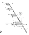
- Figure 1 shows schematically an embodiment of the invention Device for positioning objects in a target position.
- the device is part of a blood analysis device 1.
- the objects are formed by sample tubes 2, which are preferably Contain blood samples and a top in each with a closure 3 in Form of a plug are closed.
- the sample tubes 2 are in several Sample holders 4 are stored, which receiving devices for the objects form.
- the sample holders 4 are each of identical design and each have a predetermined number of inserts 5.
- the inserts 5 are identically designed and each serve to hold a sample tube 2nd
- the sample holders 4 are moved in a conveying direction by means of a transport system 6 v moved and fed to a blood analyzer 7.
- the blood analyzer 7 forms the core of the blood analysis device 1 and is used for implementation of analyzes of blood samples.
- the transport system 6 is formed by a conveyor system in which the Sample holders 4 are arranged one behind the other at predetermined intervals.
- the Sample tubes 2 stand vertically in the respective sample holder 4.
- the sample holders 4 transported on the conveyor system become one after the other a sampling device cooperating with the blood analyzer 7 8 fed.
- the sampling device 8 preferably forms a part of the blood analyzer 7.
- the sampling device 8 has an automatically controlled needle 9 for taking samples from the sample tube 2.
- To remove one Sample is the corresponding sample tube 2 in a target position directly positioned below the needle 9.
- the target position is vertical extending straight line S formed transversely to the conveying direction v of the conveyor system runs.
- the longitudinal axis of the needle 9 runs along this straight line S.
- the device for positioning the sample tube 2 in the desired position essentially comprises an optical sensor 10 and one not shown Control unit for controlling the optical sensor 10 and the sampling device 8th.
- the optical sensor 10 is designed as a barcode reader. This points in Essentially a transmitter 11 emitting light rays, a received light rays receiving receiver, a deflection unit and a Evaluation unit on.
- the transmitted light beams 11 routed via the deflection unit periodically scan a scanning area with the barcode reader within the scanning area horizontal, contrasting marks recorded. Doing so the transmitted light rays reflected at the marks as received light rays 11 an amplitude modulation corresponding to the contrast pattern of the mark imprinted, which evaluates to capture the brand in the evaluation unit becomes.
- the scanning area captured by the transmitted light beams 11 runs along the line Straight line forming the nominal position S.
- the transmitted light beams can be used 11 of the bar code reader, a line-shaped scanning area can be detected.
- a flat grid is created by means of the transmitted light beams 11 scanned to be arranged on the sample holder 4 and / or on the sample tube 2 To capture brands.
- the grid forms a rectangular surface element, the size of this surface element in the plane of the sampled Sample holder 4 is adapted to the sizes of the marks to be detected.
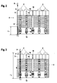
- FIGS. 2-5 each show the one facing the optical sensor 10 and side surface of a sample holder 4 scanned by the transmitted light beams 11 shown.
- the sample holder 4 has an essentially cuboidal contour, wherein the side surface facing the optical sensor 10 is essentially one forms a flat, rectangular surface.
- the one shown in Figures 2-5 Sample holder 4 has five identical ones running in the vertical direction Inserts 5 on. The inserts 5 are arranged equidistantly and open the top of the sample holder 4.
- the stored in the slots 5, in Essentially cylindrical sample tubes 2 stand with their closures over the upper edges of the slots 5.
- Each position mark has a position barcode 12.
- barcode 12 is the number of the respective insert 5 of the sample holder 4 coded.
- the inserts 5 of all the sample holders 4 are continuous Numbered.
- the position is therefore by the respective number of each insert 5 within the entirety of all sample holders 4 of the Transport system 6 clearly identified. It is expedient that Number of a slot 5 not only in the respective position barcode 12 am Insert 5 attached, but also in plain text in the form of a sequence of digits.
- the position bar codes 12 consist of a sequence of light and dark Line elements, the longitudinal axes of which are transverse to the longitudinal axis of the respective insert 5 and across the scanning direction of the transmitted light beams 11 of the optical Sensor 10 run.
- Each position barcode 12 has a quiet zone at its longitudinal ends predetermined width. There is a reference line element in each of these quiet zones 13. The longitudinal axes of the reference line elements 13 run parallel to the longitudinal axes of the line elements of the respective position barcode 12th
- the reference line elements 13 forming a target are part of it a position mark and serve to position the respective insert 5 in the target position.
- Object barcode 14 On the outside of the sample tube 2 there is an object mark Object barcode 14 applied, in which the content of a sample tube 2 is encoded.
- Each insert 5 has an opening 15, which on the optical sensor 10 facing side surface of the sample holder 4 opens out.
- the opening 15 is matched to the size of an object barcode 14, so that it passes through the opening 15 is completely visible and detected by the optical sensor 10 if the sample tube 2 is in the slot 5.
- the runs Longitudinal axis of opening 15 in the longitudinal direction of insert 5.
- Insert 5 a reference barcode 16 for checking the occupancy of the insert 5 provided with a sample tube 2.
- the reference barcode is 16 visible when the insert 5 is empty through the opening 15 and can thus be removed from the optical sensor 10 are scanned. However, if a sample tube 2 is in the Stored in the egg slot, the sample tube 2 covers the reference barcode 16, see above that this cannot be scanned by the optical sensor 10.
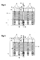
- the position marks, the object marks and the reference marks become scanned by the optical sensor 10, the scanning range of the sensor 10 is formed by a flat grid, the longitudinal axis along which the Straight line S formed, along which the needle 9 of the Sampling device 8 runs.
- the width of the grid is constant and is designated ⁇ d in FIGS. 2-5.
- the optical sensor 10 can be switched between two operating modes. In A first operating mode is used to position an insert 5 in the Target position of the transmitted light beams 11 of the optical sensor 10 is a grid the width ⁇ d and the length ⁇ x.
- the length of the grid is such the size of the position marks that the optical sensor 10 adapted Position marks are completely recorded, the object marks and the reference barcodes 16, however, are outside the grid.
- a grid of the width ⁇ d and the length ⁇ y sampled In a second operating mode, one is in the target position Insert 5 from the optical sensor 10 a grid of the width ⁇ d and the length ⁇ y sampled.
- the length ⁇ y of the grid extends over the entire Height of the sample holder 4, so that both the position marks in the second operating mode as well as the object marks and the reference barcodes 16 become.
- the switch from the first to the second operating mode is carried out by a Trigger signal, which is generated internally in the evaluation unit, as soon as a Insert 5 is detected lying in the desired position by the optical sensor 10.
- the switch from the second to the first operating mode is carried out by a external trigger signal, which is preferably generated in the control unit is and is read into the optical sensor 10.
- the sample holder 4 along the conveying direction v moved relative to the optical sensor 10. None of the slots are there 5 in the target position.
- the optical sensor 10 is in the first Operating mode, so that a grid of length ⁇ x for detecting the position marks is scanned.
- the positioning in the target position is then complete when the grid completely on the reference line elements 13 forming the target Position mark lies.
- the lengths of the identically designed reference line elements 13 are included slightly larger than the width ⁇ d of the grid and smaller than the diameter of the Closures trained. If a position mark is found while scanning, it is ensured that the entire grid lies on the reference lines, that the respective insert 5 with sufficient accuracy in the target position lies, so that in any case the needle 9 of the sampling device 8 lies above the closure 3 and is inserted into it. In particular is due to the dimensioning of the grid and the reference line elements 13 ensures that an insert 5 opposite the target position forming straight line S is not tilted, which means inserting the needle 9 would hinder in the closure 3.
- the trigger signal is generated in the control unit generated to switch to the first operating mode.
- the conveyor system is set in motion again via the control unit. After that the sample holder 4 is further conveyed until the next insert 5 in the target position is positioned. This way, all bays are 5 the sample holder 4 is positioned one after the other in the desired position.
- Figure 4 shows the positioning of an empty slot 5 in the target position. The positioning is not yet complete, since the grid of the optical Sensor 10 is not yet completely on the reference line elements 13 this slot 5 is.
- Figure 5 shows this insert 5 in the target position, with the switchover in the second operating mode after detection of the position barcode 12 has taken place on this insert 5. Since this insert 5 is empty, is not an object barcode 14 of a sample tube 2, but the reference barcode 16 detected at this slot 5. This is in the evaluation unit of the sensor 10 found that the insert 5 is empty. Preferably then a warning or error message is generated in the evaluation unit, which shows the operator that the slot 5 is not occupied. Because of The warning or error message is also sent to the sampling device via the control unit 8 deactivated. As a result, the needle 9 remains in its rest position, to avoid damage or malfunction.
Landscapes
- Physics & Mathematics (AREA)
- Health & Medical Sciences (AREA)
- Life Sciences & Earth Sciences (AREA)
- Chemical & Material Sciences (AREA)
- Analytical Chemistry (AREA)
- Biochemistry (AREA)
- General Health & Medical Sciences (AREA)
- General Physics & Mathematics (AREA)
- Immunology (AREA)
- Pathology (AREA)
- Automatic Analysis And Handling Materials Therefor (AREA)
- Length Measuring Devices By Optical Means (AREA)
Applications Claiming Priority (2)
| Application Number | Priority Date | Filing Date | Title |
|---|---|---|---|
| DE10017718 | 2000-04-11 | ||
| DE10017718 | 2000-04-11 |
Publications (3)
| Publication Number | Publication Date |
|---|---|
| EP1152244A2 true EP1152244A2 (fr) | 2001-11-07 |
| EP1152244A3 EP1152244A3 (fr) | 2004-01-14 |
| EP1152244B1 EP1152244B1 (fr) | 2006-08-16 |
Family
ID=7638191
Family Applications (1)
| Application Number | Title | Priority Date | Filing Date |
|---|---|---|---|
| EP01108285A Expired - Lifetime EP1152244B1 (fr) | 2000-04-11 | 2001-04-02 | Dispositif de positionnement d'objets |
Country Status (3)
| Country | Link |
|---|---|
| US (1) | US6465770B2 (fr) |
| EP (1) | EP1152244B1 (fr) |
| DE (1) | DE50110732D1 (fr) |
Cited By (1)
| Publication number | Priority date | Publication date | Assignee | Title |
|---|---|---|---|---|
| EP3365687B1 (fr) | 2015-10-23 | 2024-07-10 | Gen-Probe Incorporated | Systèmes et procédés de lecture de marquages lisibles par machine sur des rayonnages et réceptacles |
Families Citing this family (15)
| Publication number | Priority date | Publication date | Assignee | Title |
|---|---|---|---|---|
| US6870503B2 (en) | 2002-11-19 | 2005-03-22 | Farrokh Mohamadi | Beam-forming antenna system |
| WO2005098455A1 (fr) * | 2004-04-07 | 2005-10-20 | Tecan Trading Ag | Dispositif et procede d'identification, de localisation et de poursuite d'objets situes sur des equipements de laboratoire |
| US7278328B2 (en) * | 2004-09-03 | 2007-10-09 | Protedyne Corporation | Method and apparatus for handling sample holders |
| EP2610622A1 (fr) | 2007-12-31 | 2013-07-03 | Oridion Medical 1987 Ltd. | Vérificateur de tube |
| USD811616S1 (en) | 2015-12-18 | 2018-02-27 | Abbott Laboratories | Tube rack |
| USD793473S1 (en) | 2015-12-18 | 2017-08-01 | Abbott Laboratories | Print tape cartridge |
| USD802787S1 (en) | 2015-12-18 | 2017-11-14 | Abbott Laboratories | Slide carrier |
| USD782695S1 (en) | 2015-12-18 | 2017-03-28 | Abbott Laboratories | Slide carrier |
| USD812244S1 (en) | 2015-12-18 | 2018-03-06 | Abbott Laboratories | Tube rack |
| USD799055S1 (en) | 2015-12-18 | 2017-10-03 | Abbott Laboratories | Smear tape cartridge |
| USD799057S1 (en) | 2015-12-18 | 2017-10-03 | Abbott Laboratories | Slide rack |
| USD782064S1 (en) | 2015-12-18 | 2017-03-21 | Abbott Laboratories | Tube rack |
| USD799058S1 (en) | 2016-02-18 | 2017-10-03 | Abbott Laboratories | Slide caddy |
| US10598637B2 (en) * | 2017-07-18 | 2020-03-24 | Perkinelmer Health Sciences, Inc. | Automated thermal desorption systems configured to determine sample tube orientation and/or cap presence, and related methods |
| US10816516B2 (en) | 2018-03-28 | 2020-10-27 | Perkinelmer Health Sciences, Inc. | Autosamplers and gas chromatographic systems and methods including same |
Family Cites Families (5)
| Publication number | Priority date | Publication date | Assignee | Title |
|---|---|---|---|---|
| US3897216A (en) * | 1971-11-03 | 1975-07-29 | Coulter Chemistry Inc | Sample cup holder |
| JPS61137066A (ja) * | 1984-12-07 | 1986-06-24 | Toshiba Corp | 自動化学分析装置の測光方式 |
| DE8816086U1 (de) * | 1988-12-24 | 1989-02-09 | Laboratorium Prof. Dr. Rudolf Berthold, 7547 Wildbad | Vorrichtung zur Positionierung eines Sternrades |
| JP3193443B2 (ja) * | 1992-04-24 | 2001-07-30 | オリンパス光学工業株式会社 | 自動分析装置 |
| US5439645A (en) * | 1993-01-25 | 1995-08-08 | Coulter Corporation | Apparatus for automatically, selectively handling multiple, randomly associated hematological samples |
-
2001
- 2001-04-02 EP EP01108285A patent/EP1152244B1/fr not_active Expired - Lifetime
- 2001-04-02 DE DE50110732T patent/DE50110732D1/de not_active Expired - Fee Related
- 2001-04-04 US US09/824,535 patent/US6465770B2/en not_active Expired - Fee Related
Cited By (1)
| Publication number | Priority date | Publication date | Assignee | Title |
|---|---|---|---|---|
| EP3365687B1 (fr) | 2015-10-23 | 2024-07-10 | Gen-Probe Incorporated | Systèmes et procédés de lecture de marquages lisibles par machine sur des rayonnages et réceptacles |
Also Published As
| Publication number | Publication date |
|---|---|
| EP1152244B1 (fr) | 2006-08-16 |
| US6465770B2 (en) | 2002-10-15 |
| US20020017602A1 (en) | 2002-02-14 |
| DE50110732D1 (de) | 2006-09-28 |
| EP1152244A3 (fr) | 2004-01-14 |
Similar Documents
| Publication | Publication Date | Title |
|---|---|---|
| EP0738986B1 (fr) | Analyseur avec lecteur de code à barres fixe | |
| EP1152244A2 (fr) | Dispositif de positionnement d'objets | |
| DE69308957T2 (de) | Verfahren und Vorrichtung zur Handhabung von Proben | |
| EP0738541B1 (fr) | Support pour récipients | |
| DE2755264C3 (de) | Anlage zur chemischen Analyse | |
| DE3490478T1 (de) | Kassette zum Tragen von Probenbehältern unterschiedlichen Durchmessers und/oder Länge | |
| EP0555739A1 (fr) | Dispositif automatique de pipettage | |
| DE3611536A1 (de) | Vorrichtung zur automatischen ueberpruefung von transparenten objekten, insbesondere von glasflaschen | |
| EP1223415A2 (fr) | Dispositif pour calibrer des multicanaux pipettes à l'aide d'un appareil pour le transport de récipients vers un dispositif de mesure | |
| EP3436832B1 (fr) | Dispositif de transport | |
| EP3035303B1 (fr) | Automate de reprise | |
| DE102017006566B3 (de) | Vorrichtung und Verfahren zur optischen Überwachung von Oberflächen eines Körpers | |
| WO2012146772A1 (fr) | Dispositif de poinçonnage pourvu d'une plaque de réception éclairée | |
| EP0230892A2 (fr) | Dispositif optique de balayage par une roue à miroir | |
| DE10260201A1 (de) | Verfahren und Vorrichtung zur Erfassung von auf einem Fördermittel bewegten Objekten mittels eines optoelektronischen Sensors | |
| DE1673107C3 (de) | Anordnung zur Aufbewahrung und Analyse einer Flüssigkeit | |
| WO1994017395A1 (fr) | Procede pour le controle de la surface de plusieurs petits objets et dispositif pour l'application de ce procede | |
| EP1972943A2 (fr) | Installation destinée à la réalisation d'analyses de sang | |
| EP2107534A1 (fr) | Automate de reprise pour bouteilles consignées | |
| DE102009036389A1 (de) | Verfahren und Vorrichtung zur Überprüfung von mit Gefäßen bestückten oder bestückbaren, oben offenen Aufnahmebehältern | |
| WO2021151434A1 (fr) | Support pour élément de protection contre les rayons x | |
| DE3038147C2 (fr) | ||
| EP0597353A2 (fr) | Méthode de contrôle de caisses de bouteilles et dispositif de mise en oeuvre de la méthode | |
| EP1010649B1 (fr) | Procédé de fonctionnement d'un dispositif de transport et dispositif de transport correspondant | |
| DE69416752T2 (de) | Vorrichtung zur Lagerung von zylindrischen Gegenständen, mit schneller Be- und Entladung |
Legal Events
| Date | Code | Title | Description |
|---|---|---|---|
| PUAI | Public reference made under article 153(3) epc to a published international application that has entered the european phase |
Free format text: ORIGINAL CODE: 0009012 |
|
| 17P | Request for examination filed |
Effective date: 20010423 |
|
| AK | Designated contracting states |
Kind code of ref document: A2 Designated state(s): AT BE CH CY DE DK ES FI FR GB GR IE IT LI LU MC NL PT SE TR |
|
| AX | Request for extension of the european patent |
Free format text: AL;LT;LV;MK;RO;SI |
|
| PUAL | Search report despatched |
Free format text: ORIGINAL CODE: 0009013 |
|
| AK | Designated contracting states |
Kind code of ref document: A3 Designated state(s): AT BE CH CY DE DK ES FI FR GB GR IE IT LI LU MC NL PT SE TR |
|
| AX | Request for extension of the european patent |
Extension state: AL LT LV MK RO SI |
|
| 17Q | First examination report despatched |
Effective date: 20040423 |
|
| AKX | Designation fees paid |
Designated state(s): CH DE FR GB IT LI NL |
|
| GRAP | Despatch of communication of intention to grant a patent |
Free format text: ORIGINAL CODE: EPIDOSNIGR1 |
|
| GRAS | Grant fee paid |
Free format text: ORIGINAL CODE: EPIDOSNIGR3 |
|
| GRAA | (expected) grant |
Free format text: ORIGINAL CODE: 0009210 |
|
| RAP1 | Party data changed (applicant data changed or rights of an application transferred) |
Owner name: LEUZE ELECTRONIC GMBH + CO. KG |
|
| AK | Designated contracting states |
Kind code of ref document: B1 Designated state(s): CH DE FR GB IT LI NL |
|
| PG25 | Lapsed in a contracting state [announced via postgrant information from national office to epo] |
Ref country code: IT Free format text: LAPSE BECAUSE OF FAILURE TO SUBMIT A TRANSLATION OF THE DESCRIPTION OR TO PAY THE FEE WITHIN THE PRESCRIBED TIME-LIMIT;WARNING: LAPSES OF ITALIAN PATENTS WITH EFFECTIVE DATE BEFORE 2007 MAY HAVE OCCURRED AT ANY TIME BEFORE 2007. THE CORRECT EFFECTIVE DATE MAY BE DIFFERENT FROM THE ONE RECORDED. Effective date: 20060816 |
|
| REG | Reference to a national code |
Ref country code: GB Ref legal event code: FG4D Free format text: NOT ENGLISH |
|
| GBT | Gb: translation of ep patent filed (gb section 77(6)(a)/1977) |
Effective date: 20060822 |
|
| REG | Reference to a national code |
Ref country code: CH Ref legal event code: NV Representative=s name: ROTTMANN, ZIMMERMANN + PARTNER AG Ref country code: CH Ref legal event code: EP |
|
| REF | Corresponds to: |
Ref document number: 50110732 Country of ref document: DE Date of ref document: 20060928 Kind code of ref document: P |
|
| ET | Fr: translation filed | ||
| PLBE | No opposition filed within time limit |
Free format text: ORIGINAL CODE: 0009261 |
|
| STAA | Information on the status of an ep patent application or granted ep patent |
Free format text: STATUS: NO OPPOSITION FILED WITHIN TIME LIMIT |
|
| 26N | No opposition filed |
Effective date: 20070518 |
|
| PGFP | Annual fee paid to national office [announced via postgrant information from national office to epo] |
Ref country code: DE Payment date: 20080506 Year of fee payment: 8 |
|
| PGFP | Annual fee paid to national office [announced via postgrant information from national office to epo] |
Ref country code: FR Payment date: 20090414 Year of fee payment: 9 Ref country code: IT Payment date: 20090423 Year of fee payment: 9 Ref country code: NL Payment date: 20090415 Year of fee payment: 9 |
|
| PGFP | Annual fee paid to national office [announced via postgrant information from national office to epo] |
Ref country code: CH Payment date: 20090417 Year of fee payment: 9 |
|
| PGFP | Annual fee paid to national office [announced via postgrant information from national office to epo] |
Ref country code: GB Payment date: 20090421 Year of fee payment: 9 |
|
| PG25 | Lapsed in a contracting state [announced via postgrant information from national office to epo] |
Ref country code: DE Free format text: LAPSE BECAUSE OF NON-PAYMENT OF DUE FEES Effective date: 20091103 |
|
| REG | Reference to a national code |
Ref country code: NL Ref legal event code: V1 Effective date: 20101101 |
|
| REG | Reference to a national code |
Ref country code: CH Ref legal event code: PL |
|
| GBPC | Gb: european patent ceased through non-payment of renewal fee |
Effective date: 20100402 |
|
| REG | Reference to a national code |
Ref country code: FR Ref legal event code: ST Effective date: 20101230 |
|
| PG25 | Lapsed in a contracting state [announced via postgrant information from national office to epo] |
Ref country code: NL Free format text: LAPSE BECAUSE OF NON-PAYMENT OF DUE FEES Effective date: 20101101 |
|
| PG25 | Lapsed in a contracting state [announced via postgrant information from national office to epo] |
Ref country code: LI Free format text: LAPSE BECAUSE OF NON-PAYMENT OF DUE FEES Effective date: 20100430 Ref country code: CH Free format text: LAPSE BECAUSE OF NON-PAYMENT OF DUE FEES Effective date: 20100430 |
|
| PG25 | Lapsed in a contracting state [announced via postgrant information from national office to epo] |
Ref country code: IT Free format text: LAPSE BECAUSE OF NON-PAYMENT OF DUE FEES Effective date: 20100402 Ref country code: GB Free format text: LAPSE BECAUSE OF NON-PAYMENT OF DUE FEES Effective date: 20100402 |
|
| PG25 | Lapsed in a contracting state [announced via postgrant information from national office to epo] |
Ref country code: FR Free format text: LAPSE BECAUSE OF NON-PAYMENT OF DUE FEES Effective date: 20100430 |