EP1152316A2 - Procédé et dispositif sans fil de supervision et contrôle de la température d'aliments - Google Patents
Procédé et dispositif sans fil de supervision et contrôle de la température d'aliments Download PDFInfo
- Publication number
- EP1152316A2 EP1152316A2 EP01304035A EP01304035A EP1152316A2 EP 1152316 A2 EP1152316 A2 EP 1152316A2 EP 01304035 A EP01304035 A EP 01304035A EP 01304035 A EP01304035 A EP 01304035A EP 1152316 A2 EP1152316 A2 EP 1152316A2
- Authority
- EP
- European Patent Office
- Prior art keywords
- temperature
- refrigeration
- case
- receiver
- controller
- Prior art date
- Legal status (The legal status is an assumption and is not a legal conclusion. Google has not performed a legal analysis and makes no representation as to the accuracy of the status listed.)
- Withdrawn
Links
Images


Classifications
-
- F—MECHANICAL ENGINEERING; LIGHTING; HEATING; WEAPONS; BLASTING
- F25—REFRIGERATION OR COOLING; COMBINED HEATING AND REFRIGERATION SYSTEMS; HEAT PUMP SYSTEMS; MANUFACTURE OR STORAGE OF ICE; LIQUEFACTION SOLIDIFICATION OF GASES
- F25D—REFRIGERATORS; COLD ROOMS; ICE-BOXES; COOLING OR FREEZING APPARATUS NOT OTHERWISE PROVIDED FOR
- F25D29/00—Arrangement or mounting of control or safety devices
-
- H—ELECTRICITY
- H04—ELECTRIC COMMUNICATION TECHNIQUE
- H04Q—SELECTING
- H04Q9/00—Arrangements in telecontrol or telemetry systems for selectively calling a substation from a main station, in which substation desired apparatus is selected for applying a control signal thereto or for obtaining measured values therefrom
-
- G—PHYSICS
- G05—CONTROLLING; REGULATING
- G05D—SYSTEMS FOR CONTROLLING OR REGULATING NON-ELECTRIC VARIABLES
- G05D23/00—Control of temperature
- G05D23/19—Control of temperature characterised by the use of electric means
-
- G—PHYSICS
- G05—CONTROLLING; REGULATING
- G05D—SYSTEMS FOR CONTROLLING OR REGULATING NON-ELECTRIC VARIABLES
- G05D23/00—Control of temperature
- G05D23/19—Control of temperature characterised by the use of electric means
- G05D23/1902—Control of temperature characterised by the use of electric means characterised by the use of a variable reference value
- G05D23/1905—Control of temperature characterised by the use of electric means characterised by the use of a variable reference value associated with tele control
-
- F—MECHANICAL ENGINEERING; LIGHTING; HEATING; WEAPONS; BLASTING
- F25—REFRIGERATION OR COOLING; COMBINED HEATING AND REFRIGERATION SYSTEMS; HEAT PUMP SYSTEMS; MANUFACTURE OR STORAGE OF ICE; LIQUEFACTION SOLIDIFICATION OF GASES
- F25B—REFRIGERATION MACHINES, PLANTS OR SYSTEMS; COMBINED HEATING AND REFRIGERATION SYSTEMS; HEAT PUMP SYSTEMS
- F25B2400/00—Component parts or details not otherwise provided for in this subclass
- F25B2400/07—Details of compressors or related parts
- F25B2400/075—Details of compressors or related parts with parallel compressors
-
- F—MECHANICAL ENGINEERING; LIGHTING; HEATING; WEAPONS; BLASTING
- F25—REFRIGERATION OR COOLING; COMBINED HEATING AND REFRIGERATION SYSTEMS; HEAT PUMP SYSTEMS; MANUFACTURE OR STORAGE OF ICE; LIQUEFACTION SOLIDIFICATION OF GASES
- F25B—REFRIGERATION MACHINES, PLANTS OR SYSTEMS; COMBINED HEATING AND REFRIGERATION SYSTEMS; HEAT PUMP SYSTEMS
- F25B2400/00—Component parts or details not otherwise provided for in this subclass
- F25B2400/22—Refrigeration systems for supermarkets
-
- F—MECHANICAL ENGINEERING; LIGHTING; HEATING; WEAPONS; BLASTING
- F25—REFRIGERATION OR COOLING; COMBINED HEATING AND REFRIGERATION SYSTEMS; HEAT PUMP SYSTEMS; MANUFACTURE OR STORAGE OF ICE; LIQUEFACTION SOLIDIFICATION OF GASES
- F25B—REFRIGERATION MACHINES, PLANTS OR SYSTEMS; COMBINED HEATING AND REFRIGERATION SYSTEMS; HEAT PUMP SYSTEMS
- F25B2600/00—Control issues
- F25B2600/07—Remote controls
-
- F—MECHANICAL ENGINEERING; LIGHTING; HEATING; WEAPONS; BLASTING
- F25—REFRIGERATION OR COOLING; COMBINED HEATING AND REFRIGERATION SYSTEMS; HEAT PUMP SYSTEMS; MANUFACTURE OR STORAGE OF ICE; LIQUEFACTION SOLIDIFICATION OF GASES
- F25D—REFRIGERATORS; COLD ROOMS; ICE-BOXES; COOLING OR FREEZING APPARATUS NOT OTHERWISE PROVIDED FOR
- F25D2500/00—Problems to be solved
- F25D2500/04—Calculation of parameters
-
- F—MECHANICAL ENGINEERING; LIGHTING; HEATING; WEAPONS; BLASTING
- F25—REFRIGERATION OR COOLING; COMBINED HEATING AND REFRIGERATION SYSTEMS; HEAT PUMP SYSTEMS; MANUFACTURE OR STORAGE OF ICE; LIQUEFACTION SOLIDIFICATION OF GASES
- F25D—REFRIGERATORS; COLD ROOMS; ICE-BOXES; COOLING OR FREEZING APPARATUS NOT OTHERWISE PROVIDED FOR
- F25D2700/00—Means for sensing or measuring; Sensors therefor
- F25D2700/10—Sensors measuring the temperature of the evaporator
-
- F—MECHANICAL ENGINEERING; LIGHTING; HEATING; WEAPONS; BLASTING
- F25—REFRIGERATION OR COOLING; COMBINED HEATING AND REFRIGERATION SYSTEMS; HEAT PUMP SYSTEMS; MANUFACTURE OR STORAGE OF ICE; LIQUEFACTION SOLIDIFICATION OF GASES
- F25D—REFRIGERATORS; COLD ROOMS; ICE-BOXES; COOLING OR FREEZING APPARATUS NOT OTHERWISE PROVIDED FOR
- F25D2700/00—Means for sensing or measuring; Sensors therefor
- F25D2700/12—Sensors measuring the inside temperature
- F25D2700/123—Sensors measuring the inside temperature more than one sensor measuring the inside temperature in a compartment
-
- F—MECHANICAL ENGINEERING; LIGHTING; HEATING; WEAPONS; BLASTING
- F25—REFRIGERATION OR COOLING; COMBINED HEATING AND REFRIGERATION SYSTEMS; HEAT PUMP SYSTEMS; MANUFACTURE OR STORAGE OF ICE; LIQUEFACTION SOLIDIFICATION OF GASES
- F25D—REFRIGERATORS; COLD ROOMS; ICE-BOXES; COOLING OR FREEZING APPARATUS NOT OTHERWISE PROVIDED FOR
- F25D2700/00—Means for sensing or measuring; Sensors therefor
- F25D2700/16—Sensors measuring the temperature of products
-
- G—PHYSICS
- G01—MEASURING; TESTING
- G01K—MEASURING TEMPERATURE; MEASURING QUANTITY OF HEAT; THERMALLY-SENSITIVE ELEMENTS NOT OTHERWISE PROVIDED FOR
- G01K7/00—Measuring temperature based on the use of electric or magnetic elements directly sensitive to heat ; Power supply therefor, e.g. using thermoelectric elements
- G01K7/42—Circuits effecting compensation of thermal inertia; Circuits for predicting the stationary value of a temperature
- G01K2007/422—Dummy objects used for estimating temperature of real objects
Definitions
- the present invention relates generally to monitoring and controlling temperature of food display cases and, more specifically, to a method and apparatus for monitoring and controlling food temperature.
- Produced food travels from processing plants to grocery stores, where the food product remains on display case shelves for extended periods of time.
- the food product should not exceed critical temperature limits while being displayed in the grocery store display cases.
- the product temperature should not exceed 41° F.
- the product temperature should not be less than 140° F. In other words, the critical temperature limits are approximately 41° and 140° F. Between these critical temperature limits, bacteria grow at a faster rate.
- a main controller typically logs or controls temperature.
- the main controller is installed in the compressor room, which is located on the roof or back of the grocery store.
- the conventional method for monitoring and controlling the display case temperature requires a discharge air temperature sensor mounted in the display case.
- the discharge air temperature sensor is typically connected to an analog input board, which is also typically located in the compressor room.
- a temperature wire must be pulled from the display case to the compressor room, which is typically difficult and increasingly expensive depending on how far away the compressor room is from the display case. Further, this wiring and installation process is more expensive and extremely cumbersome when retrofitting a store.
- display cases require periodic cleaning or maintenance during which, display case temperature may vary. Therefore, during these periods, it is undesirable for a controller to monitor and control the display case temperature.
- An apparatus, system, and method for controlling a refrigeration system according to the invention overcomes the limitations of the prior art by providing wireless transmission of simulated product data.
- An apparatus according to the invention includes a plurality of circuits having at least one refrigeration case and a compressor rack.
- An electronic evaporator pressure regulator in communication with each circuit controls the temperature of one of the circuits.
- a sensor in communication with each circuit measures a parameter from the circuit, and a transceiver in communication with the sensor wirelessly transmits the measured parameter.
- a receiver receives the wirelessly transmitted measured parameter.
- a controller in communication with the receiver controls each electronic evaporator pressure regulator and a suction pressure of said compressor rack based upon the wirelessly transmitted measured parameter from each of the circuits.
- the transceivers of the present invention are low power.
- Low-power transceivers have a limited transmission range and would therefore be required to be located in closer proximity to the receiver.
- the present invention includes a series of repeaters that receive and transmit signals between the receiver and the refrigerator case. The repeaters act as a bridge, enabling greater distances between the refrigerator case and the receiver.
- the present invention also preferably includes a mode switch that is operable in either a first or second mode.
- the mode switch is usable to signal the controller to suspend temperature recording and regulation. This switch is usable during cleaning or maintenance of a refrigerator case.
- the refrigeration system 10 includes a plurality of compressors 12 piped together in a compressor room 6 with a common suction manifold 14 and a discharge header 16 all positioned within a compressor rack 18.
- the compressor rack 18 compresses refrigerant vapor that is delivered to a condenser 20 where the refrigerant vapor is liquefied at high pressure.
- This high-pressure liquid refrigerant is delivered to a plurality of refrigeration cases 22 in a grocery store floor space 8 by way of piping 24.
- Each refrigeration case 22 is arranged in separate circuits 26 consisting of a plurality of refrigeration cases 22 that operate within a similar temperature range.
- FIG. 1 illustrates four (4) circuits 26 labeled circuit A, circuit B, circuit C and circuit D.
- Each circuit 26 is shown consisting of four (4) refrigeration cases 22.
- Those skilled in the art will recognize that any number of circuits 26 within a refrigeration system 10, as well as any number of refrigeration cases 22 may be employed within a circuit 26.
- each circuit 26 will generally operate within a certain temperature range.
- circuit A may be for frozen food
- circuit B may be for dairy
- circuit C may be for meat, etc.
- each circuit 26 includes a pressure regulator 28, preferably an electronic stepper regulator (ESR) or valve, that acts to control the evaporator pressure and hence, the temperature of the refrigerated space in the refrigeration cases 22.
- ESR electronic stepper regulator
- each refrigeration case 22 also includes its own evaporator and its own expansion valve (not shown), which may be either a mechanical or an electronic valve for controlling the superheat of the refrigerant.
- refrigerant is delivered by piping 24 to the evaporator in each refrigeration case 22. The refrigerant passes through the expansion valve where a pressure drop occurs to change the high-pressure liquid refrigerant to a lower-pressure combination of liquid and vapor.
- the low-pressure liquid turns into a gas.
- This low-pressure gas is delivered to the pressure regulator 28 associated with that particular circuit 26.
- the pressure is dropped as the gas returns to the compressor rack 18 through the common suction manifold 14.
- the low-pressure gas is again compressed to a higher pressure and delivered to the condenser 20, which again creates a high-pressure liquid to start the refrigeration cycle over.
- a main refrigeration controller 30 is used and configured or programmed to executes a control algorithm and includes configuration and logging capabilities.
- the refrigeration controller 30 controls the operation of each pressure regulator (ESR) 28, as well as the suction pressure set point for the entire compressor rack 18.
- ESR pressure regulator
- the refrigeration controller 30 is preferably an Einstein Area Controller offered by CPC, Inc. of Atlanta, Georgia, or any other type of programmable controller that may be programmed, as discussed herein and as discussed more fully is U.S. Patent Application No. 09/539,563, filed March 31, 2000, entitled “Method And Apparatus For Refrigeration System Control Using Electronic Evaporator Pressure Regulators," incorporated herein by reference.
- the refrigeration controller 30 controls the bank of compressors 12 in the compressor rack 18 through an input/output module 32.
- the input/output module 32 has relay switches to turn the compressors 12 on and off to provide the desired suction pressure.
- a separate case controller such as a CC-100 case controller, also offered by CPC, Inc. of Atlanta, Georgia may be used to control the superheat of the refrigerant to each refrigeration case 22 through an electronic expansion valve in each refrigeration case 22 by way of a communication network or bus, as discussed more fully the aforementioned U.S. Patent Application No.
- a pressure transducer 40 is preferably positioned at the input of the compressor rack 18 or just past the pressure regulators 28.
- the pressure transducer 40 delivers an analog signal to an analog input board 38, which measures the analog signal and delivers this information to the main refrigeration controller 30, via the communication bus 34.
- the analog input board 38 may be a conventional analog input board utilized in the refrigeration control environment.
- the pressure transducer 40 enables adaptive control of the suction pressure for the compressor rack 18, further discussed herein and as discussed more fully in the aforementioned U.S. Patent Application No. 09/539,563, filed March 31, 2000, entitled "Method And Apparatus For Refrigeration System Control Using Electronic Evaporator Pressure Regulators.”
- an electronic stepper regulator (ESR) board 42 drives up to eight (8) electronic stepper regulators 28.
- the ESR board 42 is preferably an ESR-8 board offered by CPC, Inc. of Atlanta, Georgia, which consists of eight (8) drivers capable of driving the stepper valves 28, via control from the main refrigeration controller 30.
- the main refrigeration controller 30, input/output module 32, and ESR board 42 are located in a compressor room 6 and are preferably daisy chained via the communication bus 34 to facilitate the exchange of data between them.
- the communication bus 34 is preferably either an RS-485 communication bus or a LonWorks Echelon bus.
- the suction pressure at the compressor rack 18 is dependent in the temperature requirement for each circuit 26. For example, assume circuit A operates at 10° F, circuit B operates at 15° F, circuit C operates at 20° F and circuit D operates at 25° F.
- each circuit 26 would operate at the same temperature. Because each circuit 26 is operating at a different temperature, however, the electronic stepper regulators or valves 28 are closed a certain percentage for each circuit 26 to control the corresponding temperature for that particular circuit 26. To raise the temperature to 15°F for circuit B, the stepper regulator valve 28 in circuit B is closed slightly, the valve 28 in circuit C is closed further, and the valve 28 in circuit D is closed even further providing for the various required temperatures.
- Each electronic pressure regulator (ESR) 28 is preferably controlled by the main controller 30 based on food product temperatures approximated by a product simulating probe 50, or based on multiple temperature readings including air-discharge temperature sensed by a discharge temperature sensor 48 and/or food product temperatures approximated by a product simulating probe 50 and transmitted through a display module 46.
- each refrigeration case 22 is shown having a product-simulating probe 50 associated therewith.
- Each refrigeration case 22 may have a separate product-simulating probe 50 to take average/minimum/maximum temperatures used to control the pressure regulator 28 or a single product-simulating probe 50 may be used for a given circuit 26 of refrigeration cases 22, especially because each refrigeration case 22 in operates within substantially the same temperature range for a given circuit 26.
- These temperature inputs are wirelessly transmitted to an analog input receiver 94, which returns the information to the main refrigeration controller 30 via a communication bus 96.
- the receiver 94 may be a transceiver for both transmitting and receiving signals.
- the product-simulating probe 50 provides temperature data to the main controller 30.
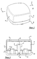
- the product simulating probe 50 is an integrated temperature measuring and transmitting device including a box-like housing 70 encapsulating a thermal mass 74 and a temperature sensing element 80 and including a wireless transmitter 82.
- the housing 70 includes a cover 72 secured to a base 86, and magnets 84 mounted to the cover 72 facilitate easy attachment of the probe 50 to the display case 22.
- the cover 72 is adhered to the base 86 to seal the thermal mass 74 therein.
- a bracket 85 may be used by securing the bracket 85 to the display case 22 and attaching the probe 50 by sliding the bracket into a complimentary slot 87 on the base 86 of the probe 50.
- the thermal mass 74 is a container housing a material having thermo-physical characteristics similar to food product. Because food product predominantly contains water, the thermo-physical simulating material is preferably either salt water or a solid material that has the same thermal characteristics as water, such as low-density polyethylene (LDPE) or propylene glycol.
- the container for the thermal mass is preferably a plastic bag, and most preferably a pliable polypropylene bag, sealably containing the simulating material. Alternatively, a more rigid material can be used, but should include a centrally disposed channel 77 for accommodating the temperature sensing element 80 in close proximity to the material having thermo-physical characteristics similar to food product.
- the thermal mass 74 is a 16-ounce (1-pint) sealed-plastic container filled with four percent (4%) salt water.
- the temperature-sensing element 80 is embedded in the center of the thermal mass 74 so that the temperature product probe 50 measures the simulated internal temperature of food products.
- the temperature-sensing element 80 is preferably a thermistor.
- a middle plate 78 seals the temperature sensing element 80 and transmitter 82 relative the thermal mass 74 and includes a transversely extending tube 76 that supports the temperature sensing element 80 within the channel 77 of the thermal mass 74.
- the pliable plastic material forms the channel 77 by accommodating the tube 76 within the thermal mass 74.
- a gasket 89 is disposed between the middle plate 78 and the base 86 to seal the space between the middle plate 78 and the bottom of the base 86 containing the transmitter 82.
- Fasteners 91 received through the base 86 secure the middle plate 78 to the base 86 through threaded reception in nut inserts 93 in-molded or secured to the middle plate 78.
- the wireless transmitter 82 preferably includes a signal-conditioning circuit, is mounted between the base 86 and the middle plate 85, and is connected to the temperature sensing element 80 via a wire 88.
- the wireless transmitter 82 is a radio frequency (RF) device that transmits parametric data.
- the wireless transmitter 82 is a transceiver capable of sending and receiving RF parametric data.
- the wireless transmitter 82 is a standalone transceiver or transmitter that can be positioned independently of other hardware, such as repeaters, operating on internal or external power, that retransmit at the same or different radio frequencies as the parametric data and control inputs and outputs, and one or more transmitters 82 or receivers 94 that are linked to the main controller 30. This is described in greater detail hereinbelow.
- the wireless transmitter 82 preferably operates on an internal power source, such as a battery, but can alternatively by powered by an external power source.
- the product simulating probe 50 monitors the performance of the display case 22.
- one probe 50 is placed within each display case 22.
- the product-simulating probe 50 wirelessly transmits simulated product temperature data to the receiver 94, which collects the temperature data and retransmits it to the main controller 30 via the communication bus 96.
- the main controller 30 logs and analyzes the temperature data, and controls the temperature of the display cases 22 based on the monitored temperature data.
- an alternative embodiment of the invention includes disposing a transmitter 82' (which, alternatively, can be a transceiver) apart from a product simulating probe 50' and then connecting the transmitter 82' to the probe 50' via a wire 84.
- the product simulating probe 50' does not include an internal transmitter 82, but is connected to an external transmitter 82' connected to the temperature sensing element 80 via the wire 84.
- a discharge air temperature sensor 48 can similarly be connected to the transmitter 82' for transmission of measured data.
- the wireless transmitter 82' is mounted externally on the display case 22; for example, mounted on the top of the display case 22. The method of transmitting the temperature data from the product simulating probe 50' to the main controller 30 remains the same as described above.
- a temperature display module 46 may alternatively be used as shown in Figure 7.
- the temperature display module 46 is preferably a TD3 Case Temperature Display, also offered by CPC, Inc. of Atlanta, Georgia.
- the display module 46 is preferably mounted in each refrigeration case 22, and is connected to the wireless transmitter 82'.
- Each module 46 preferably measures up to three (3) temperature signals, but more or fewer can be measured depending on the need. These measured signals include the case discharge air temperature measured by a discharge temperature sensor 48, the simulated product temperature measured by a product simulator temperature probe 50', and a defrost termination temperature measured by a defrost termination sensor 52.
- the display module 46 also includes an LED display 54 that can be configured to display any of the temperatures and/or case status (defrost/refrigeration/alarm).
- the display module 46 will measure the case discharge air temperature, via the discharge temperature sensor 48 and the product simulated temperature, via the product probe temperature sensor 50 and then wirelessly transmit this data to the main refrigeration controller 30 via the wireless transmitter 82', which transmits data to the receiver 94 connected to the main controller 30 via the communication bus 96. This information is logged and used for subsequent system control utilizing the novel methods discussed herein.
- the main controller 30 can be configured by the user to set alarm limits for each case 22, as well as defrosting parameters, based on temperature data measured by the probe 50, or discharge temperature sensor 48, or any other sensor including the defrost termination sensor 52, return air sensor, evaporator temperature or clean switch sensor.
- the main controller 30 preferably notifies a remotely located central monitoring station 100 via a communication bus 102, including LAN/WAN or remote dialup using, e.g., TCP/IP.
- the main controller 30 can notify a store manager or refrigeration service company via a telephone call or page using a modem connected to a telephone line.
- the alarm and defrost information can be transmitted from the main refrigeration controller 30 to the display module 46 for displaying the status on the LED display 54.
- a temperature control logic 70 is shown to control the electronic pressure regulator (ESR) 28 for the particular circuit 26 being analyzed.
- ESR electronic pressure regulator
- each electronic pressure regulator 28 is controlled by measuring the case temperature with respect to the particular circuit 26.
- each circuit A,B,C,D includes product-simulating probes 50, 50' that wirelessly transmit temperature data to the analog signal receiver 94.
- the receiver 94 measures the case temperature and transmits the data to the refrigeration controller 30 using the communication network 34.
- the temperature control logic or algorithm 70 is programmed into the refrigeration controller 30.
- the temperature control logic 110 may either receive case temperatures (T 1 , T 2 , T 3 ,...T n ) from each case 22 in the particular circuit 26 or a single temperature from one case 22 in the circuit 26. Should multiple temperatures be monitored, these temperatures (T 1 , T 2 , T 3 ,...T n ) are manipulated by an average/min/max temperature block 72. Block 72 can either be configured to take the average of each of the temperatures (T 1 , T 2 , T 3 ,...T n ) received from each of the cases 22. Alternatively, the average/min/max temperature block 112 may be configured to monitor the minimum and maximum temperatures from the cases 22 to select a mean value to be utilized or some other appropriate value.
- the temperature (T_ct) is applied to an error detector 114.
- the error detector 114 compares the desired circuit temperature set point (SP_ct) which is set by the user in the refrigeration controller 30 to the actual measured temperature (T_ct) to provide an error value (E_ct).
- this error value (E_ct) is applied to a PI/PID/Fuzzy Logic algorithm 108, which is a conventional refrigeration control algorithm, to determine a particular percent (%) valve opening (VO_ct) for the particular electronic pressure regulator (ESR) 28 being controlled via the ESR board 42. Further detail regarding the calculation of VO_ct is provided hereinbelow.
- each case temperature measurement sensor required connecting each display case 22 to the analog input board 38, which is generally located in the compressor room 6. This created a lot of wiring and high installation costs.
- the invention described herein overcomes this limitation by wirelessly arranging the transmission of temperature data from product simulating probes 50, 50', or from other temperature sensors including the discharge temperature sensor 48, defrost termination sensor 52, return air sensor, evaporator temperature or clean switch sensor, etc.
- a further improvement to this configuration is to use the display module 46, as shown in circuit A of Figure 1, as well as Figure 7.
- a temperature sensor within each case 22 passes the temperature information to the display module 46, which wirelessly transmits the data to the receiver 94, which sends the data to the controller 30.
- the temperature data is transferred directly from the refrigeration case 22 to the refrigeration controller 30 without the need for the analog input board 38, or for wiring the various sensors to the analog input board 38, thereby substantially reducing wiring and installation costs.
- a floating circuit temperature control logic 116 is illustrated based upon temperature measurements from the product-simulating probe 50, 50'.
- the floating circuit temperature control logic 116 begins at start block 118. From start block 118, the control logic proceeds to differential block 120.
- differential block 120 the average product simulation temperature for the past one-hour or other appropriate time period is subtracted from a maximum allowable product temperature to determine a difference (diff).
- measurements from the product probe 50 are preferably taken, for example, every ten seconds with a running average taken over a certain time period, such as one hour.
- the type of product being stored in the particular refrigeration case 22 generally controls the maximum allowable product temperature.
- a limit of 41°F is generally the maximum allowable temperature for maintaining meat in a refrigeration case 22.
- the maximum allowable product temperature can be set 5°F lower than this maximum (i.e., 36° for meat).
- the control logic 116 proceeds to determination block 122, determination block 124 or determination block 126.
- determination block 122 if the difference between the average product simulator temperature and the maximum allowable product temperature from differential block 120 is greater than 5° F, a decrease of the temperature set point for the particular circuit 26 by 5° F is performed at change block 128. From here, the control logic returns to start block 118. This branch identifies that the average product temperature is too warm, and therefore, needs to be cooled down.
- determination block 124 if the difference is greater than -5° F and less than 5° F, this indicates that the average product temperature is sufficiently near the maximum allowable product temperature and no change of the temperature set point is performed in block 130. Should the difference be less than -5° F as determined in determination block 126, an increase in the temperature set point of the circuit by 5°F is performed in block 132.
- the refrigeration case 22 may be run in a more efficient manner since the control criteria is determined based upon the product temperature and not the case temperature which is a more accurate indication of desired temperatures. It should further be noted that while a differential of 5°F has been identified in the control logic 116, those skilled in the art would recognize that a higher or a lower temperature differential, may be utilized to provide even further fine tuning and all that is required is a high and low temperature differential limit to float the circuit temperature. It should further be noted that by using the floating circuit temperature control logic 116 in combination with the floating suction pressure control logic 80 further energy efficiencies can be realized. Variations of the above apparatus and method are described in U.S. Patent Application No. 09/539,563, filed March 31, 2000, entitled “Method And Apparatus For Refrigeration System Control Using Electronic Evaporator Pressure Regulators," incorporated herein by reference.
- the refrigeration system 10 of the present invention is shown to preferably include a mode switch 150.
- the mode switch 150 is shown in Figure 10 to be integrated with the display module 46. It should be noted, however, that the mode switch 150 is not limited to integration with the display module 46 and may be mounted anywhere on, in or near its corresponding refrigeration case 22.
- the mode switch 150 can be switched from a first position, corresponding to a first mode, and a second position, corresponding to a second mode.
- the first mode can be characterized as a "normal" operation mode while the second mode can be characterized as a "clean" mode.
- the mode switch 150 is designed to signal the refrigerator controller 30 that a refrigeration case 22 is being cleaned. Upon activation of the mode switch 150, a unique message is transmitted to the refrigerator controller 30. If the message is interpreted by the refrigerator controller 30 as a cleaning signal, no temperature data will be recorded by the refrigeration controller 30 for the particular refrigerator case 22.
- each refrigerator case 22 is independently controlled by its own mode switch 150.
- the mode switch may be associated with a set of refrigerator cases 22.
- a visual detection means is preferably associated with each mode switch 150.
- the visual detection means 152 enables a user to determine the operating mode of a particular refrigerator case 22 without requiring the user to access the refrigerator controller 30.
- the visual detection means 152 may include the switch position, a light emitting diode (LED), a liquid crystal display (LCD) or a lamp.
- the type of visual indicator to be implemented will depend on a particular design.
- the transmitters 82,82' for this wireless system are preferably low power, which results in a limited transmission range for sending messages to and from the RF sensors 50,50' and the RF receiver 94.
- the RF receiver 94 is ideally located closer to the RF sensors 50,50'.
- locating the RF receiver 94 near the RF sensors 50, 50' is not always possible, particularly with larger systems deployed in large buildings and warehouses. For such applications, an RF repeater is useful.
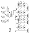
- the RF monitoring system 160 implements a plurality of RF repeaters 162 to overcome the limited transmission range described above.
- Each RF repeater 162 acts as a bridge between the receiver 94 and the product simulating probes 50,50' for re-sending messages back and forth.
- the RF repeaters 162 listen for messages then boost the signal back to the receiver 94.
- message "collisions" could occur if multiple RF repeaters 162 started sending a message to the receiver 94 at the same time or at overlapping times.
- the receiver 94 uses a polling scheme to collect data from the RF repeaters 162 and to relay request information back to the product simulating probes 50,50' on the input side of the RF repeater.
- the RF repeater 162 and the receiver 94 are actually low-power transceivers that must meet certain requirements of the FCC (e.g. Parts 15.247 and 15.249).
- the receiver 94 initially sends a message or "polling" signal to a specific RF repeater 162, signaling the RF repeater 162 to send all pending data. Upon receipt of this signal, the RF repeater 162 sends all of its pending data to the receiver 94 including an ALL PENDING DATA SENT message. This message signals the receiver 94 that the particular RF repeater 162 has sent all of its pending data. The same steps are then repeated for each RF repeater 162. If the receiver 94 does not receive a return message within one (1) second, it will re-send the SEND ALL PENDING DATA signal two more times to ensure that the particular RF repeater 162 has adequate time to begin data transmission.
- the receiver 94 If the receiver 94 does not receive a return message, the receiver 94 will flag an error and poll the next RF repeater 162. Once having received the data, the receiver 94 routes the data to the appropriate refrigerator controller 30. This is achieved by routing the message through an input/output (I/O) net 164 corresponding to a particular refrigerator controller 30.
- the individual I/O nets 164 each comprise a gateway 166, an analog input board 168 and a relay output board 170.
- the analog input board 168 and relay output board are generally used for communicating information from and to, respectively, other components which do not operate with the wireless system.
- the gateway 166 acts as a bridge between the "wireless" and "normal” communication systems by taking data from the receiver 94 and formatting it for a particular area controller 30.
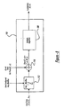
- the refrigerator system 180 includes a control loop 182 and a refrigerator loop 184.
- the control loop 182 generally includes a refrigerator controller 30', an I/O board 32', a receiver 94' and a wireless air temperature sensor 182.
- the refrigerator loop 184 generally includes a compressor 188, an evaporator 190 and a condenser 192.
- the wireless air temperature sensor 186 is disposed near the evaporator 190.
- Regular operation of the refrigeration system 180 includes daily defrosting of the evaporator 190.
- Defrosting of the evaporator 190 lasts for a specified duration of time and is preferably accomplished by a heater 191 using an electric heating element, hot gas, or hot air.
- defrost is terminated prior to the specified time duration if the temperature of the evaporator 190 goes above a specific value (e.g. 45°F).
- a preferred evaporator defrost method of the present invention uses the wireless air temperature sensor 186 (see Figure 7) for making a defrost determination decision.
- the wireless temperature sensor could include a thermostat switch of a type known in the art.
- the controller 30' stops refrigeration flow to the evaporation 190 and initiates the heater 191, if any. Where a heater is not used for defrost, simply stopping refrigeration supply to the evaporator 190 initiates defrost by allowing the temperature of the evaporator 190 to rise.
- the wireless air temperature sensor 186 monitors the temperature of the evaporator 190. This data is sent to the refrigerator controller 30' through the receiver 94'. The refrigerator controller 30' then determines the appropriate output of the compressor 188 and sends a signal through the I/O board 32' to accordingly adjust the operation of the compressor 188.
- the possible temperature control algorithms include dead-band control (DB), proportional/integral (PI) logic, proportional/integral/differentiation (PID) logic and fuzzy logic (FL).
- FIG. 13 details the dead-band control logic for controlling the evaporator temperature within the refrigerator case 22.
- the evaporator temperature (T_ct) is initially measured by the wireless air temperature sensor 186 and compared with the set point temperature (SP_ct).
- the measured temperature can be the temperature relating to a single display case or can be one of either a maximum temperature, a minimum temperature, or an average temperature for a series of display cases in a circuit.
- the error (E-ct) is calculated as the difference between the measured evaporator temperature (T_ct) and the set point temperature (SP_ct).
- DB is a temperature range (e.g.
- An integral, or summation, compressor control output (I) is also determined.
- the PI logic is the same as described above for the PID logic, with the exception that the D compressor value is not considered (i.e., set to zero).
- E_ct is sampled over a period of time.
- the controller 30' selects one of either an average, minimum, or maximum value for E_ct during the sample period.
- the preferred temperature value is preprogrammed into the controller 30'.
- the controller 30' also determines an error rate, E_rt, for the sample period.
- E_rt is the rate at which the E_ct is either increasing or decreasing over the sample period.
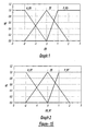
- E_ct and E_rt are then used as inputs into the FL process.
- the first step is termed "fuzzification", during which, membership functions are determined as a function of E_ct and E_rt, referencing their respective graphs.
- the membership functions for E_ct include: negative error (N_ER), zero error (ZE) and positive error (P_ER).
- the changes in output are defined as: Changes in Output Abbreviation % Change Big Negative Change BNC -30 Medium Negative Change MNC -20 Small Negative Change SNC -10 No Change NC 0 Small Positive Change SPC 10 Medium Positive Change MPC 20 Big Negative Change BPC 30
- the change in output corresponding to the maximum comparison value is chosen and the other is not considered. For example, suppose MNC was the result for two of the above comparisons. The MNC change in output corresponding to the highest membership function value is used and the other is not considered in the subsequent calculations.
- the final step includes a "defuzzification” process which calculates a percentage change in compressor control output as a function of the "minimum” comparison values and the change in output values.
- the controller 30' may be controlling more than one compressor for a given refrigeration system.
Landscapes
- Engineering & Computer Science (AREA)
- Physics & Mathematics (AREA)
- General Physics & Mathematics (AREA)
- Automation & Control Theory (AREA)
- Chemical & Material Sciences (AREA)
- Combustion & Propulsion (AREA)
- Mechanical Engineering (AREA)
- Thermal Sciences (AREA)
- General Engineering & Computer Science (AREA)
- Computer Networks & Wireless Communication (AREA)
- Devices That Are Associated With Refrigeration Equipment (AREA)
- Cold Air Circulating Systems And Constructional Details In Refrigerators (AREA)
Applications Claiming Priority (4)
| Application Number | Priority Date | Filing Date | Title |
|---|---|---|---|
| US564173 | 2000-05-03 | ||
| US09/564,173 US6502409B1 (en) | 2000-05-03 | 2000-05-03 | Wireless method and apparatus for monitoring and controlling food temperature |
| US09/702,993 US6378315B1 (en) | 2000-05-03 | 2000-10-31 | Wireless method and apparatus for monitoring and controlling food temperature |
| US702993 | 2000-10-31 |
Publications (2)
| Publication Number | Publication Date |
|---|---|
| EP1152316A2 true EP1152316A2 (fr) | 2001-11-07 |
| EP1152316A3 EP1152316A3 (fr) | 2005-02-16 |
Family
ID=27073482
Family Applications (5)
| Application Number | Title | Priority Date | Filing Date |
|---|---|---|---|
| EP10011857A Ceased EP2287700A3 (fr) | 2000-05-03 | 2001-05-02 | Procédé et appareil sans fil pour la surveillance et le contrôle de la température des aliments |
| EP01304035A Withdrawn EP1152316A3 (fr) | 2000-05-03 | 2001-05-02 | Procédé et dispositif sans fil de supervision et contrôle de la température d'aliments |
| EP07008375A Withdrawn EP1814010A3 (fr) | 2000-05-03 | 2001-05-02 | Procédé et appareil sans fil pour la surveillance et le contrôle de la température des aliments |
| EP10011856A Withdrawn EP2287699A3 (fr) | 2000-05-03 | 2001-05-02 | Procédé et appareil sans fil pour la surveillance et le contrôle de la température des aliments |
| EP01304034A Ceased EP1152315A3 (fr) | 2000-05-03 | 2001-05-02 | Procédé et dispositif sans fil de supervision et contrôle de la température d'aliments |
Family Applications Before (1)
| Application Number | Title | Priority Date | Filing Date |
|---|---|---|---|
| EP10011857A Ceased EP2287700A3 (fr) | 2000-05-03 | 2001-05-02 | Procédé et appareil sans fil pour la surveillance et le contrôle de la température des aliments |
Family Applications After (3)
| Application Number | Title | Priority Date | Filing Date |
|---|---|---|---|
| EP07008375A Withdrawn EP1814010A3 (fr) | 2000-05-03 | 2001-05-02 | Procédé et appareil sans fil pour la surveillance et le contrôle de la température des aliments |
| EP10011856A Withdrawn EP2287699A3 (fr) | 2000-05-03 | 2001-05-02 | Procédé et appareil sans fil pour la surveillance et le contrôle de la température des aliments |
| EP01304034A Ceased EP1152315A3 (fr) | 2000-05-03 | 2001-05-02 | Procédé et dispositif sans fil de supervision et contrôle de la température d'aliments |
Country Status (9)
| Country | Link |
|---|---|
| US (5) | US6502409B1 (fr) |
| EP (5) | EP2287700A3 (fr) |
| KR (3) | KR100826217B1 (fr) |
| AR (2) | AR028077A1 (fr) |
| AU (2) | AU775199B2 (fr) |
| BR (2) | BRPI0102200B1 (fr) |
| CA (2) | CA2345891C (fr) |
| IL (2) | IL142927A0 (fr) |
| MX (2) | MXPA01004408A (fr) |
Cited By (14)
| Publication number | Priority date | Publication date | Assignee | Title |
|---|---|---|---|---|
| EP1497778A4 (fr) * | 2002-03-21 | 2005-05-04 | Lifevine Inc | Systeme et procede de suivi de soins de sante |
| EP1479988A3 (fr) * | 2003-05-23 | 2007-10-31 | Indesit Company S.p.A. | Appareil ménager, en particulier appareil frigorifique, avec un système de contrôle utilisant des capteurs basés sur la technologie RFID |
| EP2434240A1 (fr) * | 2010-09-28 | 2012-03-28 | A.P. Møller - Mærsk A/S | Procédé et système pour le contrôle de la température dans des espaces de stockage réfrigérés |
| WO2012041779A3 (fr) * | 2010-09-28 | 2012-06-07 | A.P. Møller - Mærsk A/S | Procédé et système de régulation de température dans des espaces de stockage réfrigérés |
| DE102011016735A1 (de) * | 2011-04-11 | 2012-10-11 | Liebherr-Hausgeräte Ochsenhausen GmbH | Kühl- und/oder Gefriergerät |
| WO2013150397A1 (fr) * | 2012-04-02 | 2013-10-10 | Gorenje Gospodinjski Aparati, D.D. | Couvercle de pot ayant un dispositif de capteur |
| CN103620359A (zh) * | 2011-07-18 | 2014-03-05 | 莴苣箱有限责任公司 | 食品用热模拟探测针 |
| CN104155956A (zh) * | 2014-08-19 | 2014-11-19 | 东华大学 | 一种基于Wi-Fi的无线温度远程监控系统 |
| EP2454533A4 (fr) * | 2009-07-13 | 2015-10-21 | Carrier Corp | Système de réfrigération de transport, unité de réfrigération de transport et procédé pour ceux-ci |
| CN105115242A (zh) * | 2015-09-07 | 2015-12-02 | 合肥美的电冰箱有限公司 | 一种具有可活动的传感器的冰箱 |
| WO2016131609A1 (fr) * | 2015-02-18 | 2016-08-25 | BSH Hausgeräte GmbH | Appareil électroménager frigorifique comportant une unité de détection sans fil |
| WO2017081257A1 (fr) * | 2015-11-12 | 2017-05-18 | Empa Eidgenössische Materialprüfungs- Und Forschungsanstalt | Produit horticole artificiel à capteur de température |
| BE1023856B1 (nl) * | 2016-02-11 | 2017-08-22 | Efoodconsult Bvba | Isothermische box met koelplaten, ingebouwde draadloze temperatuursensor en intelligente cloudapplicatie |
| US9958198B2 (en) | 2009-07-13 | 2018-05-01 | Carrier Corporation | Embedded cargo sensors for a refrigeration system |
Families Citing this family (143)
| Publication number | Priority date | Publication date | Assignee | Title |
|---|---|---|---|---|
| US6505475B1 (en) | 1999-08-20 | 2003-01-14 | Hudson Technologies Inc. | Method and apparatus for measuring and improving efficiency in refrigeration systems |
| GB9926952D0 (en) * | 1999-11-16 | 2000-01-12 | Universal Master Products Limi | Food simulant temperature sensing device |
| US7062361B1 (en) * | 2000-05-02 | 2006-06-13 | Mark E. Lane | Method and apparatus for controlling power consumption |
| US6502409B1 (en) * | 2000-05-03 | 2003-01-07 | Computer Process Controls, Inc. | Wireless method and apparatus for monitoring and controlling food temperature |
| US6742349B1 (en) * | 2000-05-16 | 2004-06-01 | Sanyo Electric Co., Ltd. | Equipment sensing system and equipment control device |
| JP2002092208A (ja) * | 2000-09-13 | 2002-03-29 | Miura Co Ltd | 熱供給設備の保守管理システム |
| US6324854B1 (en) * | 2000-11-22 | 2001-12-04 | Copeland Corporation | Air-conditioning servicing system and method |
| KR20010074005A (ko) * | 2000-11-22 | 2001-08-04 | 안병진 | 식품 위해 요소 중점 관리 시스템 |
| JP3581121B2 (ja) * | 2000-12-21 | 2004-10-27 | 株式会社低温食品加工技術研究所 | 水産物市場の品質保持装置とその方法及び該水産物市場のセリ市場システム |
| US6725180B2 (en) * | 2001-01-12 | 2004-04-20 | Ingersoll-Rand Company | Environmental monitoring system |
| US6675591B2 (en) * | 2001-05-03 | 2004-01-13 | Emerson Retail Services Inc. | Method of managing a refrigeration system |
| US6668240B2 (en) * | 2001-05-03 | 2003-12-23 | Emerson Retail Services Inc. | Food quality and safety model for refrigerated food |
| US6549135B2 (en) * | 2001-05-03 | 2003-04-15 | Emerson Retail Services Inc. | Food-quality and shelf-life predicting method and system |
| US6892546B2 (en) | 2001-05-03 | 2005-05-17 | Emerson Retail Services, Inc. | System for remote refrigeration monitoring and diagnostics |
| CN100414568C (zh) * | 2001-07-25 | 2008-08-27 | 阿特林克斯美国公司 | 用于有效率调节数据发送的方法和系统 |
| JP2003130420A (ja) * | 2001-10-26 | 2003-05-08 | Daikin Ind Ltd | 空気調和装置の制御システム及び空気調和装置 |
| US6889173B2 (en) | 2002-10-31 | 2005-05-03 | Emerson Retail Services Inc. | System for monitoring optimal equipment operating parameters |
| JP4239574B2 (ja) * | 2002-11-29 | 2009-03-18 | 日新イオン機器株式会社 | アラーム管理方法およびその装置 |
| US8463441B2 (en) | 2002-12-09 | 2013-06-11 | Hudson Technologies, Inc. | Method and apparatus for optimizing refrigeration systems |
| KR20040052096A (ko) * | 2002-12-13 | 2004-06-19 | 엘지전자 주식회사 | 김치냉장고 및 그의 온도제어방법 |
| US20040226308A1 (en) * | 2003-05-16 | 2004-11-18 | Serge Dube | Method for controlling evaporation temperature in a multi-evaporator refrigeration system |
| CN100489419C (zh) * | 2003-08-25 | 2009-05-20 | 计算机程序控制公司 | 制冷系统和方法 |
| CN101713397B (zh) * | 2003-12-30 | 2014-07-09 | 艾默生环境优化技术有限公司 | 压缩机保护和诊断系统 |
| US7240501B2 (en) * | 2004-02-11 | 2007-07-10 | Door Miser, Llc | System for preventing condensation on refrigerator doors and frames |
| US20060026975A1 (en) * | 2004-02-11 | 2006-02-09 | John Bunch | Wireless system for preventing condensation on refrigerator doors and frames |
| US6983622B2 (en) * | 2004-04-20 | 2006-01-10 | Danfoss Commercial Compressors | Gas distribution device |
| US7412842B2 (en) * | 2004-04-27 | 2008-08-19 | Emerson Climate Technologies, Inc. | Compressor diagnostic and protection system |
| US8707861B2 (en) * | 2004-08-02 | 2014-04-29 | John Bean Technologies Corporation | Dry food pasteurization apparatus and method |
| US7275377B2 (en) | 2004-08-11 | 2007-10-02 | Lawrence Kates | Method and apparatus for monitoring refrigerant-cycle systems |
| US20060150662A1 (en) * | 2005-01-13 | 2006-07-13 | Samsung Electronics Co., Ltd. | Refrigerator and method for controlling the same |
| ATE553422T1 (de) * | 2005-02-21 | 2012-04-15 | Computer Process Controls Inc | Kontroll- und beobachtungssystem für unternehmen |
| EP1980805B1 (fr) * | 2005-03-18 | 2009-09-02 | Danfoss A/S | Procédé de contrôle d'un système de réfrigération |
| US7367198B2 (en) * | 2005-07-07 | 2008-05-06 | Hussmann Corporation | Method of control for a refrigerated merchandiser |
| US20070058315A1 (en) * | 2005-09-09 | 2007-03-15 | Maddox Harold D | Controlling spas |
| US20070058634A1 (en) * | 2005-09-09 | 2007-03-15 | Vipul Gupta | Interaction with wireless sensor devices |
| US20070089435A1 (en) * | 2005-10-21 | 2007-04-26 | Abtar Singh | Predicting maintenance in a refrigeration system |
| US20070089436A1 (en) * | 2005-10-21 | 2007-04-26 | Abtar Singh | Monitoring refrigerant in a refrigeration system |
| US7594407B2 (en) | 2005-10-21 | 2009-09-29 | Emerson Climate Technologies, Inc. | Monitoring refrigerant in a refrigeration system |
| US7665315B2 (en) * | 2005-10-21 | 2010-02-23 | Emerson Retail Services, Inc. | Proofing a refrigeration system operating state |
| US7596959B2 (en) | 2005-10-21 | 2009-10-06 | Emerson Retail Services, Inc. | Monitoring compressor performance in a refrigeration system |
| US7752853B2 (en) | 2005-10-21 | 2010-07-13 | Emerson Retail Services, Inc. | Monitoring refrigerant in a refrigeration system |
| US7752854B2 (en) * | 2005-10-21 | 2010-07-13 | Emerson Retail Services, Inc. | Monitoring a condenser in a refrigeration system |
| US20070093732A1 (en) * | 2005-10-26 | 2007-04-26 | David Venturi | Vibroacoustic sound therapeutic system and method |
| US7412837B2 (en) * | 2006-02-23 | 2008-08-19 | Dometic Sweden Ab | Method for use in controlling an absorption refrigerating system, and an absorption refrigerator |
| US7658334B2 (en) * | 2006-04-05 | 2010-02-09 | Smartfreeze S.R.L. | System for the real time inventory and localization of refrigerating containers and related method |
| US7797957B2 (en) * | 2006-04-12 | 2010-09-21 | Hussmann Corporation | Methods and apparatus for linearized temperature control of commercial refrigeration systems |
| DE102006029935A1 (de) * | 2006-06-29 | 2008-01-03 | Wurm Gmbh & Co. Kg Elektronische Systeme | Temperaturmesseinheit |
| US8590325B2 (en) | 2006-07-19 | 2013-11-26 | Emerson Climate Technologies, Inc. | Protection and diagnostic module for a refrigeration system |
| US20080120188A1 (en) * | 2006-08-15 | 2008-05-22 | Jason Mobley | Food temperature collection, storage and retrieval system |
| US8033716B1 (en) | 2006-08-23 | 2011-10-11 | Troy Marcus Tandy | Refrigeration temperature monitoring system and associated temperature display |
| US20080216494A1 (en) | 2006-09-07 | 2008-09-11 | Pham Hung M | Compressor data module |
| US7711515B2 (en) * | 2006-10-26 | 2010-05-04 | Current Energy Controls, Lp | System and method for automated parameter measurement |
| EP1927818B1 (fr) * | 2006-11-30 | 2016-01-20 | Whirlpool Corporation | Méthode de commande d'un processus de congélation rapide d'aliments dans un appareil de réfrigération et appareil de réfrigération configuré pour la mise en oeuvre de cette méthode |
| US20080148751A1 (en) * | 2006-12-12 | 2008-06-26 | Timothy Dean Swofford | Method of controlling multiple refrigeration devices |
| US7878008B1 (en) * | 2006-12-18 | 2011-02-01 | Sprint Communications Company L.P. | Smart rack and intelligent wireless climate sensors |
| US20080159910A1 (en) * | 2006-12-29 | 2008-07-03 | Dick Paul H | Shipping container ozonation system |
| US20080274240A1 (en) * | 2007-05-03 | 2008-11-06 | Omar Germouni | Adaptive controller and expert system food processing |
| US20090037142A1 (en) | 2007-07-30 | 2009-02-05 | Lawrence Kates | Portable method and apparatus for monitoring refrigerant-cycle systems |
| US8393169B2 (en) | 2007-09-19 | 2013-03-12 | Emerson Climate Technologies, Inc. | Refrigeration monitoring system and method |
| US8160827B2 (en) | 2007-11-02 | 2012-04-17 | Emerson Climate Technologies, Inc. | Compressor sensor module |
| US9140728B2 (en) * | 2007-11-02 | 2015-09-22 | Emerson Climate Technologies, Inc. | Compressor sensor module |
| US8020391B2 (en) | 2007-11-28 | 2011-09-20 | Hill Phoenix, Inc. | Refrigeration device control system |
| US20090299953A1 (en) * | 2008-06-02 | 2009-12-03 | Ted Wayne Sunderland | Merchandiser with automated report generation system |
| WO2010008343A1 (fr) * | 2008-07-18 | 2010-01-21 | Sensimesh Pte Ltd | Appareil et procédé pour surveiller des contenants frigorifiques |
| GB2465019B (en) * | 2008-11-06 | 2015-08-12 | Universal Master Products Ltd | Food simulant material for temperature control sensor |
| US8417386B2 (en) * | 2008-11-17 | 2013-04-09 | Trane International Inc. | System and method for defrost of an HVAC system |
| US8248252B2 (en) | 2008-11-21 | 2012-08-21 | Schechter Tech, Llc | Remote monitoring system |
| SG10201501769RA (en) * | 2009-01-13 | 2015-05-28 | Emd Millipore Corp | Improved biomaterial freezing |
| GB0902418D0 (en) * | 2009-02-16 | 2009-04-01 | Dfx Technology Ltd | An energy-saving control system with remote sensing |
| MX2011012546A (es) | 2009-05-29 | 2012-10-03 | Emerson Retail Services Inc | Sistema y metodo para monitorear y evaluar modificaciones de parametros operativos de equipo. |
| USD614974S1 (en) | 2009-09-29 | 2010-05-04 | Golberg Wayne C | Temperature monitor |
| WO2011041780A2 (fr) * | 2009-10-02 | 2011-04-07 | The Controls Group, Inc. | Retrait d'une substance congelée accumulée à partir d'une unité de refroidissement |
| US8522565B1 (en) * | 2009-10-20 | 2013-09-03 | The Veracity Group, Inc. | Refrigerator with removable cooling unit |
| CA2714227C (fr) * | 2010-06-18 | 2011-10-25 | Guest Tek Interactive Entertainment Ltd. | Serveur de profils d'utilisateur concu pour donner a l'interesse une experience de divertissement personnalisee par le truchement de divers dispositifs de divertissement et methode connexe |
| CN102566622B (zh) * | 2010-12-30 | 2014-03-19 | 泰州乐金电子冷机有限公司 | 冰箱用温度调节装置 |
| WO2012106520A1 (fr) * | 2011-02-02 | 2012-08-09 | Oscomp Systems Inc. | Appareil et procédés pour réguler l'écoulement de matière à l'aide d'une soupape actionnée en fonction de la température |
| EP2681497A4 (fr) | 2011-02-28 | 2017-05-31 | Emerson Electric Co. | Solutions de contrôle et de diagnostic d'un système hvac destinées à des habitations |
| EP2505978B1 (fr) * | 2011-03-28 | 2017-05-10 | Nxp B.V. | Capteur de température, dispositif électronique et procédé de mesure de la température |
| CN102261807B (zh) * | 2011-05-09 | 2013-11-06 | 合肥美的电冰箱有限公司 | 用于多个制冷设备的通用控制方法及系统、制冷设备 |
| WO2012166984A1 (fr) | 2011-06-01 | 2012-12-06 | Pfi Acquisition, Inc. | Appareil pour alimenter un dispositif accessoire dans un conteneur réfrigéré |
| US8779926B2 (en) | 2011-12-29 | 2014-07-15 | Schechter Tech, Llc | Presenting information regarding conditions of an environment with a visual representation of the environment |
| US8964338B2 (en) | 2012-01-11 | 2015-02-24 | Emerson Climate Technologies, Inc. | System and method for compressor motor protection |
| WO2013143560A1 (fr) | 2012-03-29 | 2013-10-03 | Red Bull Gmbh | Dispositif de conservation d'objets comportant un dispositif d'état de remplissage et un dispositif de détection d'utilisateur |
| CN104350527A (zh) | 2012-03-29 | 2015-02-11 | 红牛有限公司 | 具有用于检测存放设备的取出、装载和/或装载状态的装载状态检测设备的物品存放设备 |
| US20150145678A1 (en) | 2012-03-29 | 2015-05-28 | Red Bull Gmbh | Computer Network for Monitoring and Controlling Storage Facilities Comprising a Load State Device and a User Detection Device |
| US9480177B2 (en) | 2012-07-27 | 2016-10-25 | Emerson Climate Technologies, Inc. | Compressor protection module |
| US9310439B2 (en) | 2012-09-25 | 2016-04-12 | Emerson Climate Technologies, Inc. | Compressor having a control and diagnostic module |
| US9064389B1 (en) | 2012-11-13 | 2015-06-23 | e-Control Systems, Inc. | Intelligent sensor for an automated inspection system |
| CN103017919B (zh) * | 2012-12-27 | 2015-06-17 | 合肥华凌股份有限公司 | 感温组件和具有该感温组件的制冷设备 |
| US11493262B2 (en) | 2013-01-18 | 2022-11-08 | Triteq Lock And Security, L.L.C. | Cooler lock |
| WO2014144446A1 (fr) | 2013-03-15 | 2014-09-18 | Emerson Electric Co. | Diagnostic et système de télésurveillance de chauffage, de ventilation et de climatisation |
| US9803902B2 (en) | 2013-03-15 | 2017-10-31 | Emerson Climate Technologies, Inc. | System for refrigerant charge verification using two condenser coil temperatures |
| US9551504B2 (en) | 2013-03-15 | 2017-01-24 | Emerson Electric Co. | HVAC system remote monitoring and diagnosis |
| CA2908362C (fr) | 2013-04-05 | 2018-01-16 | Fadi M. Alsaleem | Systeme de pompe a chaleur a diagnostique de charge de fluide refrigerant |
| US10018400B2 (en) | 2013-08-13 | 2018-07-10 | Lennox Industries Inc. | Defrost operation management in heat pumps |
| US9470587B1 (en) | 2013-08-16 | 2016-10-18 | Cooper-Atkins Corporation | Solid thermal simulator sensing device |
| CN203480348U (zh) * | 2013-10-09 | 2014-03-12 | 健鑫仪器有限公司 | 温控调节装置 |
| US9767232B2 (en) | 2014-01-30 | 2017-09-19 | Schechter Tech, Llc | Temperature monitoring with simulated thermal buffer computed at a base station |
| US9500532B2 (en) | 2014-01-30 | 2016-11-22 | Schechter Tech, Llc | Temperature monitoring with simulated thermal buffer |
| US9797785B2 (en) | 2014-06-04 | 2017-10-24 | Magnum Energy Solutions, LLC | Environmental condition surveillance and methods thereof |
| US10085584B2 (en) | 2014-06-09 | 2018-10-02 | Whirlpool Corporation | Method of regulating temperature for sous vide cooking and apparatus therefor |
| DE102014112251A1 (de) * | 2014-08-26 | 2016-03-03 | Vorwerk & Co. Interholding Gmbh | Automatische Verarbeitung eines Nahrungsmittels |
| US9752810B1 (en) | 2014-10-29 | 2017-09-05 | Versid, Inc. | Refrigeration unit temperature alarm using thermal properties of food to eliminate false alarms |
| PT3056882T (pt) * | 2015-02-13 | 2020-03-04 | Vorwerk Co Interholding | Método para medição de uma temperatura dentro de um robô de cozinha |
| US10330099B2 (en) | 2015-04-01 | 2019-06-25 | Trane International Inc. | HVAC compressor prognostics |
| US9644847B2 (en) | 2015-05-05 | 2017-05-09 | June Life, Inc. | Connected food preparation system and method of use |
| US10739013B2 (en) | 2015-05-05 | 2020-08-11 | June Life, Inc. | Tailored food preparation with an oven |
| US9247322B1 (en) | 2015-05-29 | 2016-01-26 | Schechter Tech, Llc | Low-power user interface device for environmental monitoring system |
| US12222107B2 (en) | 2015-06-01 | 2025-02-11 | June Life, Llc | Thermal management system and method for a connected oven |
| WO2016201009A1 (fr) | 2015-06-08 | 2016-12-15 | Hussmann Corporation | Système d'affichage de produits alimentaires intégrant des services du détaillant et l'engagement du consommateur |
| CN105091498A (zh) * | 2015-08-10 | 2015-11-25 | 惠而浦(中国)股份有限公司 | 一种无显示屏的电控冰箱控制方法 |
| WO2017161123A1 (fr) * | 2016-03-18 | 2017-09-21 | Carrier Corporation | Système de transport de marchandises pour produits périssables |
| GB2566175A (en) * | 2016-04-13 | 2019-03-06 | Shoari Arian | Apparatus and methods for hygiene monitoring in restaurants and grocery superstores |
| US10401237B2 (en) | 2016-05-13 | 2019-09-03 | Digi International Inc. | Environmental sensor certification system |
| KR101843639B1 (ko) * | 2016-06-09 | 2018-05-14 | 엘지전자 주식회사 | 상황인식에 기반하여 신선도를 관리하는 냉장고, 서버, 포터블 장치 및 신선도를 관리하는 방법 |
| US10868857B2 (en) | 2017-04-21 | 2020-12-15 | Johnson Controls Technology Company | Building management system with distributed data collection and gateway services |
| US10739028B2 (en) * | 2017-06-09 | 2020-08-11 | Johnson Controls Technology Company | Thermostat with efficient wireless data transmission |
| US10333810B2 (en) | 2017-06-09 | 2019-06-25 | Johnson Controls Technology Company | Control system with asynchronous wireless data transmission |
| US10989464B2 (en) | 2017-07-20 | 2021-04-27 | Guido Dalmolin | System, method, and apparatus for monitoring refrigeration units |
| US11725877B2 (en) | 2017-07-20 | 2023-08-15 | Guido Dalmolin | System, method, and apparatus for monitoring refrigeration units |
| US10641532B2 (en) * | 2017-07-20 | 2020-05-05 | Guido Dalmolin | System, method, and apparatus for monitoring refrigeration units |
| US10648728B2 (en) * | 2017-09-29 | 2020-05-12 | Nxp Usa, Inc. | Multifunctional radio frequency systems and methods for UV sterilization, air purification, and defrost operations |
| US10955182B2 (en) | 2017-11-07 | 2021-03-23 | FreshRealm, LLC | Dynamic packing system |
| CN107806547A (zh) * | 2017-11-17 | 2018-03-16 | 安徽翼迈科技股份有限公司 | 具有gprs的一种采集器 |
| US11116050B1 (en) | 2018-02-08 | 2021-09-07 | June Life, Inc. | High heat in-situ camera systems and operation methods |
| US10723202B2 (en) | 2018-03-30 | 2020-07-28 | Thermo King Corporation | Systems and methods for coordinated control of multiple transport refrigeration systems |
| US10596878B2 (en) | 2018-03-30 | 2020-03-24 | Thermo King Corporation | Systems and methods for management of eTRU |
| EP3790818A1 (fr) * | 2018-05-11 | 2021-03-17 | Ecolab USA, Inc. | Système d'hygiène pour contenant portatif d'aliments emballés |
| CN109539641A (zh) * | 2018-10-17 | 2019-03-29 | 珠海格力电器股份有限公司 | 电子膨胀阀控制系统、控制方法及空调机组 |
| US11058132B2 (en) | 2019-11-20 | 2021-07-13 | June Life, Inc. | System and method for estimating foodstuff completion time |
| CN113157015B (zh) * | 2020-01-22 | 2022-05-24 | 广州汽车集团股份有限公司 | 热管理系统测试方法、平台、计算机设备及可读存储介质 |
| WO2021184003A1 (fr) | 2020-03-13 | 2021-09-16 | June Life, Inc. | Procédé et système de maintenance de capteurs |
| US11593717B2 (en) | 2020-03-27 | 2023-02-28 | June Life, Inc. | System and method for classification of ambiguous objects |
| CN111780894B (zh) * | 2020-07-06 | 2021-06-29 | 中国原子能科学研究院 | 放射性样品稳定热功率的实时追踪测量方法 |
| US12185862B2 (en) | 2020-08-14 | 2025-01-07 | June Life Llc | System and method for targeted heating element control |
| US11796248B2 (en) * | 2020-10-15 | 2023-10-24 | Haier Us Appliance Solutions, Inc. | Temperature probe for a refrigerator appliance |
| USD1007224S1 (en) | 2021-06-11 | 2023-12-12 | June Life, Inc. | Cooking vessel |
| USD978600S1 (en) | 2021-06-11 | 2023-02-21 | June Life, Inc. | Cooking vessel |
| CN114047730B (zh) * | 2021-10-27 | 2023-10-27 | 华电西港发电有限公司 | 一种高效省能火电厂发电生产优化控制装置 |
| CN114791749B (zh) * | 2021-12-27 | 2023-05-05 | 中国船舶工业综合技术经济研究院 | 一种局部天气情况模拟体验的隔离密闭胶囊舱 |
| US12276551B2 (en) | 2022-01-24 | 2025-04-15 | Thermco Products, Inc. | Wireless temperature monitoring buffering sensor and system |
| EP4421415B1 (fr) * | 2023-02-22 | 2025-02-12 | Thermo King LLC | Commande d'un circuit de réfrigération |
| KR102844527B1 (ko) * | 2023-05-17 | 2025-08-11 | (주)가람이엔티 | 냉장고용 온도 모니터링 시스템 |
Family Cites Families (44)
| Publication number | Priority date | Publication date | Assignee | Title |
|---|---|---|---|---|
| US2923786A (en) * | 1958-02-28 | 1960-02-02 | Donald R Jones | Dial thermometer alarm device |
| US3343151A (en) * | 1964-07-13 | 1967-09-19 | Clark Equipment Co | Refrigeration warning system |
| US3690175A (en) | 1971-04-05 | 1972-09-12 | Clark Equipment Co | Mechanism for predicting food temperatures |
| US3964313A (en) * | 1974-08-21 | 1976-06-22 | Swift & Company | Canned food recyclable thermal simulator |
| US4003124A (en) * | 1974-08-21 | 1977-01-18 | Swift And Company Limited | Method of making canned food recyclable thermal simulator |
| US4174517A (en) * | 1977-07-15 | 1979-11-13 | Jerome Mandel | Central system for controlling remote devices over power lines |
| JPS5894016A (ja) * | 1981-12-01 | 1983-06-04 | Toshiba Corp | 温度制御装置 |
| US4468135A (en) * | 1983-02-01 | 1984-08-28 | Kraft, Inc. | Retort pouch thermal simulator and method of optimizing heat transfer in retort conditions |
| JPS58179750A (ja) * | 1983-03-16 | 1983-10-21 | Hitachi Ltd | 温度センサ装置 |
| US4630221A (en) * | 1983-06-17 | 1986-12-16 | Johnson Service Company | Zone condition controller and method of using same |
| US4614089A (en) * | 1985-03-19 | 1986-09-30 | General Services Engineering, Inc. | Controlled refrigeration system |
| KR890009257Y1 (ko) * | 1987-10-20 | 1989-12-20 | 이계석 | 가방용 호크 |
| US4829779A (en) * | 1987-12-15 | 1989-05-16 | Hussmann Corporation | Interface adapter for interfacing a remote controller with commercial refrigeration and environmental control systems |
| US4885564A (en) * | 1988-05-03 | 1989-12-05 | Thermo King Corporation | Power line carrier communication system for monitoring refrigerated containers |
| GB2235780A (en) * | 1989-09-05 | 1991-03-13 | Barker George & Co Ltd | A Temperature monitoring apparatus |
| US4970496A (en) * | 1989-09-08 | 1990-11-13 | Lee Mechanical, Inc. | Vehicular monitoring system |
| KR920003005A (ko) * | 1990-07-05 | 1992-02-28 | 강진구 | 공기조화기 |
| US5104037A (en) * | 1990-10-26 | 1992-04-14 | Aeg Westinghouse Transportation Systems, Inc. | Microprocessor controlled climate control device for a plurality of mass transit vehicles |
| IT1254692B (it) * | 1992-04-14 | 1995-09-28 | Whirlpool Italia | Dispositivo per rilevare la temperatura di contenitori disposti in un refrigeratore |
| US5421247A (en) * | 1993-02-26 | 1995-06-06 | Samsung Electronics Co., Ltd. | Refrigerator including a fermenting compartment and temperature control method thereof |
| US6116512A (en) * | 1997-02-19 | 2000-09-12 | Dushane; Steven D. | Wireless programmable digital thermostat system |
| US5460006A (en) | 1993-11-16 | 1995-10-24 | Hoshizaki Denki Kabushiki Kaisha | Monitoring system for food storage device |
| KR0123432B1 (ko) * | 1994-02-24 | 1997-11-15 | 김광호 | 냉장고의 온도제어장치 및 그 방법 |
| US5449112A (en) * | 1994-03-15 | 1995-09-12 | Heitman; Lynn B. | Method and apparatus for monitoring and controlling air handling systems |
| US5507464A (en) * | 1994-03-22 | 1996-04-16 | Minnesota Mining And Manufacturing Company | Article support using stretch releasing adhesives |
| US5437163A (en) * | 1994-08-22 | 1995-08-01 | Thermo King Corporation | Method of logging data in a transport refrigeration unit |
| EP0820573B1 (fr) * | 1995-04-04 | 2001-07-11 | Albin Smrke | Dispositif de commande d'alimentation par mesure automatique de la temperature |
| US6047557A (en) * | 1995-06-07 | 2000-04-11 | Copeland Corporation | Adaptive control for a refrigeration system using pulse width modulated duty cycle scroll compressor |
| US5867995A (en) * | 1995-07-14 | 1999-02-09 | Energy Controls International, Inc. | Electronic control of refrigeration systems |
| US5907491A (en) * | 1996-08-23 | 1999-05-25 | Csi Technology, Inc. | Wireless machine monitoring and communication system |
| US5959529A (en) * | 1997-03-07 | 1999-09-28 | Kail, Iv; Karl A. | Reprogrammable remote sensor monitoring system |
| JPH1151551A (ja) * | 1997-07-28 | 1999-02-26 | Raito:Kk | 宿泊施設等における客室冷蔵庫及び/又は空調設備の管理システム |
| JPH1151449A (ja) * | 1997-07-29 | 1999-02-26 | Osaka Gas Co Ltd | 室内暖房装置 |
| JP3643688B2 (ja) * | 1998-01-07 | 2005-04-27 | 三洋電機株式会社 | 保冷庫の温度制御用疑似負荷容器および疑似負荷容器を保冷庫に配設する方法 |
| US5939974A (en) * | 1998-02-27 | 1999-08-17 | Food Safety Solutions Corp. | System for monitoring food service requirements for compliance at a food service establishment |
| US6215405B1 (en) * | 1998-04-23 | 2001-04-10 | Digital Security Controls Ltd. | Programmable temperature sensor for security system |
| JPH11348647A (ja) * | 1998-06-11 | 1999-12-21 | N Plan:Kk | 保冷車の運行管理装置 |
| JP2000088421A (ja) * | 1998-09-18 | 2000-03-31 | Hitachi Ltd | 冷蔵庫 |
| KR19990046194A (ko) * | 1998-09-30 | 1999-07-05 | 전주범 | 냉장고의 냉동팬 제어방법 |
| GB9926952D0 (en) * | 1999-11-16 | 2000-01-12 | Universal Master Products Limi | Food simulant temperature sensing device |
| US6360553B1 (en) * | 2000-03-31 | 2002-03-26 | Computer Process Controls, Inc. | Method and apparatus for refrigeration system control having electronic evaporator pressure regulators |
| US6502409B1 (en) | 2000-05-03 | 2003-01-07 | Computer Process Controls, Inc. | Wireless method and apparatus for monitoring and controlling food temperature |
| EP1187021A3 (fr) | 2000-09-06 | 2004-01-02 | Illinois Tool Works Inc. | Procédé et système pour allouer du temps de traitement entre deux processeurs |
| JP4799059B2 (ja) * | 2005-06-27 | 2011-10-19 | 株式会社東芝 | 半導体装置 |
-
2000
- 2000-05-03 US US09/564,173 patent/US6502409B1/en not_active Expired - Lifetime
- 2000-10-31 US US09/702,993 patent/US6378315B1/en not_active Expired - Lifetime
-
2001
- 2001-05-01 CA CA002345891A patent/CA2345891C/fr not_active Expired - Lifetime
- 2001-05-02 EP EP10011857A patent/EP2287700A3/fr not_active Ceased
- 2001-05-02 CA CA002346206A patent/CA2346206C/fr not_active Expired - Lifetime
- 2001-05-02 AU AU40295/01A patent/AU775199B2/en not_active Expired
- 2001-05-02 EP EP01304035A patent/EP1152316A3/fr not_active Withdrawn
- 2001-05-02 MX MXPA01004408A patent/MXPA01004408A/es active IP Right Grant
- 2001-05-02 MX MXPA01004409A patent/MXPA01004409A/es active IP Right Grant
- 2001-05-02 IL IL14292701A patent/IL142927A0/xx unknown
- 2001-05-02 EP EP07008375A patent/EP1814010A3/fr not_active Withdrawn
- 2001-05-02 IL IL14292601A patent/IL142926A0/xx unknown
- 2001-05-02 EP EP10011856A patent/EP2287699A3/fr not_active Withdrawn
- 2001-05-02 EP EP01304034A patent/EP1152315A3/fr not_active Ceased
- 2001-05-02 AU AU40296/01A patent/AU771602B2/en not_active Expired
- 2001-05-03 KR KR1020010024141A patent/KR100826217B1/ko not_active Expired - Fee Related
- 2001-05-03 KR KR1020010024143A patent/KR100884267B1/ko not_active Expired - Fee Related
- 2001-05-03 BR BRPI0102200A patent/BRPI0102200B1/pt not_active IP Right Cessation
- 2001-05-03 AR ARP010102095A patent/AR028077A1/es active IP Right Grant
- 2001-05-03 BR BR0102194-0A patent/BR0102194A/pt not_active IP Right Cessation
- 2001-05-03 AR ARP010102094A patent/AR028076A1/es active IP Right Grant
-
2002
- 2002-10-15 US US10/271,245 patent/US7013661B2/en not_active Expired - Lifetime
-
2003
- 2003-03-17 US US10/390,308 patent/US6779918B2/en not_active Expired - Lifetime
-
2004
- 2004-02-11 US US10/776,857 patent/US7150156B2/en not_active Expired - Lifetime
-
2007
- 2007-06-29 KR KR1020070064953A patent/KR100808845B1/ko not_active Expired - Fee Related
Non-Patent Citations (1)
| Title |
|---|
| None |
Cited By (16)
| Publication number | Priority date | Publication date | Assignee | Title |
|---|---|---|---|---|
| EP1497778A4 (fr) * | 2002-03-21 | 2005-05-04 | Lifevine Inc | Systeme et procede de suivi de soins de sante |
| EP1479988A3 (fr) * | 2003-05-23 | 2007-10-31 | Indesit Company S.p.A. | Appareil ménager, en particulier appareil frigorifique, avec un système de contrôle utilisant des capteurs basés sur la technologie RFID |
| US9958198B2 (en) | 2009-07-13 | 2018-05-01 | Carrier Corporation | Embedded cargo sensors for a refrigeration system |
| US9889724B2 (en) | 2009-07-13 | 2018-02-13 | Carrier Corporation | Transport refrigeration system, transport refrigeration unit, and methods for same |
| EP2454533A4 (fr) * | 2009-07-13 | 2015-10-21 | Carrier Corp | Système de réfrigération de transport, unité de réfrigération de transport et procédé pour ceux-ci |
| EP2434240A1 (fr) * | 2010-09-28 | 2012-03-28 | A.P. Møller - Mærsk A/S | Procédé et système pour le contrôle de la température dans des espaces de stockage réfrigérés |
| WO2012041779A3 (fr) * | 2010-09-28 | 2012-06-07 | A.P. Møller - Mærsk A/S | Procédé et système de régulation de température dans des espaces de stockage réfrigérés |
| DE102011016735A1 (de) * | 2011-04-11 | 2012-10-11 | Liebherr-Hausgeräte Ochsenhausen GmbH | Kühl- und/oder Gefriergerät |
| EP2734821A4 (fr) * | 2011-07-18 | 2015-01-28 | Lettuce Box Llc | Sonde de simulation de température pour produits alimentaires |
| CN103620359A (zh) * | 2011-07-18 | 2014-03-05 | 莴苣箱有限责任公司 | 食品用热模拟探测针 |
| WO2013150397A1 (fr) * | 2012-04-02 | 2013-10-10 | Gorenje Gospodinjski Aparati, D.D. | Couvercle de pot ayant un dispositif de capteur |
| CN104155956A (zh) * | 2014-08-19 | 2014-11-19 | 东华大学 | 一种基于Wi-Fi的无线温度远程监控系统 |
| WO2016131609A1 (fr) * | 2015-02-18 | 2016-08-25 | BSH Hausgeräte GmbH | Appareil électroménager frigorifique comportant une unité de détection sans fil |
| CN105115242A (zh) * | 2015-09-07 | 2015-12-02 | 合肥美的电冰箱有限公司 | 一种具有可活动的传感器的冰箱 |
| WO2017081257A1 (fr) * | 2015-11-12 | 2017-05-18 | Empa Eidgenössische Materialprüfungs- Und Forschungsanstalt | Produit horticole artificiel à capteur de température |
| BE1023856B1 (nl) * | 2016-02-11 | 2017-08-22 | Efoodconsult Bvba | Isothermische box met koelplaten, ingebouwde draadloze temperatuursensor en intelligente cloudapplicatie |
Also Published As
Similar Documents
| Publication | Publication Date | Title |
|---|---|---|
| CA2346206C (fr) | Methode et appareil sans fil pour surveiller et controler la temperature des aliments | |
| US6449968B1 (en) | Method and apparatus for refrigeration system control having electronic evaporator pressure regulators | |
| AU2004202267B2 (en) | Wireless method and apparatus for monitoring and controlling food temperature | |
| BRPI0102194B1 (pt) | Method for monitoring and control of food temperature |
Legal Events
| Date | Code | Title | Description |
|---|---|---|---|
| PUAI | Public reference made under article 153(3) epc to a published international application that has entered the european phase |
Free format text: ORIGINAL CODE: 0009012 |
|
| AK | Designated contracting states |
Kind code of ref document: A2 Designated state(s): AT BE CH CY DE DK ES FI FR GB GR IE IT LI LU MC NL PT SE TR |
|
| AX | Request for extension of the european patent |
Free format text: AL;LT;LV;MK;RO;SI |
|
| PUAL | Search report despatched |
Free format text: ORIGINAL CODE: 0009013 |
|
| AK | Designated contracting states |
Kind code of ref document: A3 Designated state(s): AT BE CH CY DE DK ES FI FR GB GR IE IT LI LU MC NL PT SE TR |
|
| AX | Request for extension of the european patent |
Extension state: AL LT LV MK RO SI |
|
| 17P | Request for examination filed |
Effective date: 20050310 |
|
| AKX | Designation fees paid |
Designated state(s): DE DK GB IT |
|
| 17Q | First examination report despatched |
Effective date: 20121128 |
|
| STAA | Information on the status of an ep patent application or granted ep patent |
Free format text: STATUS: THE APPLICATION IS DEEMED TO BE WITHDRAWN |
|
| 18D | Application deemed to be withdrawn |
Effective date: 20151201 |