EP1155210B1 - Systeme de fermeture d'une porte a charnieres pour sterilisateur - Google Patents
Systeme de fermeture d'une porte a charnieres pour sterilisateur Download PDFInfo
- Publication number
- EP1155210B1 EP1155210B1 EP00915904A EP00915904A EP1155210B1 EP 1155210 B1 EP1155210 B1 EP 1155210B1 EP 00915904 A EP00915904 A EP 00915904A EP 00915904 A EP00915904 A EP 00915904A EP 1155210 B1 EP1155210 B1 EP 1155210B1
- Authority
- EP
- European Patent Office
- Prior art keywords
- door
- plate
- plates
- engagement
- flanges
- Prior art date
- Legal status (The legal status is an assumption and is not a legal conclusion. Google has not performed a legal analysis and makes no representation as to the accuracy of the status listed.)
- Expired - Lifetime
Links
Images

Classifications
-
- A—HUMAN NECESSITIES
- A61—MEDICAL OR VETERINARY SCIENCE; HYGIENE
- A61L—METHODS OR APPARATUS FOR STERILISING MATERIALS OR OBJECTS IN GENERAL; DISINFECTION, STERILISATION OR DEODORISATION OF AIR; CHEMICAL ASPECTS OF BANDAGES, DRESSINGS, ABSORBENT PADS OR SURGICAL ARTICLES; MATERIALS FOR BANDAGES, DRESSINGS, ABSORBENT PADS OR SURGICAL ARTICLES
- A61L2/00—Disinfection or sterilisation of materials or objects, in general; Accessories therefor
- A61L2/02—Disinfection or sterilisation of materials or objects, in general; Accessories therefor using physical processes
- A61L2/04—Heat
- A61L2/06—Hot gas
- A61L2/07—Steam
-
- A—HUMAN NECESSITIES
- A61—MEDICAL OR VETERINARY SCIENCE; HYGIENE
- A61L—METHODS OR APPARATUS FOR STERILISING MATERIALS OR OBJECTS IN GENERAL; DISINFECTION, STERILISATION OR DEODORISATION OF AIR; CHEMICAL ASPECTS OF BANDAGES, DRESSINGS, ABSORBENT PADS OR SURGICAL ARTICLES; MATERIALS FOR BANDAGES, DRESSINGS, ABSORBENT PADS OR SURGICAL ARTICLES
- A61L2202/00—Aspects relating to methods or apparatus for disinfecting or sterilising materials or objects
- A61L2202/10—Apparatus features
- A61L2202/12—Apparatus for isolating biocidal substances from the environment
- A61L2202/121—Sealings, e.g. doors, covers, valves, sluices
-
- Y—GENERAL TAGGING OF NEW TECHNOLOGICAL DEVELOPMENTS; GENERAL TAGGING OF CROSS-SECTIONAL TECHNOLOGIES SPANNING OVER SEVERAL SECTIONS OF THE IPC; TECHNICAL SUBJECTS COVERED BY FORMER USPC CROSS-REFERENCE ART COLLECTIONS [XRACs] AND DIGESTS
- Y10—TECHNICAL SUBJECTS COVERED BY FORMER USPC
- Y10T—TECHNICAL SUBJECTS COVERED BY FORMER US CLASSIFICATION
- Y10T292/00—Closure fasteners
- Y10T292/08—Bolts
- Y10T292/0801—Multiple
- Y10T292/0848—Swinging
- Y10T292/0849—Operating means
- Y10T292/0852—Link and cam
-
- Y—GENERAL TAGGING OF NEW TECHNOLOGICAL DEVELOPMENTS; GENERAL TAGGING OF CROSS-SECTIONAL TECHNOLOGIES SPANNING OVER SEVERAL SECTIONS OF THE IPC; TECHNICAL SUBJECTS COVERED BY FORMER USPC CROSS-REFERENCE ART COLLECTIONS [XRACs] AND DIGESTS
- Y10—TECHNICAL SUBJECTS COVERED BY FORMER USPC
- Y10T—TECHNICAL SUBJECTS COVERED BY FORMER US CLASSIFICATION
- Y10T292/00—Closure fasteners
- Y10T292/08—Bolts
- Y10T292/0801—Multiple
- Y10T292/0848—Swinging
- Y10T292/0849—Operating means
- Y10T292/0854—Cam
-
- Y—GENERAL TAGGING OF NEW TECHNOLOGICAL DEVELOPMENTS; GENERAL TAGGING OF CROSS-SECTIONAL TECHNOLOGIES SPANNING OVER SEVERAL SECTIONS OF THE IPC; TECHNICAL SUBJECTS COVERED BY FORMER USPC CROSS-REFERENCE ART COLLECTIONS [XRACs] AND DIGESTS
- Y10—TECHNICAL SUBJECTS COVERED BY FORMER USPC
- Y10T—TECHNICAL SUBJECTS COVERED BY FORMER US CLASSIFICATION
- Y10T70/00—Locks
- Y10T70/50—Special application
- Y10T70/5093—For closures
- Y10T70/5155—Door
- Y10T70/5199—Swinging door
- Y10T70/5204—Interfitting lock housing and keeper
- Y10T70/5217—Swinging dead bolt
-
- Y—GENERAL TAGGING OF NEW TECHNOLOGICAL DEVELOPMENTS; GENERAL TAGGING OF CROSS-SECTIONAL TECHNOLOGIES SPANNING OVER SEVERAL SECTIONS OF THE IPC; TECHNICAL SUBJECTS COVERED BY FORMER USPC CROSS-REFERENCE ART COLLECTIONS [XRACs] AND DIGESTS
- Y10—TECHNICAL SUBJECTS COVERED BY FORMER USPC
- Y10T—TECHNICAL SUBJECTS COVERED BY FORMER US CLASSIFICATION
- Y10T70/00—Locks
- Y10T70/50—Special application
- Y10T70/5093—For closures
- Y10T70/5155—Door
- Y10T70/5199—Swinging door
- Y10T70/5246—Dead bolts
- Y10T70/5296—Single
- Y10T70/5345—Swinging
Definitions
- the present invention relates to the door closure arts. It finds particular application in connection with restraining a door across an opening to a steam sterilization chamber, and will be described with particular reference thereto. It should be appreciated, however, that the invention is also applicable to a wide variety of doors which are to be securely fastened to a pressure vessel or which are to be secured on four sides, such as vault doors or ship doors.
- U.S. Patent Nos. 4,756,123 and 4,891,910 disclose examples of closures for sealingly engaging a door across the opening to a sterilization chamber.
- U.S. Patent No. 4,891,910 discloses a motorized closure assembly which drives a central locking wheel. A plurality of arms are connected to the locking wheel. The arms move upon rotation of the locking wheel until outer ends of the arms engage a plurality of apertures positioned along the perimeter of the opening to the chamber.
- Such closure assemblies are often complex, requiring a number of moving parts.
- GB 2 218 179A to Plenty, Ltd discloses a closurefor a circular opening in a pipe or vessel.
- a circular groove surrounds the opening.
- Three arcuate locking members are positioned around the periphery of the cover and are driven outwardly by an angular displacement member through gearing comprising a wheel.
- the present invention provides for a new and improved closure assembly for restraining a sterilizer door which overcomes the above-referenced problems and others.
- a steam sterilizer apparatus in accordance with one aspect of the present invention, includes a pressure chamber, a door frame which defines an opening into the chamber, and a door connected to the door frame. The door is sized to cover the opening.
- a closure assembly selectively maintains the door in a proximate relationship to the frame.
- the apparatus is characterized by a plurality of flanges connected with the door frame, at least one flange being adjacent each of opposite edges of the door.
- the apparatus is further characterized by the closure assembly including a first plate and a second plate. An uppermost portion of the first plate is pivotally connected to the door. The first plate defines at least a first engagement portion which is pivoted into and out of engagement with a first of the flanges.
- a lowermost portion of the second plate is pivotally connected to the door.
- the second plate defines at least a first engagement portion which is pivoted into and out of engagement with a second of the flanges.
- a coupling member couples the first plate to the second plate.
- the plates are of substantially the same mass and general geometry such that gravitational forces on the first and second plates are counterbalanced around the coupling member.
- a closure assembly for selectively maintaining a door in sealing engagement around an opening in a cabinet.
- the assembly is characterized by flanges extending from a front face of the cabinet and first and second plates.
- the first plate includes a first pivot point for pivotally connecting the first plate to an exterior surface of the door adjacent a first edge of the door.
- the first plate defines a first engagement portion for selectively engaging a first of the flanges and a second engagement portion for selectively engaging a second of the flanges.
- the second plate includes a second pivot point for pivotally connecting the second plate to the exterior surface of the door adjacent a second edge of the door.
- the second plate defines a third engagement portion for selectively engaging a third of the flanges and a fourth engagement portion for selectively engaging a fourth of the flanges.
- the assembly is further characterized by a coupling member, which couples the first plate to the second plate for selectively rotating the first and second plates from a disengaged position, in which the engagement portions are displaced from the flanges, to an engagement position, in which the engagement portions engage the flanges.
- the plates are of substantially the same mass and general geometry such that gravitational forces on the first and second plates are counterbalanced around the coupling member.
- a method of selectively restraining a door across an opening is provided.
- the method is characterized by pivoting a first plate, which defines a first engagement portion and a second engagement portion, until the first engagement portion engages a first flange adjacent a first edge of the door and the second engagement portion engages a second flange adjacent a second edge of the door.
- the first plate is pivotally connected to the door.
- the method further includes pivoting a second plate, which defines a third engagement portion and a fourth engagement portion, until the third engagement portion engages a third flange adjacent a third edge of the door and the fourth engagement portion engages a fourth flange adjacent a fourth edge of the door.
- the second plate is pivotally connected to the door.
- the plates are of substantially the same mass and general geometry such that gravitational forces on the first and second plates are counterbalanced.
- One advantage of the present invention is that it requires few moving parts.
- closure may be operated with application of minimum operator effort and a minimum of articulation.
- Another advantage of the present is that the closure is self-locking in the engaged position.
- the invention may take form in various components and arrangements of components, and in various steps and arrangements of steps.
- the drawings are only for purposes of illustrating a preferred embodiment and are not to be construed as limiting the invention.
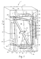
- a steam sterilization apparatus 1 includes a cabinet 10 which defines an interior chamber 12 .
- a rectangular door 14 opens and closes to allow items to be sterilized to be loaded and unloaded into the chamber through an opening 16 in the chamber.
- the door is sized to cover completely the opening and is preferably formed from a material which is resistant to the chemical environment within the chamber, such as a stainless steel plate.
- a closure assembly 20 selectively restrains the door.
- Hinges 22 pivotally connect a first vertical side or edge 24 of the door to a door frame, such as a frame or front wall 26 of the cabinet, which defines the opening.
- the hinges allow pivotal movement of the door during opening and closing.
- the hinges also permit a small amount of transverse motion of the door in a direction perpendicular to the front wall of the cabinet to allow a small door movement due to pressure changes within the sterilizer.
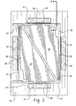
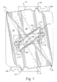
- the closure assembly 20 includes two generally triangular-shaped flat plates of substantially equal weight, namely an upper plate 28 and a lower plate 30 , which are pivotally mounted to a flat exterior face 32 of the door, and a coupling member 33 for articulating the plates from a disengaged position, in which the door 14 can be opened, to an engaged position, in which the door is restrained in position across the opening 16 .
- the plates 28 and 30 are formed from a rigid material, such as steel, and are of a sufficient thickness, e.g., 1 - 2 cm, to withstand the pressures exerted on the door from within the chamber 12 .
- Each of the plates has a generally right-angled corner 34 and 36 , respectively, which is indented, as will be described in further detail hereinafter.
- the two right-angled corners are positioned adjacent diagonally opposite corners 38 and 40 , respectively, of the door.
- the door first upper corner 38 is defined between the top of the door 41 and a second vertical side or edge 42 of the door that is furthest from the hinges and the first lower door corner 40 is defined between the bottom of the door 43 and the first vertical edge 24 of the door.
- the upper plate 28 is thus positioned with its right-angled corner 34 adjacent the first upper corner 38 of the door, and the lower plate is positioned with its right-angled corner 36 adjacent the first lower corner 40 of the door.
- the plates are arranged so that their longest sides 44 and 46, respectively, lie parallel to each other, in facing opposition and generally diagonally across the door.
- a gap 48 is preferably defined between the two plates.
- the plates are pivotally connected to the exterior face 32 of the door of the sterilizer at plate pivot points 50 and 52 , respectively, by any suitable pivoting means, such as a pivot pin.
- the pivot pins allow the plates to rotate in a plane parallel to the exterior face 32 of the door.
- the pivot points are located adjacent diagonally opposite corners of the door. Specifically, the pivot point 50 of the upper plate 28 is positioned adjacent a corner of the plate 53 closest to a second lower corner 54 of the door defined between the second edge 42 of the door and the bottom 43 of the door, while the pivot point 52 for the lower plate 30 is positioned adjacent a corner 55 of the plate which is adjacent a second upper corner 56 of the door, defined between the first edge 24 of the door and the top of the door 41 .
- FIGURE 1 shows the door hinges on the left edge of the door, the door could equally well be hinged on the right of the door, or on the top or bottom of the door, if desired.
- the plates 28 and 30 are shaped and positioned so that in the disengaged position the periphery of the plates does not extend beyond the periphery of the door.
- the horizontal and vertical edges of the two plates are not aligned in parallel with the adjacent vertical and horizontal edges of the door, but rather are offset by a few degrees, preferably from about 5-15°.
- the gap between a side edge 60 of the upper plate 28 and the adjacent second edge of the door 42 narrows from top to bottom of the door, while the gap between a side edge 62 of the lower plate 30 and the adjacent first edge 24 of the door widens from top to bottom of the door.
- the gap between an upper edge 64 of the upper plate 28 and the adjacent horizontal top 41 of the door narrows from the first edge 24 of the door to the second edge 42 of the door, while the gap between a bottom 68 of the lower plate 30 and the adjacent horizontal bottom 43 of the door widens from the first to the second edge.
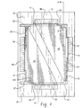
- FIGURE 4 which shows the plates in the engaged position
- the upper and lower and side edges of the two plates 64 , 68 , 60 and 66 define engagement portions.
- a first engagement portion 72 is defined by the upper edge 64 of the upper plate 28
- a second engagement portion 74 is defined by the lower edge 68 of the lower plate 30
- a third engagement portion 76 is defined by the side edge 60 of the upper plate
- a fourth engagement portion 78 is defined by the side edge 62 of the lower plate.
- each of the retaining bars 80, 82, 84, and 86 extends parallel to, and slightly spaced from, the adjacent edge of the door 41, 43, 42 and 44, respectively, so that the bars do not interfere with the opening and closing of the door.
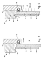
- Each of the retaining bars includes a spacer portion 90 which extends beyond the exterior face 32 of the door to a position which is slightly forward of the corresponding plate engagement portion 72 , 74 , 76 , and 78 . (See FIGURE 4.)
- a flange 92 extends perpendicularly from the forward end of the spacer portion.
- the flange on the bar 80 also extends parallel to the top 41 of the door, while the flanges on the bars 82 , 84 , and 86 also run parallel to their respective edges 43, 42 and 24 of the door.
- the flange overlaps the corresponding engagement portion when the closure assembly 20 is in the engaged position, as shown in FIGURE 5. Accordingly, each plate is engaged by two perpendicularly positioned flanges.
- a door seal such as a gasket 96
- a channel 98 which is defined in the front surface 26 of the cabinet and which extends around the perimeter of the opening 16.
- FIGURES 3 and 5 show the seal prior to activation.
- the channel is supplied with steam, or other pressurizing fluid while the plates 28 , 30 are in the engaged position.
- the seal moves outwardly from the channel, compressing the door 14 and the plate engagement portions 72 , 74 , 76 , and 78 against an interior sealing face 100 on the corresponding flange 92 , as shown in FIGURE 6.
- a leak-tight seal is thus formed between an interior surface 102 of the door and the front surface 26 of the cabinet, thus sealing the opening to the chamber 12 .
- the flanges 92 and engagement portions 72 , 74 , 76 , and 78 cooperate to prevent the door from opening in response to a pressure from within the chamber.
- the door is first pivoted from an open position, shown in FIGURE 1, to a closed position, shown in FIGURE 2, where the door is positioned generally parallel to the front surface 26 of the cabinet.
- the two plates 28 and 30 are rotated about their pivot points 50 and 52 , in a clockwise direction.
- the engagement portions 72 , 74 , 76 , and 78 of the plates are brought into engagement with the respective flanges 92 of the retainer bars 80 , 82 , 84 , and 86 .
- the plates are then in the positions shown in FIGURES 4 and 5.
- a cut-out portion 104 in the lower plate 30 is shaped to allow for the protrusion of the hinge 22.
- the upper plate 28 may be provided with a similar cut-out portion so that the plates may be operated on either a left opening or a right opening door. Additionally, it is desirable for the plates to be manufactured similarly so that they are of approximately equal or identical weight. Further, eliminating material along the top and bottom edges toward the corners can reduce the distance the plates move between the engaged and disengaged positions.
- each edge of the door is restrained from outward movement by the engagement of the corresponding engagement portion and flange. While it is also contemplated that a single engagement portion be provided on each of the plates 28 and 30 , rather than two engagement portions, the use of two engagement portions assists in restraining the door. Specifically, when an outward force is applied adjacent to a first engagement portion, the force will be distributed over the entire plate as the adjacent engagement portion resists pivoting of the plate around the first engagement portion.
- the coupling member 33 provides a convenient means for rotating the heavy plates with a minimum of rotational force.
- the coupling member preferably defines a flat rectangular plate, and may be formed from steel or other rigid material. It is pivotally connected at its center to the front face 32 of the door by an axle or shaft member 108 , such as a central pivot pin. Preferably, the axle member is located in the gap between the two plates, at the geometric center of the assembly.
- the axle member allows the coupling member to rotate in a plane parallel to the front face 32 of the door.
- Each of the plates 28, 30 may define a semi-circular cut-out portion 109 adjacent the central pivot pin 108 so that the plates do not obstruct rotation of the central pivot pin.
- a first, or upper portion 110 of the coupling member 33 overlaps the upper plate 28 while a second, or lower portion 112 of the coupling member overlaps the lower plate 30.
- First and second curved cam slots 114 and 116 are defined in the first and second portions 110 and 112, respectively.
- First and second low friction shafts or pins 118 and 120 are connected with the plates 28 and 30, respectively. The shafts extend outwardly from the plates and are received through the cam slots 114 and 116.
- the coupling member 33, the pivot pins 50 and 52, and the shafts 118 and 120 maintain the plates 28 and 30 in close proximity to the front face 32 of the door, particularly when the plates are in the disengaged position. other devices may also be added to maintain close proximity.
- the cam slots 114 and 116 are configured such that, in the disengaged position, the first shaft 118 is located adjacent a lower end of the first cam slot 114 while the second shaft 120 is at an upper end of the second cam slot 116.
- the positions of the shafts and the cam slots are reversed in the engaged position, with the first shaft 118 being cammed to the upper end of the first cam slot 114 and the second shaft 120 being cammed to the lower end of the second cam slot 116.
- the shafts optionally include an outer layer of a low friction material, such as a sleeve of TEFLON.
- the shafts include a rotatable outer portion, such as a sleeve, which is spaced from the shaft by bearings.
- the coupling member may be moved manually, by an operator, between the disengaged and engaged positions, or be power operated.
- a handle such as a wheel or crank, is connected to the coupling member 33 to rotate it between its two positions.
- the coupling member 33 rotates in a clockwise direction around the central pivot pin 108, and the two plates 28 and 30 are rotated clockwise around their respective pivot pins 50 and 52, into the engagement positions.
- the plates 28, 30 are mutually counterbalanced around the coupling member. Specifically, the upward force required to push the upper plate 28 into the engaged position is generally counterbalanced by the downward force of the lower plate 30 which tends to pull the lower plate to the engaged position.
- the two spacer plates 28 and 30 are bound to follow the cam slots 114 and 116 of the rotating coupling member 33.
- the net torque on the coupler should remain zero. Taking moments about the coupling member pivot point 108 , there are only two forces - the contact at the two cam surfaces. In order for them to equal zero, the cross product of the force and location vector for each contact is equal and opposite.
- the cam slots 114 and 116 are configured to cam the shafts smoothly such that when the plates 28 and 30 are in the engagement position, the plates 28 and 30 cannot be rotated by themselves to the disengaged position without rotating the coupling member 33 . This prevents inadvertent disengagement of the plates by any rotational force which may act on the plates.
- the engagement portions 72 and 74 of the plates 28 and 30 each define a camming surface 122 and 124, respectively, on a leading portion 126, 128, respectively, of the engagement portion.
- the camming surfaces are the first parts of the engagement portions to engage the corresponding retainer bars 80, and 82, respectively, when the plates are moved towards the engagement position.
- the camming surface slides against the inner surface 100 of the retaining bar flange, the plate is smoothly guided into closer proximity with the outer face 32 of the door so that the remainder of the engagement portion engages the flange 92 smoothly.
- the items are first loaded into the chamber 12 through the opening 16.
- the door 14 is then pivoted into a position where it covers the opening.
- the plates 28 and 30 are pivoted from the disengaged to the engaged position.
- the seal 96 is activated, pushing the engagement portions 72, 74, 76, and 78 into intimate engagement with the corresponding flanges 92 and sealing the interior surface of the door to the door frame 26.
- the chamber is evacuated by connecting a source of vacuum, such as a vacuum pump, to the chamber.
- a source of vacuum such as a vacuum pump
- the reduced pressure within the chamber tends to draw the door 14 towards the door frame 26.
- the spacer portions 90 provide the door with some freedom of movement, allowing the engagement portions to move inwardly and outwardly a small amount in response to the changing pressure within the chamber.
- the pressure within the chamber is returned to ambient pressure.
- the seal is deactivated by venting and/or evacuating the steam from within the seal and the plates 28, 30 are pivoted from the engaged to the disengaged position. The door is then opened and the sterilized or disinfected items removed.
- closure assembly 20 has been described with reference to a sterilizer door. It should be understood that the closure assembly is equally suited to selectively engaging a variety of doors across an opening to a chamber, in particular, doors which are subjected to high pressures from within the chamber.
Landscapes
- Health & Medical Sciences (AREA)
- Epidemiology (AREA)
- Life Sciences & Earth Sciences (AREA)
- Animal Behavior & Ethology (AREA)
- General Health & Medical Sciences (AREA)
- Public Health (AREA)
- Veterinary Medicine (AREA)
- Apparatus For Disinfection Or Sterilisation (AREA)
- Hinges (AREA)
- Wing Frames And Configurations (AREA)
- Chemical And Physical Treatments For Wood And The Like (AREA)
Claims (20)
- Appareil de stérilisation à vapeur (1) comprenant une chambre de pression (12), un cadre de porte (26) qui définit une ouverture (16) dans la chambre, une porte raccordée au cadre de porte, la porte étant dimensionnée pour couvrir l'ouverture, et un ensemble de fermeture (20) qui maintient sélectivement la porte dans une relation de proximité par rapport au cadre, l'appareil étant caractérisé par :une pluralité de brides (80, 82, 84, 86) raccordées au cadre de porte, au moins une bride étant adjacente à chacun de deux rebords opposés (41, 43, 24, 42) de la porte ; et,l'ensemble de fermeture comprenant :une première plaque (30), une partie supérieure (55, 34) de celle-ci étant raccordée de manière pivotante à la porte, la première plaque définissant au moins une première partie d'engagement (74, 78) qui pivote pour s'engager dans et de désengager d'une première des brides (82, 86) ;une deuxième plaque (28), une partie inférieure (53) de celle-ci étant raccordée de manière pivotante à la porte, la deuxième plaque définissant au moins une première partie d'engagement (72, 76) qui pivote pour s'engager dans et se désengager d'une seconde des brides (80, 84) ; et,un élément d'accouplement (33) qui couple la première plaque (30) à la deuxième plaque (28), les plaques (28, 30) ayant essentiellement la même masse et la même géométrie générale de telle sorte que les forces gravitationnelles sur les première et deuxième plaques soient contrebalancées autour de l'élément d'accouplement.
- Appareil selon la revendication 1, caractérisé en ce que :l'élément d'accouplement fait pivoter sélectivement les première et deuxième plaques entre une position désengagée, dans laquelle les parties d'engagement (74, 78, 72, 76) sont déplacées à l'écart des brides (80, 82, 84, 86) et une position d'engagement, dans laquelle les parties d'engagement s'engagent dans les brides.
- Appareil selon la revendication 2, caractérisé en outre par :un canal (98) défini dans le cadre de porte (26) autour de l'ouverture (16) ; et,un élément d'étanchéité (96) reçu dans le canal, l'élément d'étanchéité s'engageant sélectivement de manière étanche dans une surface intérieure (102) de la porte lorsque la porte (14) est dans la position d'engagement.
- Appareil selon l'une quelconque des revendications 1 à 3, caractérisé en ce que :l'élément d'accouplement (33) définit une première fente arquée (116) et une deuxième fente arquée (114) ;une première tige suiveuse (120) étant raccordée à une première extrémité à une surface externe de la première plaque (30) et s'étendant dans la première fente ; et,une deuxième tige suiveuse (118) étant raccordée à une première extrémité à une surface externe de la seconde plaque (28) et s'étendant dans la deuxième fente ;moyennant quoi les plaques tournent ensemble dans et hors de la position d'engagement lorsque l'élément d'accouplement tourne.
- Appareil selon la revendication 4, caractérisé en ce que :les plaques (28, 30) sont globalement triangulaires.
- Appareil selon l'une quelconque des revendications 1 à 5, caractérisé en ce que :la première plaque (30) définit un bord périphérique en forme de L (66, 68) et la deuxième plaque (28) définit un bord périphérique en forme de L (60, 64), un montant plus long (66) du bord en forme de L de la première plaque étant positionné à l'opposé d'un montant plus long (60) du flanc en forme de L de la deuxième plaque et un montant plus court (68) du bord périphérique en forme de L de la première plaque étant positionné à l'opposé d'un montant plus court (64) du bord en forme de L de la deuxième plaque, les premières parties d'engagement (72, 74, 76, 78) des première et deuxième plaques étant définies le long d'un des montants opposés plus longs et plus courts.
- Appareil selon la revendication 6, caractérisé en ce que :les montants plus longs (76, 78) et plus courts (72, 74) de chaque plaque (28, 30) sont définis à angles droits les uns par rapport aux autres ;les parties d'engagement (72, 74, 76, 78) sont définies à la fois le long des montants plus longs et plus courts ; et,les brides (80, 82, 84, 86) sont disposées le long des quatre rebords (24, 41, 42, 43) de la porte (14).
- Appareil selon l'une quelconque des revendications précédentes 6 et 7, caractérisé en ce que :la première plaque (30) est raccordée de manière pivotante à proximité d'une extrémité (55) du montant plus long (66) éloignée du montant plus court (68) ; et,la deuxième plaque (28) étant raccordée de manière pivotante à proximité d'une extrémité (53) du montant plus long (60) éloignée du montant plus court (68) .
- Appareil selon l'une quelconque des revendications 1 à 3 et 5 à 8, caractérisé par :un élément d'accouplement (33) pour faire pivoter de manière coordonnée les première et deuxième plaques (28, 30), l'élément d'accouplement comprenant :une première surface de came arquée (116) qui engage une tige suiveuse (120) sur la première plaque (30) ,une deuxième surface de came arquée (114) qui engage dans une tige suiveuse (118) sur la deuxième plaque ; et,un support rotatif (108) pour l'élément d'accouplement tel que : - lorsque l'élément d'accouplement tourne dans une direction, les surfaces de came (116, 114) écartent les tiges suiveuses (120, 118), déplaçant les parties d'engagement (72, 74, 76, 78) pour les engager dans les brides (80, 82, 84, 86) ; et, - lorsque l'élément d'accouplement tourne dans une direction opposée, les surfaces de came rapprochent les tiges suiveuses l'une vers l'autre, déplaçant les parties d'engagement pour les désengager des brides.
- Appareil selon la revendication 9, caractérisé en ce que :les surfaces de came (116, 114) ont une géométrie qui empêche les parties d'engagement (72, 74, 76, 78) d'être déplacées hors de leur engagement avec les brides (80, 82, 84, 86), à moins de faire tourner l'élément d' accouplement (33) .
- Ensemble de fermeture (20) destiné à maintenir sélectivement une porte (14) en engagement étanche autour d'une ouverture (16) dans une armoire (10), l'ensemble étant caractérisé par :des brides (80, 82, 84, 86) s'étendant depuis une face avant (26) de l'armoire ;une première plaque (30) qui comprend un premier point de pivotement (52) pour raccorder de manière pivotante la première plaque à une surface extérieure de la porte adjacente à un premier rebord (24) de la porte, la première plaque (30) définissant une première partie d'engagement (74) pour engager sélectivement une première des brides (82) et une deuxième partie d'engagement (78) pour engager sélectivement une deuxième des brides (86) ;une deuxième plaque (28) qui comprend un deuxième point de pivotement (50) pour raccorder de manière pivotante la deuxième plaque à la surface extérieure de la porte adjacente à un deuxième rebord (42) de la porte, la deuxième plaque (28) définissant une troisième partie d'engagement (72) pour engager sélectivement une troisième des brides (80) et une quatrième partie d'engagement (76) pour engager sélectivement une quatrième des brides (84) ; et,un élément d'accouplement (33) qui accouple la première plaque à la deuxième plaque pour faire tourner sélectivement les première et deuxième plaques depuis une position désengagée, dans laquelle les parties d'engagement sont déplacées à l'écart des brides, vers une position d'engagement, dans laquelle les parties d'engagement engagent les brides, les plaques (28, 30) ayant essentiellement la même masse et la même géométrie générale de telle sorte que les forces gravitationnelles sur les première et deuxième plaques soient contrebalancées autour de l'élément d'accouplement.
- Ensemble de fermeture selon la revendication 11, caractérisé en ce que :les première et deuxième plaques (30, 28) définissent globalement des triangles, les côtés les plus longs (46, 44) des triangles étant positionnés en vis-à-vis.
- Ensemble de fermeture selon la revendication 12, caractérisé en ce que :les première et deuxième parties d'engagement (74, 78) sont définies à angles droits l'une par rapport à l'autre et les troisième et quatrième parties d'engagement (72, 76) sont définies à angles droits l'une part rapport à l'autre.
- Ensemble de fermeture selon l'une quelconque des revendications 11 à 13, caractérisé en ce que :les points de pivotement (52, 50) sont positionnés pour raccorder de manière pivotante les première et deuxième plaques (30, 28) à proximité des coins diagonalement opposés (56, 54) de la face avant de la porte.
- Ensemble de fermeture selon l'une quelconque des revendications 12 à 14, caractérisé en ce que :la première partie d'engagement (74) a une position plus éloignée du premier point de pivotement (52) que la deuxième partie d'engagement (78) ;la première partie d'engagement comprend une surface de came (124) pour se déplacer contre la première bride (82) ;la troisième partie d'engagement (72) a une position plus éloignée du deuxième point de pivotement (50) que la quatrième partie d'engagement (76) ; et,la troisième partie d'engagement comprend une surface de came (122) pour se déplacer contre la troisième bride (80) .
- Ensemble de fermeture selon l'une quelconque des revendications 11 à 15, caractérisé en ce que :l'élément d'accouplement (33) définit une première fente (116) et une deuxième fente (114) ;un premier arbre (120) étant raccordé par une première extrémité à une surface externe de la première plaque et s'étendant dans la première fente ;un deuxième arbre (118) étant raccordé par une première extrémité à une surface externe de la deuxième plaque et s'étendant dans la deuxième fente ;moyennant quoi, en appliquant une force de rotation sur l'élément d'accouplement, les plaques (30, 28) pivotent dans et hors de leur position d'engagement.
- Procédé de retenue sélective d'une porte (14) à travers une ouverture (16), le procédé étant caractérisé par :un pivotement d'une première plaque (28) qui définit une première partie d'engagement (72) et une deuxième partie d'engagement (76) jusqu'à ce que la première partie d'engagement s'engage dans une première bride (80) adjacente à un premier rebord de la porte et jusqu'à ce que la deuxième partie d'engagement s'engage dans une deuxième bride (84) adjacente à un deuxième rebord de la porte, la première plaque étant raccordée de manière pivotante à la porte ;un pivotement d'une deuxième plaque (30) qui définit une troisième partie d'engagement (74) et une quatrième partie d'engagement (78) jusqu'à ce que la troisième partie d'engagement s'engage dans une troisième bride (82) adjacente à un troisième rebord de la porte et jusqu'à ce que la quatrième partie d'engagement s'engage dans une quatrième bride (86) adjacente à un quatrième rebord de la porte, la deuxième plaque étant raccordée de manière pivotante à la porte, les plaques (28, 30) ayant essentiellement la même masse et la même géométrie générale de telle sorte que les forces gravitationnelles sur les première et deuxième plaques soient contrebalancées.
- Procédé selon la revendication 17, caractérisé en outre par :une activation d'un joint (96) autour de l'ouverture (16) pour rendre étanche un espace entre l'ouverture et la porte.
- Procédé selon l'une quelconque des revendications 17 et 18, caractérisé en ce que :les étapes consistant à faire pivoter la première plaque (28) et à faire pivoter la deuxième plaque (30), comprennent :le pivotement de la première plaque (28) autour d'un coin inférieur (54) de la porte et de la deuxième plaque (30) autour d'un coin supérieur opposé (56) de la porte ; et,l'accouplement des première et deuxième plaques de telle sorte que les plaques pivotent de manière coordonnée, de telle sorte que, lorsque les plaques pivotent vers une position d'engagement, les forces gravitationnelles sur les deux plaques (28, 30) se contrebalancent.
- Procédé selon l'une quelconque des revendications 17 à 19, caractérisé en outre par :une application d'une pression de vide sur l'intérieur (12) de la porte (14) ; etune application d'une pression de vapeur sur une surface intérieure (102) de la porte, les brides (80, 82, 84, 86) coopérant pour maintenir la porte dans une relation d'étanchéité autour de l'ouverture (16).
Applications Claiming Priority (3)
| Application Number | Priority Date | Filing Date | Title |
|---|---|---|---|
| US09/257,117 US6319479B1 (en) | 1999-02-25 | 1999-02-25 | Closure for a hinged sterilizer door |
| US257117 | 1999-02-25 | ||
| PCT/US2000/005046 WO2000050716A1 (fr) | 1999-02-25 | 2000-02-24 | Systeme de fermeture d'une porte a charnieres pour sterilisateur |
Publications (2)
| Publication Number | Publication Date |
|---|---|
| EP1155210A1 EP1155210A1 (fr) | 2001-11-21 |
| EP1155210B1 true EP1155210B1 (fr) | 2003-12-17 |
Family
ID=22974961
Family Applications (1)
| Application Number | Title | Priority Date | Filing Date |
|---|---|---|---|
| EP00915904A Expired - Lifetime EP1155210B1 (fr) | 1999-02-25 | 2000-02-24 | Systeme de fermeture d'une porte a charnieres pour sterilisateur |
Country Status (7)
| Country | Link |
|---|---|
| US (1) | US6319479B1 (fr) |
| EP (1) | EP1155210B1 (fr) |
| AT (1) | ATE256808T1 (fr) |
| DE (1) | DE60007283T2 (fr) |
| DK (1) | DK1155210T3 (fr) |
| ES (1) | ES2212996T3 (fr) |
| WO (1) | WO2000050716A1 (fr) |
Families Citing this family (20)
| Publication number | Priority date | Publication date | Assignee | Title |
|---|---|---|---|---|
| US7121042B2 (en) * | 2002-11-15 | 2006-10-17 | Steris Inc. | Door assembly for sealing a chamber |
| US7387076B2 (en) * | 2005-04-08 | 2008-06-17 | Merritt Industies, Inc. | Locking system for a door of an enclosure |
| US8236253B2 (en) | 2007-04-30 | 2012-08-07 | Midmark Corporation | Portable sterilizing apparatus for surgical and dental instruments |
| USD603053S1 (en) | 2008-04-30 | 2009-10-27 | Midmark Corporation | Portable sterilizing apparatus |
| USD598564S1 (en) | 2008-04-30 | 2009-08-18 | Midmark Corporation | Handle for portable sterilizing apparatus |
| USD598565S1 (en) | 2008-04-30 | 2009-08-18 | Midmark Corporation | External condensation tank for a sterilizer |
| US8206660B2 (en) * | 2009-03-30 | 2012-06-26 | American Sterilizer Company | Door seal system for steam sterilizer |
| US8454901B1 (en) * | 2009-05-06 | 2013-06-04 | Clarence J. Snyder, III | Mobile apparatus and method to sterilize surgical trays |
| JP2011078354A (ja) * | 2009-10-07 | 2011-04-21 | My Foods Kk | 食品殺菌方法、及び食品殺菌装置 |
| US9616143B2 (en) | 2013-07-17 | 2017-04-11 | Progressive Sterilization, Llc | Mobile apparatus and method for sterilizing one or more surgical trays with integrable transfer and storage system |
| CN104871809B (zh) * | 2014-02-28 | 2018-05-08 | 陕西森盛菌业科技有限公司 | 食用菌菌种灭菌箱 |
| EP3116810A4 (fr) | 2014-03-10 | 2018-03-28 | Pmbs, Llc | Appareil de stérilisation mobile, et procédé d'utilisation correspondant |
| US9439992B2 (en) | 2014-03-10 | 2016-09-13 | Promedica, Inc. | Autoclave sterilization cabinet |
| US10086100B1 (en) | 2017-07-28 | 2018-10-02 | Pmbs, Llc | Mobile sterilization apparatus and method for using the same |
| TWI862479B (zh) * | 2018-07-31 | 2024-11-21 | 荷蘭商荷蘭Tno自然科學組織公司 | 用於海洋船隻的抗爆內膜門 |
| US11408213B2 (en) | 2020-07-17 | 2022-08-09 | Focus-On Tools | Locking system for a secure safe |
| CN111946217A (zh) * | 2020-08-26 | 2020-11-17 | 杨永根 | 一种实木门 |
| CN113893373B (zh) * | 2021-10-11 | 2023-04-07 | 湖北工业大学 | 一种用于推拉门窗的消毒装置 |
| CN115045592B (zh) * | 2022-06-07 | 2024-05-14 | 成都蓝峰科技有限公司 | 用于过氧化氢低温等离子体灭菌器的舱门 |
| USD1065537S1 (en) | 2024-07-30 | 2025-03-04 | Stericube Surgical Systems, Llc | Filter separator |
Family Cites Families (9)
| Publication number | Priority date | Publication date | Assignee | Title |
|---|---|---|---|---|
| US4261189A (en) * | 1979-01-22 | 1981-04-14 | Square D Company | Panelboard vent assembly |
| US4387740A (en) * | 1981-05-15 | 1983-06-14 | T. D. Williamson, Inc. | Cam-flange |
| US4607760A (en) * | 1985-07-25 | 1986-08-26 | Roche John N | Closure for a pressurized chamber |
| US4756123A (en) | 1986-11-25 | 1988-07-12 | American Sterilizer Company | Chamber door |
| US5148938A (en) * | 1987-03-04 | 1992-09-22 | Morgan Jr Howard W | Pressure vessel |
| GB8809516D0 (en) | 1988-04-22 | 1988-05-25 | Plenty Ltd | Improved closure for pipe/vessel |
| US4891910A (en) | 1988-12-30 | 1990-01-09 | American Sterilizer Company | Apparatus for sealing a door |
| US4999165A (en) * | 1989-10-27 | 1991-03-12 | Mdt Corporation | Pressure vessel with improved gasket valve |
| US5711450A (en) | 1996-03-15 | 1998-01-27 | Reneau; Raymond Paul | Door for closing an opening in a pressure vessel |
-
1999
- 1999-02-25 US US09/257,117 patent/US6319479B1/en not_active Expired - Lifetime
-
2000
- 2000-02-24 EP EP00915904A patent/EP1155210B1/fr not_active Expired - Lifetime
- 2000-02-24 WO PCT/US2000/005046 patent/WO2000050716A1/fr not_active Ceased
- 2000-02-24 DK DK00915904T patent/DK1155210T3/da active
- 2000-02-24 AT AT00915904T patent/ATE256808T1/de not_active IP Right Cessation
- 2000-02-24 DE DE60007283T patent/DE60007283T2/de not_active Expired - Lifetime
- 2000-02-24 ES ES00915904T patent/ES2212996T3/es not_active Expired - Lifetime
Also Published As
| Publication number | Publication date |
|---|---|
| US6319479B1 (en) | 2001-11-20 |
| DK1155210T3 (da) | 2004-04-26 |
| WO2000050716A1 (fr) | 2000-08-31 |
| ES2212996T3 (es) | 2004-08-16 |
| DE60007283D1 (de) | 2004-01-29 |
| DE60007283T2 (de) | 2004-09-23 |
| ATE256808T1 (de) | 2004-01-15 |
| EP1155210A1 (fr) | 2001-11-21 |
Similar Documents
| Publication | Publication Date | Title |
|---|---|---|
| EP1155210B1 (fr) | Systeme de fermeture d'une porte a charnieres pour sterilisateur | |
| EP0730907B1 (fr) | Système de transfert à travers une ouverture | |
| US6416144B1 (en) | Sterilizer horizontal motorized sliding door closure | |
| AU2002320541B2 (en) | Panel seal for an air handling unit | |
| US11883815B2 (en) | Apparatus for sterile transfer of material between a container and an isolator | |
| JP3672704B2 (ja) | 搬送用のポートシステム | |
| AU2002320541A1 (en) | Panel seal for an air handling unit | |
| CN105518804B (zh) | 提供两个封闭空间的流体密封连接的包括在连接之前进行保持的构件的装置 | |
| US9168520B2 (en) | Chamber for sealed junction device and aseptic transfer device | |
| US20040042943A1 (en) | Compact sterilising or disinfection apparatus | |
| US6017105A (en) | Horizontal sliding door guidance method | |
| JP7650520B2 (ja) | 2つの封入容積間の密封移送を可能にするドアアセンブリ | |
| CN113891788B (zh) | 具有更高安全性的两个密闭空间之间的密封连接装置 | |
| US4607760A (en) | Closure for a pressurized chamber | |
| US5295605A (en) | Shutter device for pressure container | |
| JP4897705B2 (ja) | ディスプレーユニットのダブル運動式開閉システム | |
| US20250332584A1 (en) | Door arrangement fitted to a first enclosed space for reducing contamination risks when a second enclosed space is connected to the first enclosed space | |
| US8511509B2 (en) | Storage enclosures | |
| JP7689381B2 (ja) | 2つの回転軸を有する移送シュートを備えるドア構造 | |
| US5037147A (en) | Latching mechanism for chamber access door | |
| US6264901B1 (en) | Space frame sterilizer door | |
| JPH09327381A (ja) | 圧力ロック組立体及び圧力容器 | |
| JP3385969B2 (ja) | 密閉容器 | |
| JP2810406B2 (ja) | 圧力容器の扉装置 | |
| JP3313239B2 (ja) | コンテナの蓋開閉装置 |
Legal Events
| Date | Code | Title | Description |
|---|---|---|---|
| PUAI | Public reference made under article 153(3) epc to a published international application that has entered the european phase |
Free format text: ORIGINAL CODE: 0009012 |
|
| 17P | Request for examination filed |
Effective date: 20010825 |
|
| AK | Designated contracting states |
Kind code of ref document: A1 Designated state(s): AT BE CH CY DE DK ES FI FR GB GR IE IT LI LU MC NL PT SE |
|
| RIN1 | Information on inventor provided before grant (corrected) |
Inventor name: HOUSTON, JOHN, C. |
|
| GRAP | Despatch of communication of intention to grant a patent |
Free format text: ORIGINAL CODE: EPIDOSNIGR1 |
|
| GRAS | Grant fee paid |
Free format text: ORIGINAL CODE: EPIDOSNIGR3 |
|
| GRAA | (expected) grant |
Free format text: ORIGINAL CODE: 0009210 |
|
| AK | Designated contracting states |
Kind code of ref document: B1 Designated state(s): AT BE CH CY DE DK ES FI FR GB GR IE IT LI LU MC NL PT SE |
|
| PG25 | Lapsed in a contracting state [announced via postgrant information from national office to epo] |
Ref country code: CY Free format text: LAPSE BECAUSE OF FAILURE TO SUBMIT A TRANSLATION OF THE DESCRIPTION OR TO PAY THE FEE WITHIN THE PRESCRIBED TIME-LIMIT Effective date: 20031217 Ref country code: AT Free format text: LAPSE BECAUSE OF FAILURE TO SUBMIT A TRANSLATION OF THE DESCRIPTION OR TO PAY THE FEE WITHIN THE PRESCRIBED TIME-LIMIT Effective date: 20031217 Ref country code: NL Free format text: LAPSE BECAUSE OF FAILURE TO SUBMIT A TRANSLATION OF THE DESCRIPTION OR TO PAY THE FEE WITHIN THE PRESCRIBED TIME-LIMIT Effective date: 20031217 |
|
| REG | Reference to a national code |
Ref country code: GB Ref legal event code: FG4D |
|
| REG | Reference to a national code |
Ref country code: CH Ref legal event code: EP |
|
| REG | Reference to a national code |
Ref country code: IE Ref legal event code: FG4D |
|
| REF | Corresponds to: |
Ref document number: 60007283 Country of ref document: DE Date of ref document: 20040129 Kind code of ref document: P |
|
| PG25 | Lapsed in a contracting state [announced via postgrant information from national office to epo] |
Ref country code: LU Free format text: LAPSE BECAUSE OF NON-PAYMENT OF DUE FEES Effective date: 20040224 |
|
| PG25 | Lapsed in a contracting state [announced via postgrant information from national office to epo] |
Ref country code: MC Free format text: LAPSE BECAUSE OF NON-PAYMENT OF DUE FEES Effective date: 20040228 |
|
| PG25 | Lapsed in a contracting state [announced via postgrant information from national office to epo] |
Ref country code: GR Free format text: LAPSE BECAUSE OF FAILURE TO SUBMIT A TRANSLATION OF THE DESCRIPTION OR TO PAY THE FEE WITHIN THE PRESCRIBED TIME-LIMIT Effective date: 20040317 |
|
| PG25 | Lapsed in a contracting state [announced via postgrant information from national office to epo] |
Ref country code: DK Free format text: LAPSE BECAUSE OF NON-PAYMENT OF DUE FEES Effective date: 20040331 |
|
| REG | Reference to a national code |
Ref country code: SE Ref legal event code: TRGR |
|
| REG | Reference to a national code |
Ref country code: DK Ref legal event code: T3 |
|
| REG | Reference to a national code |
Ref country code: CH Ref legal event code: NV Representative=s name: TROESCH SCHEIDEGGER WERNER AG |
|
| NLV1 | Nl: lapsed or annulled due to failure to fulfill the requirements of art. 29p and 29m of the patents act | ||
| REG | Reference to a national code |
Ref country code: ES Ref legal event code: FG2A Ref document number: 2212996 Country of ref document: ES Kind code of ref document: T3 |
|
| ET | Fr: translation filed | ||
| PLBE | No opposition filed within time limit |
Free format text: ORIGINAL CODE: 0009261 |
|
| STAA | Information on the status of an ep patent application or granted ep patent |
Free format text: STATUS: NO OPPOSITION FILED WITHIN TIME LIMIT |
|
| 26N | No opposition filed |
Effective date: 20040920 |
|
| PG25 | Lapsed in a contracting state [announced via postgrant information from national office to epo] |
Ref country code: PT Free format text: LAPSE BECAUSE OF NON-PAYMENT OF DUE FEES Effective date: 20040517 |
|
| PGFP | Annual fee paid to national office [announced via postgrant information from national office to epo] |
Ref country code: CH Payment date: 20080228 Year of fee payment: 9 |
|
| PGFP | Annual fee paid to national office [announced via postgrant information from national office to epo] |
Ref country code: FI Payment date: 20080228 Year of fee payment: 9 Ref country code: IE Payment date: 20080227 Year of fee payment: 9 Ref country code: SE Payment date: 20080227 Year of fee payment: 9 |
|
| PGFP | Annual fee paid to national office [announced via postgrant information from national office to epo] |
Ref country code: BE Payment date: 20080306 Year of fee payment: 9 |
|
| BERE | Be: lapsed |
Owner name: *STERIS CORP. Effective date: 20090228 |
|
| REG | Reference to a national code |
Ref country code: CH Ref legal event code: PL |
|
| EUG | Se: european patent has lapsed | ||
| PG25 | Lapsed in a contracting state [announced via postgrant information from national office to epo] |
Ref country code: LI Free format text: LAPSE BECAUSE OF NON-PAYMENT OF DUE FEES Effective date: 20090228 Ref country code: CH Free format text: LAPSE BECAUSE OF NON-PAYMENT OF DUE FEES Effective date: 20090228 Ref country code: FI Free format text: LAPSE BECAUSE OF NON-PAYMENT OF DUE FEES Effective date: 20090224 |
|
| REG | Reference to a national code |
Ref country code: IE Ref legal event code: MM4A |
|
| PG25 | Lapsed in a contracting state [announced via postgrant information from national office to epo] |
Ref country code: IE Free format text: LAPSE BECAUSE OF NON-PAYMENT OF DUE FEES Effective date: 20090224 |
|
| PG25 | Lapsed in a contracting state [announced via postgrant information from national office to epo] |
Ref country code: BE Free format text: LAPSE BECAUSE OF NON-PAYMENT OF DUE FEES Effective date: 20090228 |
|
| PG25 | Lapsed in a contracting state [announced via postgrant information from national office to epo] |
Ref country code: SE Free format text: LAPSE BECAUSE OF NON-PAYMENT OF DUE FEES Effective date: 20090225 |
|
| PGFP | Annual fee paid to national office [announced via postgrant information from national office to epo] |
Ref country code: IT Payment date: 20120224 Year of fee payment: 13 |
|
| REG | Reference to a national code |
Ref country code: DE Ref legal event code: R082 Ref document number: 60007283 Country of ref document: DE Representative=s name: VON KREISLER SELTING WERNER, DE Ref country code: DE Ref legal event code: R082 Ref document number: 60007283 Country of ref document: DE Representative=s name: VON KREISLER SELTING WERNER - PARTNERSCHAFT VO, DE |
|
| REG | Reference to a national code |
Ref country code: DE Ref legal event code: R082 Ref document number: 60007283 Country of ref document: DE Representative=s name: VON KREISLER SELTING WERNER - PARTNERSCHAFT VO, DE |
|
| PGFP | Annual fee paid to national office [announced via postgrant information from national office to epo] |
Ref country code: ES Payment date: 20130226 Year of fee payment: 14 Ref country code: FR Payment date: 20130311 Year of fee payment: 14 Ref country code: GB Payment date: 20130227 Year of fee payment: 14 Ref country code: DE Payment date: 20130227 Year of fee payment: 14 |
|
| REG | Reference to a national code |
Ref country code: DE Ref legal event code: R119 Ref document number: 60007283 Country of ref document: DE |
|
| GBPC | Gb: european patent ceased through non-payment of renewal fee |
Effective date: 20140224 |
|
| REG | Reference to a national code |
Ref country code: FR Ref legal event code: ST Effective date: 20141031 |
|
| REG | Reference to a national code |
Ref country code: DE Ref legal event code: R119 Ref document number: 60007283 Country of ref document: DE Effective date: 20140902 |
|
| PG25 | Lapsed in a contracting state [announced via postgrant information from national office to epo] |
Ref country code: DE Free format text: LAPSE BECAUSE OF NON-PAYMENT OF DUE FEES Effective date: 20140902 Ref country code: GB Free format text: LAPSE BECAUSE OF NON-PAYMENT OF DUE FEES Effective date: 20140224 Ref country code: FR Free format text: LAPSE BECAUSE OF NON-PAYMENT OF DUE FEES Effective date: 20140228 |
|
| REG | Reference to a national code |
Ref country code: ES Ref legal event code: FD2A Effective date: 20150330 |
|
| PG25 | Lapsed in a contracting state [announced via postgrant information from national office to epo] |
Ref country code: ES Free format text: LAPSE BECAUSE OF NON-PAYMENT OF DUE FEES Effective date: 20140225 |
|
| PG25 | Lapsed in a contracting state [announced via postgrant information from national office to epo] |
Ref country code: IT Free format text: LAPSE BECAUSE OF NON-PAYMENT OF DUE FEES Effective date: 20140224 |