EP1155826A2 - Machine rotative d'impression - Google Patents
Machine rotative d'impression Download PDFInfo
- Publication number
- EP1155826A2 EP1155826A2 EP01116647A EP01116647A EP1155826A2 EP 1155826 A2 EP1155826 A2 EP 1155826A2 EP 01116647 A EP01116647 A EP 01116647A EP 01116647 A EP01116647 A EP 01116647A EP 1155826 A2 EP1155826 A2 EP 1155826A2
- Authority
- EP
- European Patent Office
- Prior art keywords
- cylinder
- rotary printing
- printing machine
- cylinders
- machine according
- Prior art date
- Legal status (The legal status is an assumption and is not a legal conclusion. Google has not performed a legal analysis and makes no representation as to the accuracy of the status listed.)
- Granted
Links
Images


Classifications
-
- B—PERFORMING OPERATIONS; TRANSPORTING
- B41—PRINTING; LINING MACHINES; TYPEWRITERS; STAMPS
- B41F—PRINTING MACHINES OR PRESSES
- B41F13/00—Common details of rotary presses or machines
- B41F13/008—Mechanical features of drives, e.g. gears, clutches
-
- B—PERFORMING OPERATIONS; TRANSPORTING
- B41—PRINTING; LINING MACHINES; TYPEWRITERS; STAMPS
- B41F—PRINTING MACHINES OR PRESSES
- B41F13/00—Common details of rotary presses or machines
- B41F13/004—Electric or hydraulic features of drives
- B41F13/0045—Electric driving devices
-
- B—PERFORMING OPERATIONS; TRANSPORTING
- B41—PRINTING; LINING MACHINES; TYPEWRITERS; STAMPS
- B41P—INDEXING SCHEME RELATING TO PRINTING, LINING MACHINES, TYPEWRITERS, AND TO STAMPS
- B41P2213/00—Arrangements for actuating or driving printing presses; Auxiliary devices or processes
- B41P2213/70—Driving devices associated with particular installations or situations
- B41P2213/73—Driving devices for multicolour presses
- B41P2213/734—Driving devices for multicolour presses each printing unit being driven by its own electric motor, i.e. electric shaft
-
- B—PERFORMING OPERATIONS; TRANSPORTING
- B65—CONVEYING; PACKING; STORING; HANDLING THIN OR FILAMENTARY MATERIAL
- B65H—HANDLING THIN OR FILAMENTARY MATERIAL, e.g. SHEETS, WEBS, CABLES
- B65H2557/00—Means for control not provided for in groups B65H2551/00 - B65H2555/00
- B65H2557/20—Calculating means; Controlling methods
- B65H2557/264—Calculating means; Controlling methods with key characteristics based on closed loop control
- B65H2557/2644—Calculating means; Controlling methods with key characteristics based on closed loop control characterised by PID control
Definitions
- the present invention relates to the combination of cylinders Rotary printing machine for individual cylinder groups and a drive control therefor.
- a printing press From DE 38 28 638 C1 a printing press is known, its cylinders and rollers are driven by a main motor via a toothed belt.
- the engine will regulated on the basis of actual values tapped on the load side.
- the cylinders and rollers of the Printing presses are coupled to one another via a drive wheel train. Through the described regulation, vibrations in the drive wheel train are difficult or keep low with great technical effort. Because the load moment of inertia is very large, this known regulation is slow and at most has a low one Control dynamics.
- DE 41 38 479 A1 proposes to drive the cylinders of the printing press by one electric motor each.
- a control system for such a printing press is included known individually driven cylinders.
- the pressure point groups are assigned to folders, from which they receive theirs Get position reference.
- the proposed control system essentially consists of a fast BUS system for the individual drives and the drive controllers Pressure point group and a superordinate control system for the administration of the Pressure point groups.
- a printing machine known from JP-A 63-236651 has printing units which are individually driven by their own drive motors.
- the printing units comprise mechanically coupled in pairs for their common drive Blanket cylinder and plate cylinder.
- the motors drive on each Plate cylinders of the printing units. From the plate cylinders is over Gear couplings driven on the blanket cylinders.
- the engines are sitting directly on the shafts of the plate cylinders. Regulators of the motors Machine control signals as setpoint signals and engine speed and Motor speed signals supplied as actual value signals. The regulation of the engines takes place depending on a comparison between the setpoint signals and the Actual value signals, i.e. based on the difference between the setpoint signals and the Actual value signals on the motor side.
- the present invention has set itself the task of being highly flexible create usable, yet economical rotary printing press.
- blanket cylinder and plate cylinder form one Rotary printing machine in pairs a cylinder group, in each case one Blanket cylinder and a plate cylinder are mechanically coupled and are driven together by a separate drive motor for each cylinder group.
- each with its own drive motors can be at a Rotary printing machine optimal in technical and economic terms Pressure points are formed.
- Pressure points in this context each understood the pairs of cylinders, between which a paper web to be printed runs through and is printed on one or both sides. Accordingly belong to one Pressure point formed according to the invention in each case one cylinder group and one corresponding impression cylinder, which may belong to the cylinder group, but not got to. In the latter case, one printing point is assigned to two by one Cylinder groups formed.
- the pressure points are Printing press mechanically independent in both cases, d. H. the pressure points the printing press are electrically coupled together.
- the Blanket cylinder driven, which in turn via the mechanical coupling on the Drives plate cylinders of the same cylinder group.
- the drive can also drive the plate cylinder shaft, so that the blanket cylinder only via the mechanical coupling of the plate cylinder is driven.
- the Blanket cylinders are decisive for the positional accuracy or Circumference register setting.
- the first solution has the advantage that the Cylinder that ultimately comes into direct contact with a paper web to be printed comes, not only via a transmission element that may be subject to play must be driven.
- One cylinder group is on one side of the pressure and two cylinder groups are on the one Opposite pressure side of a paper web running between them.
- the rubber cylinder preferably forms the one on the printing side of the paper web arranged cylinder group the impression cylinder for the other two Rubber cylinder arranged on the opposite printing side of the paper web Cylinder groups, both of which are advantageously operated alternately can.
- This configuration offers the greatest versatility for a rubber / rubber production, because with continuous production the two mutually rubber cylinder can be configured for a change in pressure can. This is done by changing the plate of a rubber cylinder that is not in use assigned plate cylinder.
- Each cylinder group can be stored in a single frame his.
- the two one printing side of the paper web are horizontal opposite groups of cylinders to a stored in a frame Cylinder unit summarized.
- a cylinder group can according to the invention around an impression cylinder for the Blanket cylinders are expanded.
- This third cylinder of the so formed Cylinder group can be mechanically coupled to the blanket cylinder, preferably by a further gear coupling.
- Such a cylinder group represents already represents a printing point, between the blanket and impression cylinder which too printing paper web is passed through.
- the impression cylinder can be a steel or can also be another blanket cylinder for double-sided printing.
- Such a An impression cylinder can in particular also be a central cylinder of a cylinder unit with, for example, nine or ten cylinders.
- too preferred embodiment of the invention is such a central cylinder of one own drive motor driven.
- This type of summary grants the maximum versatility for a cylinder unit.
- each of the Central cylinder assigned cylinder groups from blanket and plate cylinders can be reversed individually and independently of the other cylinder groups, like this for example for alternating pressure or for flying plate changes.
- the output from a drive motor takes place on the respective cylinder group preferably by means of a toothed belt.
- a toothed belt Possibility of high damping of a drive motor and the driven cylinders existing mechanical system of great value, as yet is explained.
- the invention also permits direct drive, which can even be advantageous for small cylinders.
- a toothed belt has the advantage of a backlash-free running and a not absolutely fixed gear ratio.
- gears for the mechanical coupling between the cylinders inside a group of cylinders preferably provided gears, although others Transmission links are also conceivable.
- the intermeshing Gears can be spur or helical. With helical gears for the side register adjustment the blanket cylinder is shifted lengthways while his drive and / or driven gears remain stationary according to the invention. Otherwise, with the side register would also be a circumferential register adjustment required. When using straight toothed gears the blanket cylinder along with its fixed gear or gears postponed.
- the inking roller or the inking rollers or dampening rollers of an inking unit or one Ink and dampening units that are assigned to a cylinder group can or can According to the invention mechanically coupled to this cylinder group, so that the Ink roller or the ink rollers from the drive motor of this cylinder group with are driven. With this solution, the technical control effort can be low being held.
- the mechanical coupling of the inking unit is in mind of the modular principle pursued by the invention is not quite as ideal as the stronger one preferred self-drive for the roller or the rollers of the inking unit. After this likewise preferred embodiment of the invention, each inking unit has one own drive motor for his ink rollers.
- Such a drive motor also drives preferably via a backlash-free toothed belt with high damping and if necessary via a reduction gear transmission, the inking roller or in the case several ink rollers on the plate cylinder of the corresponding cylinder group next lying ink roller.
- the peripheral speed of this ink roller advantageously adjustable, especially with negative slip compared to Plate cylinder, the peripheral speed of the ink roller preferably something is less than that of the corresponding plate cylinder.
- the position or speed of a cylinder are regulated known in which a mechanical encoder on the motor side for detecting the Motor speed or the rotor angular position of the motor for a target / actual comparison of the Motor control is used.
- this known regulation comes up with larger increasing inertia from the load to the motor to their dynamic limits. If the actual position is measured on the motor shaft, then lie both coupling and mechanical load outside the actual control loop. she can, however, react on the motor shaft Influence acceleration torques.
- the engine which in this case is an essential one This means that the mass is smaller than the coupling and the cylinder influenced.
- the load torque is heavily frequency-dependent, which ultimately determines the dynamic behavior of the system.
- a Setpoint changes are first tensioned to the springs that are closest to the motor are located.
- the engine torque caused by the controller accelerates parts of the Coupling and subsequently the cylinder or the driven roller.
- Energy is stored in the springs as well as in the mass movement at this time, whose division is constantly changing.
- the engine likes it within a short time have taken the correct position, but is due to the occurring mass forces distracted again, which leads to another control process.
- the system must go through controlled, stabilized a relatively slow controller.
- the present invention therefore also has the task of regulating to create, with the position and / or the speed of a rotary printing press a cylinder or a roller that is driven by a motor, performance-optimized and with sufficiently high control quality, d. H. in terms of dynamics and the speed or position accuracy can be controlled.
- the scheme is supposed to be inexpensive and not too high demands on the coupling of motor and Place the load, in particular on the torsional rigidity and freedom from play of the coupling.
- At least the drive motors are preferably on the same pressure side cylinder groups of a cylinder unit working in a paper web, position-controlled. So-called ideal position control is preferred, i.e. a delay free Position control with following error. On this, for technical reasons However, the desired, complex type of position control can also be dispensed with become. A simple position control is also a preferred, in particular cheaper, embodiment of the invention.
- the drive motor can even in the dual-mass oscillator according to the invention be careful.
- the load acting as a low pass filter is insensitive to the Vibrations of the much smaller motor.
- they can Effects of the load on the drive motor are neglected.
- the inventive, not least because of their simplicity cheap regulation offers the Another advantage that they are simply the wide range of Mass inertia between load and motor and on itself during operation changing parameters, such as the elasticity of a coupling, can be set can.
- the actual value transmitter figuratively speaking, moved from the motor side to the load side forms the main controlled variable for the controller of the motor, d. H. the engine is powered by the Load side guided by their actual value.
- the engine is powered by the Load side guided by their actual value.
- a particularly preferred Embodiment of the invention is not a mechanical actual value transmitter for the detection the position or the speed of the motor required for the regulation of the motor. Any actual value detection integrated in the motor can be advantageous for the pure one Drive monitoring, may be used for an engine emergency shutdown.
- the actual value transmitter for the control is according to the invention on torque-free shaft end of the driven cylinder of a cylinder group or attached roller of an inking unit.
- Electric asynchronous motors are particularly advantageous as the drive motors used. So far, an asynchronous motor has only been used when using a large motor had to drive a small load. For the present case, where a Drive motor drives a cylinder group or the rollers of an inking unit the driven load has a comparatively high mass moment of inertia compared to the drive motor, the use of asynchronous motors is not known. For the purposes of the regulation according to the invention instead of a load transmitter of a motor encoder, asynchronous motors are particularly suitable. Opposite to that for the have been used in the relevant applications DC motors Asynchronous motors have a higher field stiffness, so that their use is dynamic and Control quality of the system to be controlled improved. The use of others Motor types, for example DC motors, are not, however, fundamental locked out.
- the stability of the scheme is due to the preferred use of a backlash-free Toothed belt with high damping as a coupling between the motor and the load improved.
- the drive motor can even in the case of the dual-mass oscillator in question be careful.
- the load acting as a low pass filter is insensitive to the Vibrations of the much smaller motor. On the other hand, they can Effects of the load on the drive motor are neglected.
- a paper web 1 to be printed becomes between the two opposing blanket cylinders 2 two Cylinder groups 10 passed.
- the two cylinder groups 10 are each formed by the blanket cylinder 2 and an associated plate cylinder 3, the are mechanically coupled to each other for the common drive.
- the mechanical Coupling is shown schematically by a line between the center points of the two cylinders 2 and 3 indicated. 1 in the embodiment each of the blanket cylinders 2 of each cylinder group 10 by a three-phase motor 5 driven.
- the configuration according to FIG. 1, in each case only one Blanket cylinder 2 and a plate cylinder 3 by a mechanical coupling a cylinder group 10 are summarized, is characterized by its simple Construction and the highest possible degree of configuration freedom in the formation of Pressure points or pressure point groups.
- Fig. 2 shows a variant for the formation of a pressure point, in which an impression cylinder 4 mechanically coupled for the blanket cylinder 2 with this blanket cylinder 2 is.
- the cylinder group 10 is made up of the Blanket cylinder 2, its impression cylinder 4 and the plate cylinder 3 and their mechanical coupling together, so that the pressure point by a single Cylinder group 10 is formed.
- FIG. 2 is in contrast 1 of the blanket cylinder 2, but of this cylinder assigned plate cylinder 3 driven by a three-phase motor 5.
- the variant for combining cylinders into a cylinder group is hers constant delivery behavior due to the mechanical coupling of the blanket cylinder 2 with its impression cylinder 4 and that because of this mechanical coupling there is no direct interference between cylinders 2 and 4.
- the Impression cylinder 4 can be a second blanket cylinder or a steel cylinder, for example, a central cylinder of a nine or ten cylinder unit.
- the assignment of the motors 5 to the blanket cylinders 2 and the plate cylinders 3 can be interchanged in both exemplary embodiments.
- the drive of the Plate cylinder 3 has the advantage that the cylinder group 10 reversed more easily can be while in the other case when driving the blanket cylinder 2 on the paper web 1 directly printing cylinder is driven and thereby a drive free of playful transmission elements, such as gears, possible is.
- a cylinder unit 20 is shown, consisting of a central Steel cylinders 6 and four cylinder groups 10 assigned to this central cylinder 6.
- a blanket cylinder 2 and a plate cylinder 3 are in this Embodiment combined into a cylinder group 10.
- a separate three-phase motor 5 is provided for driving the Central cylinder 6, .
- the central cylinder 6 with one of the four cylinder groups 10 a cylinder group form according to the variant shown in Fig. 2. This would make your own Motor 5 for the central cylinder 6 can be saved.
- the in 3 shows a summary of the smallest possible cylinder groups 10 and self-propelled central cylinder 6 to a cylinder unit 20 the highest possible Flexibility in terms of configuration options.
- one is formed from pairs of cylinders Cylinder group 10 in terms of their configurability, a concept with each individually driven cylinders equal.
- the interaction is one of a pair of blankets / plate cylinders 2, 3 existing cylinder group 10 shown with an ink roller 7.
- the Ink roller 7 via its own drive by a motor 5, which to the motor 5 for the cylinder group 10 may be identical, but need not be.
- the engine 5 for the Ink roller 7 drives via a toothed belt 15 and a pair of gears 16, 17, which Gear 17 sits on the shaft of the ink roller 7, the ink roller 7.
- the different moments of inertia of the motor 5 and the inking roller 7 through a suitable choice of gear ratios for the output via the toothed belt 15 and the gear pair 16, 17 disarmed.
- the peripheral speed of the ink roller 7 is adjustable with a slightly negative Slip against the plate cylinder 3. This can counteract the danger be that the mechanical coupling formed by a pair of gears 12, 13 between the blanket cylinder 2 and the plate cylinder 3 from the meshing is lifted.
- the cylinder group 10 is driven by the engine 5 via the toothed belt 11 on the blanket cylinder 2.
- the mechanical coupling between the Blanket cylinder 2 and the plate cylinder 3 of the same cylinder group 10 form the two gears 12 and 13.
- This toothed belt 11 is the elastic coupling member between the motor 5 and the driven cylinder group 10.
- Direct coupling or a gear coupling with the toothed belt 11 is a very high damping of the motor / load system 5, 10 achieved.
- the engines 5 for the Cylinder group 10 and the inking roller 7 are each three-phase motors with a high Field rigidity.
- the modular principle of forming cylinder groups also comes here or roller groups with toothed belt coupling to the drive motor to carry because fewer engine output sizes the entire variety of cylinder or Roll lengths and diameters with correspondingly different Mass moments of inertia can be equipped.
- the two gears 12 and 13, which the mechanical coupling between the Form blanket cylinder 2 and the plate cylinder 3 can be helical or be straight toothed gears.
- the Blanket cylinder 2 longitudinally shifted during the side register adjustment, while the Gear 12 and the corresponding gear for timing belt 11 remain stationary, i.e. these two gears are mounted on the cylinder shaft 14 so as to be longitudinally displaceable.
- the gear 12 and the gear for the toothed belt 11 firmly on the shaft 14 and are together with the blanket cylinder 2 and the motor 5 for the cylinder group 10 together longitudinally shifted.
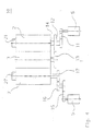
- FIG. 5 A control known in printing press construction is shown schematically in FIG. 5.
- the load 25 is a heavy roller or a heavy one Cylinder or a corresponding roller or cylinder system, the Mass moment of inertia typically more than five times that of motor 5 is. Nevertheless, the control of this motor / load system should be optimized for performance and with sufficiently high control quality for the speed or the angular position and the speed of the Load 25 are regulated. There should be no connection to the coupling 24 of the motor and the load high demands are made with regard to their torsional rigidity and Freedom of play.
- This system runs from the load to the motor in large mass inertia conditions quickly to its dynamic limits. If the control becomes unstable, it vibrates above all the engine while the load remains relatively calm.
- FIG. 6 shows a control in which, as already shown in FIG. 4, the Reference variable for the control is generated by an encoder 21 which is connected to the load 25 and is not attached to the engine 5.
- This actual value transmitter 21 is at the free shaft end the load, in the embodiment at the free shaft end of the blanket cylinder 2 one Cylinder group 10 attached.
- This actual value transmitter 21 is therefore in the following Called loader.
- the coupling 24 is through the toothed belt already described 11 with high elasticity compared to a direct coupling or a gear coupling but also high damping. In addition, this coupling 24 with one Timing belt without play.
- the actual value required for the control generated by the load transmitter 21, which is the angular position the blanket cylinder 2 or its speed and its angular position, is returned to the controller 23.
- a computer generated setpoint from that Setpoint generator 22 is compared with this actual value and to form a control signal used for the engine 5.
- the coupling 24 and the load 25 lie within the actual one Control loop.
- the load and the coupling 24 form a low-pass filter for those in the Control system creates shocks and vibrations, which are therefore only reduced Dimensions are returned in the controller 23 and therefore not too undesirable Can lead suggestions of the scheme.
- This is the dynamic and also the Control quality compared to conventional systems even with otherwise the same Coupling significantly increased.
- the system consisting of controller, motor, clutch and Cylinder is already much more damped. Exaggerated resonance occurs therefore not to the same extent. The controller can therefore be set more quickly without leaving the stable work area.
- a possibly attached to the motor 5, in the exemplary embodiment according to FIG. 6 The actual value detection shown can be used for additional monitoring of the motor 5 Example can be used with a desired emergency shutdown option of the engine 5.
- FIGS. 7 and 8 compare the dynamic behavior of the two controls according to FIGS. 5 and 6.
- the reciprocal value of the reset time T i of the drive is selected as a measure of the dynamics of the control.
- FIG. 7 shows the dynamics as a function of the mass inertia ratio from load to motor with identical coupling and identical phase reserve. This clearly shows that the control according to FIG. 6 with the actual value detection on the load is clearly superior to the actual value detection on the motor, in accordance with FIG.
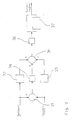
- the setpoint and the actual value in the exemplary embodiment the setpoint or actual center position of a blanket cylinder 2, are fed to a first differential amplifier 31 to form the difference between the setpoint and actual value.
- the difference D 1 formed there is fed to a first proportional amplifier 34 and applied to a second differential amplifier 35 as a proportionally amplified signal K 1 XD 1 .
- the setpoint and the actual value are each fed to a differentiating element 32 or 33, differentiated and the corresponding output signals S s and S i are fed to the second differential amplifier 35.
- the sum k 1 D 1 + S s - S i formed there is amplified in a second proportional amplifier 36 and fed to a current regulator for the motor 5 via an integrating element 37.
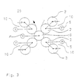
- FIG. 10 shows a pressure point which is formed by three cylinder groups 10.
- a first cylinder group 10 is on one printing side of the paper web 1, and a second and a third cylinder group 10 are on the opposite pressure side thereof Paper web 1 arranged.
- the two on the same print side of paper web 1 arranged cylinder groups 10 are mutually on the rubber cylinder 2 of the first Cylinder group 10 adjustable. This is indicated by two straight arrows W.
- Each cylinder group 10 is again from an engine 5, as is already the case with the two cylinder groups 10 of FIG. 1 has been individually driven.
- This arrangement enables the on-the-fly change of production at continuous Continuous paper web 1.
- One of the two swiveling rubber cylinders 2 is pivoted away while the other is in the pressure position to the opposite Rubber cylinder 2 of the first cylinder group 10 stands.
- the production change takes place in known way by changing the plates of the pivoted Blanket cylinder 2 assigned plate cylinder 3rd
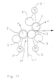
- Figure 11 shows an alternative pressure point also with three cylinder groups 10. Das for the arrangement of FIG. 10, what has been said in principle also applies to the arrangement of FIG 11. While the three cylinder groups 10 of the arrangement of Figure 10 each Form legs of a "Y", the cylinder groups 10 of Figure 11 form an upside down standing "Y" or a "Lambda”. In the arrangement according to FIG. 11, the two are lower, horizontally opposite cylinder groups 10 in the Machine frame stored independently of the upper cylinder group 10. These two lower cylinder groups 10 thereby form the assembly or cylinder unit 20.
- Figures 10 and 11 show the high flexibility of the invention Formation of cylinder groups and the regulation of each according to the invention Cylinder group. The most varied can be done in a particularly simple manner Form pressure points by, for example, cylinder units 20 with cylinder groups 10 (Fig. 10 and 11) or a plurality of cylinder units 20 are arranged one above the other (Fig. 1).
- the cylinders of the arrangements according to FIGS. 10 and 11 can also be coupled in a different way than that according to FIGS. 1 to 4, for example via a single gear.
Landscapes
- Engineering & Computer Science (AREA)
- Mechanical Engineering (AREA)
- Rotary Presses (AREA)
- Inking, Control Or Cleaning Of Printing Machines (AREA)
- Screen Printers (AREA)
- Treatment Of Fiber Materials (AREA)
- Printing Plates And Materials Therefor (AREA)
- Soil Working Implements (AREA)
- Glass Compositions (AREA)
- Impact Printers (AREA)
- Switches With Compound Operations (AREA)
- Holding Or Fastening Of Disk On Rotational Shaft (AREA)
- Lubrication Of Internal Combustion Engines (AREA)
- Soft Magnetic Materials (AREA)
- Fixed Capacitors And Capacitor Manufacturing Machines (AREA)
- Auxiliary Devices For And Details Of Packaging Control (AREA)
Applications Claiming Priority (8)
| Application Number | Priority Date | Filing Date | Title |
|---|---|---|---|
| DE4344896A DE4344896C5 (de) | 1993-12-29 | 1993-12-29 | Antrieb für Zylinder einer Rollenrotationsdruckmaschine |
| DE4344912 | 1993-12-29 | ||
| DE19934344912 DE4344912C5 (de) | 1993-12-29 | 1993-12-29 | Antrieb eines farbübertragenden Druckzylinders einer Rollenrotationsdruckmaschine |
| DE4344896 | 1993-12-29 | ||
| DE4405658 | 1994-02-22 | ||
| DE4405658A DE4405658C5 (de) | 1993-12-29 | 1994-02-22 | Antrieb für Zylinder einer Rollenrotationsdruckmaschine |
| EP94810752A EP0644048B2 (fr) | 1993-12-29 | 1994-12-27 | Machine d'impression rotative, avec des cylindres porte-blanchet et porte-clichés réunisen groupes de cylindres par paires |
| EP99106201A EP0930160B1 (fr) | 1993-12-29 | 1994-12-27 | Machine d'impression rotative |
Related Parent Applications (3)
| Application Number | Title | Priority Date | Filing Date |
|---|---|---|---|
| EP94810752.9 Division | 1994-12-27 | ||
| EP99106201A Division EP0930160B1 (fr) | 1993-12-29 | 1994-12-27 | Machine d'impression rotative |
| EP99106201.9 Division | 1999-04-09 |
Publications (3)
| Publication Number | Publication Date |
|---|---|
| EP1155826A2 true EP1155826A2 (fr) | 2001-11-21 |
| EP1155826A3 EP1155826A3 (fr) | 2002-06-26 |
| EP1155826B1 EP1155826B1 (fr) | 2011-09-14 |
Family
ID=27205938
Family Applications (4)
| Application Number | Title | Priority Date | Filing Date |
|---|---|---|---|
| EP99106201A Expired - Lifetime EP0930160B1 (fr) | 1993-12-29 | 1994-12-27 | Machine d'impression rotative |
| EP99106200A Expired - Lifetime EP0930159B1 (fr) | 1993-12-29 | 1994-12-27 | Machine rotative d'impression |
| EP01116647A Expired - Lifetime EP1155826B1 (fr) | 1993-12-29 | 1994-12-27 | Machine rotative d'impression |
| EP94810752A Expired - Lifetime EP0644048B2 (fr) | 1993-12-29 | 1994-12-27 | Machine d'impression rotative, avec des cylindres porte-blanchet et porte-clichés réunisen groupes de cylindres par paires |
Family Applications Before (2)
| Application Number | Title | Priority Date | Filing Date |
|---|---|---|---|
| EP99106201A Expired - Lifetime EP0930160B1 (fr) | 1993-12-29 | 1994-12-27 | Machine d'impression rotative |
| EP99106200A Expired - Lifetime EP0930159B1 (fr) | 1993-12-29 | 1994-12-27 | Machine rotative d'impression |
Family Applications After (1)
| Application Number | Title | Priority Date | Filing Date |
|---|---|---|---|
| EP94810752A Expired - Lifetime EP0644048B2 (fr) | 1993-12-29 | 1994-12-27 | Machine d'impression rotative, avec des cylindres porte-blanchet et porte-clichés réunisen groupes de cylindres par paires |
Country Status (8)
| Country | Link |
|---|---|
| EP (4) | EP0930160B1 (fr) |
| JP (2) | JP3424999B2 (fr) |
| CN (1) | CN1061301C (fr) |
| AT (4) | ATE524311T1 (fr) |
| DE (3) | DE59408463D1 (fr) |
| DK (3) | DK0930159T3 (fr) |
| ES (3) | ES2135557T5 (fr) |
| RU (1) | RU2127668C1 (fr) |
Cited By (2)
| Publication number | Priority date | Publication date | Assignee | Title |
|---|---|---|---|---|
| EP2153992A1 (fr) * | 2008-08-13 | 2010-02-17 | Komori Corporation | Procédé et dispositif pour commander une imprimante |
| EP2177358A1 (fr) * | 2008-10-15 | 2010-04-21 | Komori Corporation | Procédé et dispositif pour comander une machine |
Families Citing this family (62)
| Publication number | Priority date | Publication date | Assignee | Title |
|---|---|---|---|---|
| DE4322744C2 (de) † | 1993-07-08 | 1998-08-27 | Baumueller Nuernberg Gmbh | Elektrisches Antriebssystem und Positionierverfahren zur synchronen Verstellung mehrerer dreh- und/oder verschwenkbarer Funktionsteile in Geräten und Maschinen, Antriebsanordnung mit einem Winkellagegeber und Druckmaschine |
| DE4430693B4 (de) * | 1994-08-30 | 2005-12-22 | Man Roland Druckmaschinen Ag | Antriebe für eine Rollenrotations-Offsetdruckmaschine |
| US6644184B1 (en) | 1995-02-09 | 2003-11-11 | Man Roland Druckmaschinen Ag | Offset printing machine |
| DE29522290U1 (de) * | 1994-08-30 | 2001-03-29 | Man Roland Druckmaschinen Ag, 63069 Offenbach | Offsetdruckmaschine |
| DE19603663A1 (de) * | 1996-02-02 | 1997-08-07 | Roland Man Druckmasch | Druckwerk für den fliegenden Druckplattenwechsel |
| CH691225A8 (fr) * | 1996-02-09 | 2001-08-15 | Bobst Sa | Machine d'impression rotative. |
| DE19623223C2 (de) * | 1996-06-11 | 2001-05-17 | Roland Man Druckmasch | Antrieb für eine Druckmaschine |
| DE19629605C2 (de) * | 1996-07-23 | 2000-02-03 | Koenig & Bauer Ag | Antrieb einer Druckeinheit |
| DE29702923U1 (de) * | 1997-02-19 | 1997-03-27 | Maschinenfabrik Wifag, Bern | Zylindereinheit für eine Rollenrotationsdruckmaschine |
| DE59802993D1 (de) * | 1997-03-04 | 2002-03-21 | Roland Man Druckmasch | Offsetdruckmaschine für schnellen Produktionswechsel |
| US6050185A (en) * | 1997-11-26 | 2000-04-18 | Heidelberger Druckmaschinen Ag | Printing unit for a web-fed rotary printing press |
| US6374731B1 (en) * | 1997-04-18 | 2002-04-23 | Heidelberger Druckmaschinen Ag | Lithographic newspaper printing press |
| DE59806836D1 (de) * | 1997-05-28 | 2003-02-06 | Koenig & Bauer Ag | Antrieb für einen Zylinder einer Rotationsdruckmaschine |
| DE19723043C2 (de) * | 1997-06-02 | 2002-08-01 | Wifag Maschf | Verfahren und Vorrichtung zur Regelung eines Umfangregisters von auf eine Bahn druckenden Zylindern einer Rollenrotationsdruckmaschine |
| DE19723059A1 (de) * | 1997-06-02 | 1998-12-03 | Wifag Maschf | Registerhaltige Abstimmung von Druckzylindern einer Rollenrotationsmaschine |
| DE59809058D1 (de) | 1997-06-02 | 2003-08-28 | Wifag Maschf | Registerhaltige Abstimmung von Druckzylindern einer Rollenrotationsmaschine |
| DE19724765A1 (de) * | 1997-06-12 | 1998-12-17 | Roland Man Druckmasch | Antrieb für ein Druckwerk einer Rotationsdruckmaschine |
| DE19732330C2 (de) * | 1997-07-28 | 2001-04-19 | Koenig & Bauer Ag | Antrieb für eine Druckeinheit |
| JP3037650B2 (ja) * | 1997-10-29 | 2000-04-24 | 株式会社東京機械製作所 | 輪転機の印刷ユニットの駆動装置 |
| DE19820271C2 (de) * | 1997-11-14 | 2000-05-25 | Baumueller Nuernberg Gmbh | Antriebsanordnung mit einem oder mehreren Elektromotoren |
| DE19755316C2 (de) * | 1997-12-12 | 1999-10-07 | Koenig & Bauer Ag | Antrieb für Zylinder einer Druckeinheit |
| DE19860540A1 (de) * | 1998-12-30 | 2000-07-20 | Koenig & Bauer Ag | Mehrfarben-Rollenrotationsdruckmaschine |
| EP1048460A3 (fr) * | 1999-04-22 | 2002-10-09 | Maschinenfabrik Wifag | Influence de la déformation en éventail dans l'impression en offset humide rotative |
| US6345574B1 (en) * | 2000-05-17 | 2002-02-12 | Heidelberger, Druckmaschinen Ag | Printing unit arrangement in a web-fed rotary printing press |
| DE10045372C2 (de) * | 2000-05-17 | 2002-04-18 | Koenig & Bauer Ag | Falzapparat einer Rotationsdruckmaschine |
| DE10046365B4 (de) * | 2000-09-20 | 2004-09-23 | Koenig & Bauer Ag | Verfahren und Vorrichtung zum Antrieb einer Druckeinheit |
| DE10046366C2 (de) * | 2000-09-20 | 2002-11-14 | Koenig & Bauer Ag | Antrieb einer Druckeinheit |
| DE10046377B4 (de) * | 2000-09-20 | 2006-02-09 | Koenig & Bauer Ag | Antrieb einer Druckeinheit |
| DE10046376C2 (de) | 2000-09-20 | 2002-12-12 | Koenig & Bauer Ag | Antrieb einer Druckeinheit |
| DE10046368C2 (de) * | 2000-09-20 | 2003-02-06 | Koenig & Bauer Ag | Antrieb einer Druckeinheit |
| DE10046375B4 (de) * | 2000-09-20 | 2005-04-07 | Koenig & Bauer Ag | Antrieb einer Druckeinheit |
| DE10046367B4 (de) * | 2000-09-20 | 2005-10-13 | Koenig & Bauer Ag | Antrieb einer Druckeinheit |
| US7216585B2 (en) | 2001-01-24 | 2007-05-15 | Goss International Americas, Inc. | Shaftless motor drive for a printing press with an anilox inker |
| DE10113338B4 (de) * | 2001-03-20 | 2004-10-28 | Koenig & Bauer Ag | Verfahren und Vorrichtungen zum Antrieb einer Druckeinheit |
| DE10114801B4 (de) * | 2001-03-26 | 2005-10-13 | Koenig & Bauer Ag | Antrieb eines Druckwerks |
| DE10154838A1 (de) * | 2001-11-08 | 2003-05-22 | Koenig & Bauer Ag | Antrieb eines Druckwerks |
| ATE555907T1 (de) | 2001-03-26 | 2012-05-15 | Koenig & Bauer Ag | Druckwerk einer druckmaschine |
| ATE327099T1 (de) | 2001-03-26 | 2006-06-15 | Koenig & Bauer Ag | Antrieb eines druckwerks |
| DE20221647U1 (de) | 2001-10-05 | 2006-09-28 | Koenig & Bauer Ag | Rollenrotationsdruckmaschine |
| EP1938975A3 (fr) | 2001-11-08 | 2013-08-28 | Koenig & Bauer AG | Dispositif d'entrainement d'un groupe d'impression |
| DE502004009017D1 (de) * | 2003-07-11 | 2009-04-02 | Koenig & Bauer Ag | Rollenrotationsdruckmaschine |
| US7383771B2 (en) * | 2003-12-05 | 2008-06-10 | Man Roland Druckmaschinen Ag | Web-fed rotary printing unit |
| US7392740B2 (en) * | 2003-12-05 | 2008-07-01 | Man Roland Druckmachinen Ag | Web fed rotary printing unit |
| ATE433802T1 (de) * | 2003-12-12 | 2009-07-15 | Wifag Maschf Ag | Aussenläuferantrieb |
| EP1568493A1 (fr) | 2004-02-27 | 2005-08-31 | Müller Martini Holding AG | Dispositif d'impression à format variable ou dispositif à insérer pour l'impression offset. |
| DE102004051686B4 (de) * | 2004-07-13 | 2007-10-31 | Man Roland Druckmaschinen Ag | Verfahren zur Regelung einer Rollenrotationsdruckeinheit |
| US7775159B2 (en) | 2005-03-30 | 2010-08-17 | Goss International Americas, Inc. | Cantilevered blanket cylinder lifting mechanism |
| WO2006104830A2 (fr) | 2005-03-30 | 2006-10-05 | Goss International Americas, Inc. | Presse a imprimer offset sur papier sans fin pourvue d'une lame plieuse articulee |
| CN101208201B (zh) | 2005-03-30 | 2011-10-05 | 高斯国际美洲公司 | 具有自动装版的卷筒纸胶印印刷机 |
| JP4814309B2 (ja) | 2005-03-30 | 2011-11-16 | ゴス インターナショナル アメリカス インコーポレイテッド | ブランケット胴胴抜き支持面を有する印刷ユニット |
| JP4829291B2 (ja) | 2005-04-11 | 2011-12-07 | ゴス インターナショナル アメリカス インコーポレイテッド | 単一モータ駆動を用いて自動プレーティングを可能にする印刷ユニット |
| DE102006010602A1 (de) * | 2006-03-06 | 2007-09-20 | Maschinenfabrik Wifag | Falzvorrichtung mit auf unterschiedlichen Höhen angeordneten Falzapparaten |
| DE102006011412B4 (de) | 2006-03-11 | 2014-07-10 | manroland sheetfed GmbH | Druckmaschine und Verfahren zum Betreiben derselben |
| JP2008037037A (ja) * | 2006-08-09 | 2008-02-21 | Komori Corp | 凹版印刷機 |
| DE102006046894B4 (de) | 2006-10-04 | 2010-05-27 | Wifag Maschinenfabrik Ag | Verfahren zum Anfahren einer Rollenrotationsdruckmaschine |
| DE102008012385A1 (de) | 2008-03-04 | 2009-09-10 | Wifag Maschinenfabrik Ag | Offsetdruck mit reduziertem Farbauftrag |
| DE102008054192A1 (de) | 2008-10-31 | 2010-05-06 | Manroland Ag | Druckeinheit |
| DE102009045679B4 (de) | 2009-10-14 | 2013-01-17 | Koenig & Bauer Aktiengesellschaft | Verfahren zur Regelung eines Antriebes wenigstens eines registerhaltig anzutreibenden Rotationskörpers einer Druckmaschine |
| DE102009047356A1 (de) * | 2009-12-01 | 2011-06-09 | Manroland Ag | Druckeinheit einer Rollendruckmaschine |
| DE102011118904A1 (de) * | 2010-12-20 | 2012-06-21 | Heidelberger Druckmaschinen Ag | Produktionswerk mit Einzelantrieb |
| DE102012206802B4 (de) | 2012-04-25 | 2015-04-02 | Koenig & Bauer Aktiengesellschaft | Druckeinheit mit wenigstens zwei mechanisch unabhängig voneinander angetriebenen, ein Doppeldruckwerk ausbildenden Druckwerken |
| CN102896893B (zh) * | 2012-11-13 | 2015-09-09 | 潍坊永昱电控科技有限公司 | 一种彩色印刷机用印刷物台套准构件 |
Family Cites Families (37)
| Publication number | Priority date | Publication date | Assignee | Title |
|---|---|---|---|---|
| GB137708A (en) † | 1919-04-11 | 1920-01-22 | Louis Barrow | Improvements relating to mechanically propelled road vehicles |
| US2890653A (en) * | 1955-03-30 | 1959-06-16 | Jerome R Share | Rotary printing press for continuous metal strip |
| US3221651A (en) * | 1962-08-03 | 1965-12-07 | Ohg Cigardi S P A | Multi-units sheet-fed printing machine drive |
| US3557692A (en) * | 1968-09-09 | 1971-01-26 | Harris Intertype Corp | Plural independently operable motor drive arrangement in printing press |
| GB1262116A (en) † | 1969-04-21 | 1972-02-02 | Bobst Fils Sa J | Inserter and splicer with register control for a preprinted web |
| SE342407B (fr) * | 1970-07-10 | 1972-02-07 | Printing Equipment Ab | |
| BE789456A (fr) † | 1971-10-08 | 1973-01-15 | Bobst Fils Sa J | Procede et dispositif de correction du reperage d'images dans une machine a plusieurs stations |
| DE2529009B2 (de) † | 1975-06-28 | 1977-08-04 | Rollenrotationsdruckmaschine fuer wertpapiere | |
| FR2320185A1 (fr) † | 1975-08-08 | 1977-03-04 | Chambon Machines | Dispositif de reperage des couleurs pour impression sur materiaux legers |
| JPS56111669A (en) * | 1980-02-06 | 1981-09-03 | Tokyo Kikai Seisakusho:Kk | Printing mode switching device in blanket drum of offset rotary printing press |
| EP0084698B1 (fr) † | 1982-01-26 | 1986-09-17 | John Henry Morgan | Appareil et méthode pour varier l'emplacement d'une opération effectuée sur un élément allongé mobile |
| JPS58152737A (ja) * | 1982-03-09 | 1983-09-10 | Fuji Xerox Co Ltd | 紙の搬送装置 |
| US4495582A (en) * | 1982-06-04 | 1985-01-22 | Harris Graphics Corporation | Control system for pre-setting and operation of a printing press and collator |
| DE3317981C2 (de) * | 1983-05-18 | 1986-10-16 | Metronic Gerätebau GmbH & Co, 8707 Veitshöchheim | Druckwerk für den Verpackungsdruck |
| GB2146291B (en) * | 1983-09-14 | 1987-10-14 | Grace W R & Co | Rotary printing press |
| GB2149149A (en) * | 1983-10-28 | 1985-06-05 | Rockwell Graphic Syst | Printing press synchronization |
| DE3342662A1 (de) * | 1983-11-25 | 1985-06-05 | M.A.N.- Roland Druckmaschinen AG, 6050 Offenbach | Vorrichtung an einer druckmaschine, bestehend aus einem platten- und/oder gummizylinder |
| DE3409194A1 (de) * | 1984-03-14 | 1985-09-26 | Heidelberger Druckmaschinen Ag, 6900 Heidelberg | Registerstellvorrichtung fuer eine rotationsdruckmaschine |
| GB2156108B (en) * | 1984-03-17 | 1987-09-03 | Fin Machine Company Limited Th | Processing machine for strip material |
| JPS60250955A (ja) * | 1984-05-26 | 1985-12-11 | Hamada Insatsuki Seizosho:Kk | プリンタ・スロツタ |
| US4839814A (en) * | 1985-01-29 | 1989-06-13 | Moore Business Forms, Inc. | Size independent modular web processing line and modules |
| JPH064219B2 (ja) * | 1985-02-07 | 1994-01-19 | 住友金属工業株式会社 | ワイヤ式切断加工装置の溝ロ−ラ駆動方法 |
| JPS6255136A (ja) * | 1985-09-05 | 1987-03-10 | Tokyo Kikai Seisakusho:Kk | オフセツト輪転印刷機 |
| JPS63236651A (ja) * | 1987-03-25 | 1988-10-03 | Hitachi Seiko Ltd | 印刷機の駆動装置 |
| JPH0813542B2 (ja) * | 1987-05-27 | 1996-02-14 | 東洋電機製造株式会社 | 印刷機械の駆動方法 |
| DE3729911A1 (de) * | 1987-09-07 | 1989-03-23 | Braun Gmbh Ind Elektronik | Gleichlauf-regelung von bearbeitungsstationen |
| DE3905341A1 (de) * | 1988-03-30 | 1989-10-19 | Kloeckner Humboldt Deutz Ag | Zentrifugalapparat |
| DE3828638C1 (fr) * | 1988-08-24 | 1989-07-27 | Heidelberger Druckmaschinen Ag, 6900 Heidelberg, De | |
| JPH02235745A (ja) * | 1989-03-10 | 1990-09-18 | J P Ii Kk | 印刷機の給湿装置 |
| JPH0688401B2 (ja) † | 1989-09-22 | 1994-11-09 | 剛一 中本 | 輪転印刷機 |
| JP2589863B2 (ja) * | 1990-04-25 | 1997-03-12 | ハマダ印刷機械株式会社 | 印刷機 |
| JP2885479B2 (ja) * | 1990-06-19 | 1999-04-26 | 株式会社小森コーポレーション | 印刷機の動力開放機構 |
| DE4116415C2 (de) * | 1991-05-18 | 1993-10-14 | Roland Man Druckmasch | Druckwerk für den Mehrfarbendruck |
| DE4137979B4 (de) * | 1991-11-19 | 2004-05-06 | Heidelberger Druckmaschinen Ag | Antrieb für eine Druckmaschine mit mindestens zwei mechanisch voneinander entkoppelten Druckwerken |
| DE4138479C3 (de) * | 1991-11-22 | 1998-01-08 | Baumueller Nuernberg Gmbh | Verfahren und Anordnung für einen Elektromotor zum Antrieb eines Drehkörpers, insbesondere des druckgebenden Zylinders einer Druckmaschine |
| US5235913A (en) * | 1991-12-10 | 1993-08-17 | United States Can Company | Litho start-off device and method of stabilizing an offset lithographic printing press to print a precise ink image |
| DE4214394C2 (de) * | 1992-04-30 | 1998-08-20 | Asea Brown Boveri | Antriebsvorrichtung für eine längswellenlose Rotationsdruckmaschine |
-
1994
- 1994-12-27 AT AT01116647T patent/ATE524311T1/de active
- 1994-12-27 DK DK99106200T patent/DK0930159T3/da active
- 1994-12-27 AT AT99106201T patent/ATE216317T1/de active
- 1994-12-27 ES ES94810752T patent/ES2135557T5/es not_active Expired - Lifetime
- 1994-12-27 EP EP99106201A patent/EP0930160B1/fr not_active Expired - Lifetime
- 1994-12-27 ES ES99106201T patent/ES2175867T3/es not_active Expired - Lifetime
- 1994-12-27 DE DE59408463T patent/DE59408463D1/de not_active Expired - Lifetime
- 1994-12-27 ES ES99106200T patent/ES2157676T3/es not_active Expired - Lifetime
- 1994-12-27 DK DK94810752T patent/DK0644048T4/da active
- 1994-12-27 DK DK99106201T patent/DK0930160T3/da active
- 1994-12-27 EP EP99106200A patent/EP0930159B1/fr not_active Expired - Lifetime
- 1994-12-27 DE DE59409732T patent/DE59409732D1/de not_active Expired - Lifetime
- 1994-12-27 EP EP01116647A patent/EP1155826B1/fr not_active Expired - Lifetime
- 1994-12-27 DE DE59410108T patent/DE59410108D1/de not_active Expired - Lifetime
- 1994-12-27 AT AT94810752T patent/ATE181879T1/de active
- 1994-12-27 AT AT99106200T patent/ATE200449T1/de active
- 1994-12-27 EP EP94810752A patent/EP0644048B2/fr not_active Expired - Lifetime
- 1994-12-29 RU RU94045261A patent/RU2127668C1/ru active
- 1994-12-29 CN CN94120462A patent/CN1061301C/zh not_active Expired - Fee Related
-
1995
- 1995-01-04 JP JP01554895A patent/JP3424999B2/ja not_active Expired - Fee Related
-
1999
- 1999-02-18 JP JP04026499A patent/JP3415469B2/ja not_active Expired - Fee Related
Cited By (4)
| Publication number | Priority date | Publication date | Assignee | Title |
|---|---|---|---|---|
| EP2153992A1 (fr) * | 2008-08-13 | 2010-02-17 | Komori Corporation | Procédé et dispositif pour commander une imprimante |
| CN101648457B (zh) * | 2008-08-13 | 2012-05-23 | 小森公司 | 处理机的驱动方法和装置 |
| US8950323B2 (en) | 2008-08-13 | 2015-02-10 | Komori Corporation | Method and apparatus for driving processor |
| EP2177358A1 (fr) * | 2008-10-15 | 2010-04-21 | Komori Corporation | Procédé et dispositif pour comander une machine |
Also Published As
| Publication number | Publication date |
|---|---|
| EP0930159A1 (fr) | 1999-07-21 |
| EP1155826A3 (fr) | 2002-06-26 |
| DE59408463D1 (de) | 1999-08-12 |
| CN1122279A (zh) | 1996-05-15 |
| ES2135557T3 (es) | 1999-11-01 |
| DK0644048T3 (da) | 2000-01-31 |
| DE59409732D1 (de) | 2001-05-17 |
| EP0930160A1 (fr) | 1999-07-21 |
| EP0644048A2 (fr) | 1995-03-22 |
| CN1061301C (zh) | 2001-01-31 |
| JPH0834108A (ja) | 1996-02-06 |
| JP3415469B2 (ja) | 2003-06-09 |
| ATE216317T1 (de) | 2002-05-15 |
| EP0644048B1 (fr) | 1999-07-07 |
| ES2175867T3 (es) | 2002-11-16 |
| DK0930160T3 (da) | 2002-07-29 |
| DK0930159T3 (da) | 2001-08-13 |
| EP1155826B1 (fr) | 2011-09-14 |
| ES2135557T5 (es) | 2005-09-01 |
| DK0644048T4 (da) | 2005-05-02 |
| ATE524311T1 (de) | 2011-09-15 |
| JP3424999B2 (ja) | 2003-07-07 |
| JPH11268249A (ja) | 1999-10-05 |
| ATE181879T1 (de) | 1999-07-15 |
| EP0644048A3 (fr) | 1995-06-28 |
| ATE200449T1 (de) | 2001-04-15 |
| RU2127668C1 (ru) | 1999-03-20 |
| ES2157676T3 (es) | 2001-08-16 |
| DE59410108D1 (de) | 2002-05-23 |
| EP0644048B2 (fr) | 2005-03-23 |
| RU94045261A (ru) | 1996-12-10 |
| EP0930159B1 (fr) | 2001-04-11 |
| EP0930160B1 (fr) | 2002-04-17 |
Similar Documents
| Publication | Publication Date | Title |
|---|---|---|
| EP0930159B1 (fr) | Machine rotative d'impression | |
| DE4345570B4 (de) | Antrieb für Zylinder einer Rotationsdruckmaschine | |
| EP1277575B1 (fr) | Presse d'impression offset | |
| EP0741020B2 (fr) | Machine d'impression rotative comprenant un appareil de pliage à assemblage libre | |
| EP1040917B1 (fr) | Procédé et dispositif à compensation de vibrations torsionelles d'une machine à imprimer | |
| EP0741019B1 (fr) | Appareil de pliage entraíné individuellement pour une machine d'impression rotative | |
| DE10121245A1 (de) | Druckwerksanordnung in einer Rollenrotationsdruckmaschine | |
| DE4344896C2 (de) | Antrieb für Zylinder einer Rollenrotationsdruckmaschine | |
| DE4344912C5 (de) | Antrieb eines farbübertragenden Druckzylinders einer Rollenrotationsdruckmaschine | |
| EP1464488B1 (fr) | Imprimante | |
| DE102008048406A1 (de) | Vorrichtung zur Steuerung einer Bogenrotationsdruckmaschine mit mehreren Antriebsmotoren | |
| DE29513635U1 (de) | Rotationsdruckmaschine mit Zylindern, die zu motorisch einzeln angetriebenen Zylindergruppen zusammengefaßt sind | |
| DE4316261B4 (de) | Mehrmotorenantrieb für eine Bogen-Offset-Rotationsdruckmaschine | |
| DE10212534B4 (de) | Verfahren zum Antreiben einer Druckmaschine | |
| DE9421938U1 (de) | Rotationsdruckmaschine mit paarweise zu Zylindergruppen zusammengefaßten Gummituch- und Platten- bzw. Formzylindern | |
| EP1110722B1 (fr) | Presse d'impression offset | |
| EP2002979A1 (fr) | Dispositif d'encrage pour une machine à imprimer et procédé de commande d'un dispositif d'encrage | |
| EP0668160A1 (fr) | Dispositif pour l'entraînement synchrone de plusieurs arbres d'une installation | |
| DE102008010009A1 (de) | Vorrichtung zur Druckan- und Druckabstellung eines Gummizylinders zu einem Plattenzylinder und einem Druckzylinder |
Legal Events
| Date | Code | Title | Description |
|---|---|---|---|
| PUAI | Public reference made under article 153(3) epc to a published international application that has entered the european phase |
Free format text: ORIGINAL CODE: 0009012 |
|
| 17P | Request for examination filed |
Effective date: 20010713 |
|
| AC | Divisional application: reference to earlier application |
Ref document number: 930160 Country of ref document: EP Ref document number: 644048 Country of ref document: EP |
|
| AK | Designated contracting states |
Kind code of ref document: A2 Designated state(s): AT BE CH DE DK ES FR GB IT LI LU NL SE |
|
| AX | Request for extension of the european patent |
Free format text: LT;SI |
|
| RIN1 | Information on inventor provided before grant (corrected) |
Inventor name: MIESCHER, ANDREAS Inventor name: SCHNEIDER, FELIX Inventor name: ZAHND, ANDREAS Inventor name: KOCH, DIETER |
|
| PUAL | Search report despatched |
Free format text: ORIGINAL CODE: 0009013 |
|
| AK | Designated contracting states |
Kind code of ref document: A3 Designated state(s): AT BE CH DE DK ES FR GB IT LI LU NL SE |
|
| AX | Request for extension of the european patent |
Free format text: LT;SI |
|
| AKX | Designation fees paid |
Designated state(s): AT BE CH DE DK ES FR GB IT LI LU NL SE |
|
| RAP1 | Party data changed (applicant data changed or rights of an application transferred) |
Owner name: WIFAG MASCHINENFABRIK AG |
|
| 17Q | First examination report despatched |
Effective date: 20090402 |
|
| GRAP | Despatch of communication of intention to grant a patent |
Free format text: ORIGINAL CODE: EPIDOSNIGR1 |
|
| GRAS | Grant fee paid |
Free format text: ORIGINAL CODE: EPIDOSNIGR3 |
|
| GRAA | (expected) grant |
Free format text: ORIGINAL CODE: 0009210 |
|
| AC | Divisional application: reference to earlier application |
Ref document number: 0644048 Country of ref document: EP Kind code of ref document: P Ref document number: 0930160 Country of ref document: EP Kind code of ref document: P |
|
| AK | Designated contracting states |
Kind code of ref document: B1 Designated state(s): AT BE CH DE DK ES FR GB IT LI LU NL SE |
|
| REG | Reference to a national code |
Ref country code: GB Ref legal event code: FG4D Free format text: NOT ENGLISH |
|
| REG | Reference to a national code |
Ref country code: CH Ref legal event code: EP |
|
| REG | Reference to a national code |
Ref country code: DE Ref legal event code: R096 Ref document number: 59410464 Country of ref document: DE Effective date: 20111201 |
|
| REG | Reference to a national code |
Ref country code: NL Ref legal event code: VDEP Effective date: 20110914 |
|
| PG25 | Lapsed in a contracting state [announced via postgrant information from national office to epo] |
Ref country code: SE Free format text: LAPSE BECAUSE OF FAILURE TO SUBMIT A TRANSLATION OF THE DESCRIPTION OR TO PAY THE FEE WITHIN THE PRESCRIBED TIME-LIMIT Effective date: 20110914 |
|
| PG25 | Lapsed in a contracting state [announced via postgrant information from national office to epo] |
Ref country code: NL Free format text: LAPSE BECAUSE OF FAILURE TO SUBMIT A TRANSLATION OF THE DESCRIPTION OR TO PAY THE FEE WITHIN THE PRESCRIBED TIME-LIMIT Effective date: 20110914 |
|
| BERE | Be: lapsed |
Owner name: WIFAG MASCHINENFABRIK AG Effective date: 20111231 |
|
| PLBE | No opposition filed within time limit |
Free format text: ORIGINAL CODE: 0009261 |
|
| STAA | Information on the status of an ep patent application or granted ep patent |
Free format text: STATUS: NO OPPOSITION FILED WITHIN TIME LIMIT |
|
| PG25 | Lapsed in a contracting state [announced via postgrant information from national office to epo] |
Ref country code: DK Free format text: LAPSE BECAUSE OF FAILURE TO SUBMIT A TRANSLATION OF THE DESCRIPTION OR TO PAY THE FEE WITHIN THE PRESCRIBED TIME-LIMIT Effective date: 20110914 |
|
| 26N | No opposition filed |
Effective date: 20120615 |
|
| GBPC | Gb: european patent ceased through non-payment of renewal fee |
Effective date: 20111227 |
|
| REG | Reference to a national code |
Ref country code: DE Ref legal event code: R097 Ref document number: 59410464 Country of ref document: DE Effective date: 20120615 |
|
| PG25 | Lapsed in a contracting state [announced via postgrant information from national office to epo] |
Ref country code: BE Free format text: LAPSE BECAUSE OF NON-PAYMENT OF DUE FEES Effective date: 20111231 Ref country code: GB Free format text: LAPSE BECAUSE OF NON-PAYMENT OF DUE FEES Effective date: 20111227 |
|
| REG | Reference to a national code |
Ref country code: AT Ref legal event code: MM01 Ref document number: 524311 Country of ref document: AT Kind code of ref document: T Effective date: 20111227 |
|
| PG25 | Lapsed in a contracting state [announced via postgrant information from national office to epo] |
Ref country code: ES Free format text: LAPSE BECAUSE OF FAILURE TO SUBMIT A TRANSLATION OF THE DESCRIPTION OR TO PAY THE FEE WITHIN THE PRESCRIBED TIME-LIMIT Effective date: 20111225 |
|
| PG25 | Lapsed in a contracting state [announced via postgrant information from national office to epo] |
Ref country code: LU Free format text: LAPSE BECAUSE OF NON-PAYMENT OF DUE FEES Effective date: 20111227 |
|
| PG25 | Lapsed in a contracting state [announced via postgrant information from national office to epo] |
Ref country code: AT Free format text: LAPSE BECAUSE OF NON-PAYMENT OF DUE FEES Effective date: 20111227 |
|
| PGFP | Annual fee paid to national office [announced via postgrant information from national office to epo] |
Ref country code: CH Payment date: 20131218 Year of fee payment: 20 |
|
| PGFP | Annual fee paid to national office [announced via postgrant information from national office to epo] |
Ref country code: IT Payment date: 20131218 Year of fee payment: 20 Ref country code: FR Payment date: 20131213 Year of fee payment: 20 |
|
| PGFP | Annual fee paid to national office [announced via postgrant information from national office to epo] |
Ref country code: DE Payment date: 20131217 Year of fee payment: 20 |
|
| REG | Reference to a national code |
Ref country code: DE Ref legal event code: R071 Ref document number: 59410464 Country of ref document: DE |
|
| REG | Reference to a national code |
Ref country code: DE Ref legal event code: R071 Ref document number: 59410464 Country of ref document: DE |
|
| REG | Reference to a national code |
Ref country code: CH Ref legal event code: PL |