EP1155910A2 - Clignotant électronique programmable - Google Patents
Clignotant électronique programmable Download PDFInfo
- Publication number
- EP1155910A2 EP1155910A2 EP01111325A EP01111325A EP1155910A2 EP 1155910 A2 EP1155910 A2 EP 1155910A2 EP 01111325 A EP01111325 A EP 01111325A EP 01111325 A EP01111325 A EP 01111325A EP 1155910 A2 EP1155910 A2 EP 1155910A2
- Authority
- EP
- European Patent Office
- Prior art keywords
- voltage
- control unit
- stored
- volatile memory
- voltage threshold
- Prior art date
- Legal status (The legal status is an assumption and is not a legal conclusion. Google has not performed a legal analysis and makes no representation as to the accuracy of the status listed.)
- Withdrawn
Links
- 230000015654 memory Effects 0.000 claims abstract description 25
- 238000000034 method Methods 0.000 claims abstract description 23
- 238000012544 monitoring process Methods 0.000 claims abstract description 6
- 230000005540 biological transmission Effects 0.000 claims description 3
- 239000004020 conductor Substances 0.000 claims description 2
- 230000006870 function Effects 0.000 claims description 2
- 230000001939 inductive effect Effects 0.000 claims description 2
- 230000015572 biosynthetic process Effects 0.000 claims 1
- 238000001704 evaporation Methods 0.000 claims 1
- 238000010304 firing Methods 0.000 claims 1
- 230000007257 malfunction Effects 0.000 abstract description 6
- 238000005259 measurement Methods 0.000 abstract 2
- 230000001965 increasing effect Effects 0.000 description 3
- 230000004397 blinking Effects 0.000 description 2
- 239000003990 capacitor Substances 0.000 description 2
- 238000006243 chemical reaction Methods 0.000 description 2
- 230000002950 deficient Effects 0.000 description 2
- 238000004519 manufacturing process Methods 0.000 description 2
- 230000002411 adverse Effects 0.000 description 1
- 230000015556 catabolic process Effects 0.000 description 1
- 230000003247 decreasing effect Effects 0.000 description 1
- 238000006731 degradation reaction Methods 0.000 description 1
- 230000001419 dependent effect Effects 0.000 description 1
- 238000010586 diagram Methods 0.000 description 1
- 230000002349 favourable effect Effects 0.000 description 1
- 230000008439 repair process Effects 0.000 description 1
- 230000000717 retained effect Effects 0.000 description 1
- 230000008016 vaporization Effects 0.000 description 1
- 238000009834 vaporization Methods 0.000 description 1
Images
Classifications
-
- B—PERFORMING OPERATIONS; TRANSPORTING
- B60—VEHICLES IN GENERAL
- B60Q—ARRANGEMENT OF SIGNALLING OR LIGHTING DEVICES, THE MOUNTING OR SUPPORTING THEREOF OR CIRCUITS THEREFOR, FOR VEHICLES IN GENERAL
- B60Q1/00—Arrangement of optical signalling or lighting devices, the mounting or supporting thereof or circuits therefor
- B60Q1/26—Arrangement of optical signalling or lighting devices, the mounting or supporting thereof or circuits therefor the devices being primarily intended to indicate the vehicle, or parts thereof, or to give signals, to other traffic
- B60Q1/34—Arrangement of optical signalling or lighting devices, the mounting or supporting thereof or circuits therefor the devices being primarily intended to indicate the vehicle, or parts thereof, or to give signals, to other traffic for indicating change of drive direction
- B60Q1/38—Arrangement of optical signalling or lighting devices, the mounting or supporting thereof or circuits therefor the devices being primarily intended to indicate the vehicle, or parts thereof, or to give signals, to other traffic for indicating change of drive direction using immovably-mounted light sources, e.g. fixed flashing lamps
- B60Q1/385—Electronic temporisation with relay amplification
-
- B—PERFORMING OPERATIONS; TRANSPORTING
- B60—VEHICLES IN GENERAL
- B60Q—ARRANGEMENT OF SIGNALLING OR LIGHTING DEVICES, THE MOUNTING OR SUPPORTING THEREOF OR CIRCUITS THEREFOR, FOR VEHICLES IN GENERAL
- B60Q11/00—Arrangement of monitoring devices for devices provided for in groups B60Q1/00 - B60Q9/00
- B60Q11/005—Arrangement of monitoring devices for devices provided for in groups B60Q1/00 - B60Q9/00 for lighting devices, e.g. indicating if lamps are burning or not
- B60Q11/007—Arrangement of monitoring devices for devices provided for in groups B60Q1/00 - B60Q9/00 for lighting devices, e.g. indicating if lamps are burning or not the lighting devices indicating change of drive direction
Definitions
- the present invention relates to a method for monitoring a load circuit Flasher unit circuit, according to the preamble of claim 1.
- a disadvantage of the aforementioned method is that it measures the discharge time of the capacitor a complex analog-digital conversion circuit is necessary. Furthermore, in Each lamp circuit requires a switching transistor, its parameter spread and degradation adversely affects the reliability of the method.
- the lamp current flowing through a measuring resistor generates a voltage drop.
- Means a comparator the voltage value is compared with a predetermined value, whereby the threshold value is set directly when the circuit is manufactured.
- a disadvantage of the circuit mentioned is that the number and power of the used Flashing lights must be set during the production of the circuit and the Circuit not used simultaneously for a different number of flashing lights can be.
- Another method for monitoring a load circuit is from EP 0 870 646 A2 known.
- the failure of one is measured by means of a single measuring resistor or several flashing lights detected.
- the current flowing through the blinking lamps is led over the measuring resistor and the generated voltage drop compared with a predetermined voltage threshold.
- This The voltage threshold is obtained by using the Voltage value after switching on the ignition at the measuring resistor the first time
- Direction flashes measured and stored as a reference value in a volatile memory becomes.
- Another requirement is that the direction flashing is carried out at least twice becomes.
- a voltage threshold is generated. This is stored in a volatile memory filed.
- EP 0 870 646 A2 The disadvantage of the process described in EP 0 870 646 A2 is that after each Power supply failure, for example by disconnecting the battery Values of the voltage thresholds are deleted. Another determination of the voltage thresholds However, this can only be done with the ignition switched on and in connection with flash at least twice. Only then can the circuit detect any malfunction, such as the failure of flashing lights. However, if a flashing lamp is defective during the definition of the voltage threshold, or will if the direction flashing is not performed correctly, the circuit detects the Voltage threshold values incorrect. Until a new reset, this can lead to a permanent malfunction of the flasher unit. A failure of flashing lights will not occur or misidentified. Another disadvantage is that the flasher unit is also in the idle state Current is required to obtain the values of the voltage thresholds in the memories.
- the object of the present invention is to provide a method by which the internal Voltage thresholds are set independently of the operation of the flasher in the motor vehicle and can be changed if necessary and in particular the values of the voltage thresholds even when the supply voltage (battery voltage) is switched off stay. Another object is to implement a circuit arrangement to specify the method that can be produced easily and inexpensively.
- the essence of the invention is that for the monitoring of a load circuit in an electronic flasher unit one or more parameters that act as voltage thresholds be used in a non-volatile memory preferably before Applying a supply voltage.
- the characteristic values are determined the total power of the load elements at a given supply voltage.
- the voltage thresholds are then with the voltage value compared at the measuring resistor. Both the voltage thresholds, as well as that on the Measuring resistance measured voltage value are dependent on the operating voltage raised or lowered by the same amount. This is the result of the comparison regardless of the supply voltage. Since the storage of the characteristic values in one non-volatile memory, they are retained even after the supply voltage is switched off.
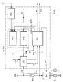
- FIG. 1 The invention is illustrated and explained below with reference to the drawing in FIG. 1:
- Fig. 1 block diagram to explain the method according to the invention.
- Multi-programmable memories can be used for the non-volatile memory EEPROMs, as well as easily programmable memories, for example Zap stages (shooting Zener diodes) or fuse stages (vaporization of conductor tracks), be used.
- the transmission of the characteristic values V20, VK0 for the voltage thresholds V2 or VK can be contactless, by means of inductive or infrared data transmission via the receiver RC, as well as by direct contacting, for example by means of a serial interface via the signal line D1.
Landscapes
- Engineering & Computer Science (AREA)
- Mechanical Engineering (AREA)
- Lighting Device Outwards From Vehicle And Optical Signal (AREA)
Applications Claiming Priority (2)
| Application Number | Priority Date | Filing Date | Title |
|---|---|---|---|
| DE10024042A DE10024042C1 (de) | 2000-05-16 | 2000-05-16 | Programmierbarer elektronischer Blinkgeber |
| DE10024042 | 2000-05-16 |
Publications (1)
| Publication Number | Publication Date |
|---|---|
| EP1155910A2 true EP1155910A2 (fr) | 2001-11-21 |
Family
ID=7642312
Family Applications (1)
| Application Number | Title | Priority Date | Filing Date |
|---|---|---|---|
| EP01111325A Withdrawn EP1155910A2 (fr) | 2000-05-16 | 2001-05-09 | Clignotant électronique programmable |
Country Status (4)
| Country | Link |
|---|---|
| US (1) | US20010043072A1 (fr) |
| EP (1) | EP1155910A2 (fr) |
| JP (1) | JP2001322487A (fr) |
| DE (1) | DE10024042C1 (fr) |
Families Citing this family (2)
| Publication number | Priority date | Publication date | Assignee | Title |
|---|---|---|---|---|
| JP4255632B2 (ja) * | 2001-11-07 | 2009-04-15 | 株式会社デンソー | 電気負荷の断線検出装置 |
| US7750501B2 (en) * | 2005-10-27 | 2010-07-06 | Continental Automotive Systems Us, Inc. | System and method of over voltage control for a power system |
Citations (6)
| Publication number | Priority date | Publication date | Assignee | Title |
|---|---|---|---|---|
| US4451822A (en) | 1980-09-17 | 1984-05-29 | Societe Nationale Industrielle Aerospatiale | Device for automatically checking a plurality of electric indicator lights |
| US4910496A (en) | 1987-01-08 | 1990-03-20 | Honda Giken Kogyo Kabushiki Kaisha | Direction indicating flasher device for vehicles with filament failure indication |
| US5331314A (en) | 1991-03-08 | 1994-07-19 | Temic Telefunken Microelectronic Gmbh | Circuit for monitoring of loads |
| DE19506927A1 (de) | 1995-02-28 | 1996-09-05 | Kostal Leopold Gmbh & Co Kg | Funktionskontrolle von Kraftfahrzeug-Fahrtrichtungsanzeigern |
| EP0870646A2 (fr) | 1997-04-08 | 1998-10-14 | TEMIC TELEFUNKEN microelectronic GmbH | Clignoteur électronique |
| WO1999064268A1 (fr) | 1998-06-11 | 1999-12-16 | Lear Corporation | Module electronique pour diagnostic de feux de freinage |
Family Cites Families (3)
| Publication number | Priority date | Publication date | Assignee | Title |
|---|---|---|---|---|
| US5235317A (en) * | 1991-01-18 | 1993-08-10 | General Motors Corporation | Adaptive lamp monitor with non-linear normalization factor |
| DE19607874A1 (de) * | 1996-03-03 | 1997-09-04 | Thomas Birnbreier | Testgerät für eine Kraftfahrzeuglichtanlage |
| US5801623A (en) * | 1997-06-30 | 1998-09-01 | Ford Motor Company | Method of detecting a lamp outage condition in a vehicle flasher system |
-
2000
- 2000-05-16 DE DE10024042A patent/DE10024042C1/de not_active Expired - Lifetime
-
2001
- 2001-04-18 US US09/837,254 patent/US20010043072A1/en not_active Abandoned
- 2001-05-09 EP EP01111325A patent/EP1155910A2/fr not_active Withdrawn
- 2001-05-15 JP JP2001144437A patent/JP2001322487A/ja not_active Withdrawn
Patent Citations (6)
| Publication number | Priority date | Publication date | Assignee | Title |
|---|---|---|---|---|
| US4451822A (en) | 1980-09-17 | 1984-05-29 | Societe Nationale Industrielle Aerospatiale | Device for automatically checking a plurality of electric indicator lights |
| US4910496A (en) | 1987-01-08 | 1990-03-20 | Honda Giken Kogyo Kabushiki Kaisha | Direction indicating flasher device for vehicles with filament failure indication |
| US5331314A (en) | 1991-03-08 | 1994-07-19 | Temic Telefunken Microelectronic Gmbh | Circuit for monitoring of loads |
| DE19506927A1 (de) | 1995-02-28 | 1996-09-05 | Kostal Leopold Gmbh & Co Kg | Funktionskontrolle von Kraftfahrzeug-Fahrtrichtungsanzeigern |
| EP0870646A2 (fr) | 1997-04-08 | 1998-10-14 | TEMIC TELEFUNKEN microelectronic GmbH | Clignoteur électronique |
| WO1999064268A1 (fr) | 1998-06-11 | 1999-12-16 | Lear Corporation | Module electronique pour diagnostic de feux de freinage |
Also Published As
| Publication number | Publication date |
|---|---|
| US20010043072A1 (en) | 2001-11-22 |
| JP2001322487A (ja) | 2001-11-20 |
| DE10024042C1 (de) | 2001-10-31 |
Similar Documents
| Publication | Publication Date | Title |
|---|---|---|
| EP0870646B1 (fr) | Clignoteur électronique | |
| DE102004045435B4 (de) | Überwachung der Funktion von Glühlampen oder LED-Leuchten in Kraftfahrzeugen | |
| DE4125302C2 (de) | Einrichtung zur Überwachung eines elektrischen Verbrauchers in einem Fahrzeug | |
| DE102007001501A1 (de) | Fahrzeugscheinwerfer-Vorrichtung | |
| EP0716781A1 (fr) | Dispositif permettant d'actionner un consommateur de courant dans un vehicule | |
| DE19854051C2 (de) | Verfahren und Schaltungsanordnung zum Vergleich eines Eingangssignals mit unterschiedlichen Spannungsschwellen in einem elektronischen Blinkgeber | |
| DE102008034140B4 (de) | Verbrauchersteuereinheit mit impulsbreitenmodulation | |
| DE102010038157B4 (de) | Vorrichtung zur Einordnung und/oder Erkennung der Art einer elektrischen Last | |
| DE2308115B2 (de) | Ueberwachungsschaltung fuer eine sensoreinrichtung einer sicherheitseinrichtung in kraftfahrzeugen | |
| WO2020002025A1 (fr) | Procédé de détection d'éclairage de remorque | |
| WO2019105636A1 (fr) | Procédé destiné à mettre en œuvre un essai autonome d'un circuit de convertisseur électrique et circuit de convertisseur électrique et lampe de véhicule | |
| DE19611522B4 (de) | Verfahren und Vorrichtung zur Fehlererkennung bei einer Endstufenschaltungsanordnung | |
| DE10024042C1 (de) | Programmierbarer elektronischer Blinkgeber | |
| DE10250169B4 (de) | Eine Abtrennung einer elektrischen Last detektierendes Gerät | |
| DE60302434T2 (de) | Erkennung von Anhängeranwesenheit und -typ durch Stromdetektion | |
| EP2000360A1 (fr) | Appareil de raccordement de remorque | |
| DE102005063344B4 (de) | Vorrichtung zum Ansteuern von Fahrzeuglampen | |
| DE4446197C1 (de) | Verfahren und Vorrichtung zum Überwachen von Fahrzeuglampen | |
| DE19739531A1 (de) | Lichtausstrahlungs-Steuervorrichtung | |
| DE4009434A1 (de) | Vorrichtung zur ueberwachung der beleuchtungseinrichtung von kraftfahrzeuganhaengern | |
| WO2000029255A1 (fr) | Systeme diagnostique pour le regulateur de puissance de wattage d'une lampe a decharge gazeuse haute pression dans une automobile | |
| EP1536596B1 (fr) | Module de gestion et procédé pour configurer un module de gestion | |
| DE102020210254A1 (de) | Elektronische last zum verbauen in der leistungsversorgung einer fahrzeuglampe | |
| DE19506927C2 (de) | Funktionskontrolleinrichtung von Kraftfahrzeug-Fahrtrichtungsanzeigern | |
| EP1536595B1 (fr) | Procédé pour implanter un module de gestion dans l'électronique automobile |
Legal Events
| Date | Code | Title | Description |
|---|---|---|---|
| PUAI | Public reference made under article 153(3) epc to a published international application that has entered the european phase |
Free format text: ORIGINAL CODE: 0009012 |
|
| AK | Designated contracting states |
Kind code of ref document: A2 Designated state(s): AT BE CH CY DE DK ES FI FR GB GR IE IT LI LU MC NL PT SE TR |
|
| AX | Request for extension of the european patent |
Free format text: AL;LT;LV;MK;RO;SI |
|
| STAA | Information on the status of an ep patent application or granted ep patent |
Free format text: STATUS: THE APPLICATION HAS BEEN WITHDRAWN |
|
| 18W | Application withdrawn |
Withdrawal date: 20020614 |