EP1158657B1 - Verfahren und Vorrichtung zur Steuerung von Reluktanzmotoren - Google Patents
Verfahren und Vorrichtung zur Steuerung von Reluktanzmotoren Download PDFInfo
- Publication number
- EP1158657B1 EP1158657B1 EP00830379A EP00830379A EP1158657B1 EP 1158657 B1 EP1158657 B1 EP 1158657B1 EP 00830379 A EP00830379 A EP 00830379A EP 00830379 A EP00830379 A EP 00830379A EP 1158657 B1 EP1158657 B1 EP 1158657B1
- Authority
- EP
- European Patent Office
- Prior art keywords
- motor
- signals
- power supply
- scanning
- speed
- Prior art date
- Legal status (The legal status is an assumption and is not a legal conclusion. Google has not performed a legal analysis and makes no representation as to the accuracy of the status listed.)
- Expired - Lifetime
Links
- 238000000034 method Methods 0.000 title claims description 10
- 230000001276 controlling effect Effects 0.000 claims description 3
- 229910052710 silicon Inorganic materials 0.000 claims description 2
- 239000010703 silicon Substances 0.000 claims description 2
- 230000003213 activating effect Effects 0.000 claims 1
- 230000001105 regulatory effect Effects 0.000 claims 1
- 238000010586 diagram Methods 0.000 description 17
- 230000000875 corresponding effect Effects 0.000 description 11
- 238000004804 winding Methods 0.000 description 6
- 238000004364 calculation method Methods 0.000 description 4
- 238000005259 measurement Methods 0.000 description 3
- 238000002553 single reaction monitoring Methods 0.000 description 3
- 238000013426 sirius red morphometry Methods 0.000 description 3
- XEEYBQQBJWHFJM-UHFFFAOYSA-N Iron Chemical compound [Fe] XEEYBQQBJWHFJM-UHFFFAOYSA-N 0.000 description 2
- 235000019800 disodium phosphate Nutrition 0.000 description 2
- 230000000694 effects Effects 0.000 description 2
- 230000006870 function Effects 0.000 description 2
- 230000000630 rising effect Effects 0.000 description 2
- 230000002123 temporal effect Effects 0.000 description 2
- 230000005355 Hall effect Effects 0.000 description 1
- 230000004913 activation Effects 0.000 description 1
- 230000033228 biological regulation Effects 0.000 description 1
- 238000012512 characterization method Methods 0.000 description 1
- 230000002860 competitive effect Effects 0.000 description 1
- 230000000295 complement effect Effects 0.000 description 1
- 238000007796 conventional method Methods 0.000 description 1
- 230000002596 correlated effect Effects 0.000 description 1
- 230000001419 dependent effect Effects 0.000 description 1
- 230000009977 dual effect Effects 0.000 description 1
- 238000005265 energy consumption Methods 0.000 description 1
- 230000004907 flux Effects 0.000 description 1
- 229910052742 iron Inorganic materials 0.000 description 1
- 238000003475 lamination Methods 0.000 description 1
- 238000013507 mapping Methods 0.000 description 1
- 230000001537 neural effect Effects 0.000 description 1
- 230000003287 optical effect Effects 0.000 description 1
- 230000000737 periodic effect Effects 0.000 description 1
- 230000002093 peripheral effect Effects 0.000 description 1
- 230000010287 polarization Effects 0.000 description 1
- 238000012545 processing Methods 0.000 description 1
- 238000005070 sampling Methods 0.000 description 1
- 230000001360 synchronised effect Effects 0.000 description 1
- 238000013519 translation Methods 0.000 description 1
Images

Classifications
-
- H—ELECTRICITY
- H02—GENERATION; CONVERSION OR DISTRIBUTION OF ELECTRIC POWER
- H02P—CONTROL OR REGULATION OF ELECTRIC MOTORS, ELECTRIC GENERATORS OR DYNAMO-ELECTRIC CONVERTERS; CONTROLLING TRANSFORMERS, REACTORS OR CHOKE COILS
- H02P1/00—Arrangements for starting electric motors or dynamo-electric converters
- H02P1/16—Arrangements for starting electric motors or dynamo-electric converters for starting dynamo-electric motors or dynamo-electric converters
- H02P1/163—Arrangements for starting electric motors or dynamo-electric converters for starting dynamo-electric motors or dynamo-electric converters for starting an individual reluctance motor
-
- H—ELECTRICITY
- H02—GENERATION; CONVERSION OR DISTRIBUTION OF ELECTRIC POWER
- H02P—CONTROL OR REGULATION OF ELECTRIC MOTORS, ELECTRIC GENERATORS OR DYNAMO-ELECTRIC CONVERTERS; CONTROLLING TRANSFORMERS, REACTORS OR CHOKE COILS
- H02P25/00—Arrangements or methods for the control of AC motors characterised by the kind of AC motor or by structural details
- H02P25/02—Arrangements or methods for the control of AC motors characterised by the kind of AC motor or by structural details characterised by the kind of motor
- H02P25/08—Reluctance motors
- H02P25/092—Converters specially adapted for controlling reluctance motors
- H02P25/0925—Converters specially adapted for controlling reluctance motors wherein the converter comprises only one switch per phase
Definitions
- the present invention relates to the driving of motors commonly referred to as "SRM", an abbreviation for Switched Reluctance Motor.
- a motor of this type may essentially be regarded as a stepper motor in which the rotor and the stator are in the form of salient poles.
- an SRM has a rotor which does not possess the permanent magnets necessary for creating the magnetic rotor flux and the rotor essentially consists of a stack of iron laminations.
- the SRM is generally classified as a single-flux synchronous motor.
- the reluctance of the magnetic circuit which is formed depends, at each instant, on the position of the rotor and the phase energized.
- phase energization sequence Owing to the information supplied by the sensors it is relatively simple to construct the phase energization sequence to be sent to the power switches which connect the stator windings to the continuous power supply of the power stage.
- the degree of efficiency of an SRM is closely associated with the capacity of the associated driving unit to provide phase currents which as far as possible have a rectangular waveform, i.e. have leading and trailing edges which are ideally vertical so as to be able to energize and de-energize the associated phase in as short a time as possible.
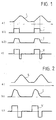
- FIGS. 1 and 2 of the accompanying drawings illustrate the typical procedures for driving an SRM in conditions of low speed of rotation ( Figure 1) and high speed of rotation ( Figure 2).
- the electrical time constant L/R becomes comparable to the energization time Ton of the said phase: since the phase must be de-energized even before the current has reached its rated value, it therefore becomes impossible to reach the desired mean current value (and therefore the desired torque level).
- Introduction of an energization advance in principle may be achieved by displacing the position sensors a few mechanical degrees forwards or backwards (in the opposite direction to the direction of rotation of the rotor).
- the sensors keyed onto the rotor in a permanent manner it is possible to achieve an optimum result only for a predefined and single advance value.
- the result is that an optimum current waveform is obtained only for predefined speeds, with a decrease in efficiency for the whole of the remainder of the motor-speed range.
- the patent US-A-5977740 discloses a control system which energizes in a selective manner the winding of a motor so as to maximize the efficiency and the output torque, taking into account possible variations in the speed of the rotor, the temperature of the windings and the power supply voltage. More specifically, this document describes a vehicle equipped with a motor in which the advance is controlled in order to brake the vehicle. Control of the advance is performed using a DSP and complex mathematical calculations.
- US-A-5942865 describes a solution in which the advance of a motor is controlled by means of analog circuitry. Besides the constructional complexity, this solution has the drawback that the advance may be set only manually using potentiometers.
- Document EP-A-O 802 622 after which the preamble of the annexed claim 1 is drafted, discloses a method for driving a brushless motor by calculating a frequency from a sensor signal and thus scanning a table in which waveform for a plum driving are stored.
- the object of the present invention is to provide a solution for the control of motors of the SRM type which is able to reconcile the need for low-cost and easily implemented solutions (for example using an 8-bit microcontroller) with the need for a sophisticated driving diagram (preferably using fuzzy-type logic systems).
- the invention proposes a solution providing an alternative to solutions which involve calculation of the phase energization instants. This is performed in a preferred manner by means of characterization of the advance values using fuzzy-logic models.
- the solution according to the invention allows control of the necessary phase energization advance in relation to the speed and load conditions of the motor.
- the solution according to the invention may be implemented in a particularly advantageous manner in three-phase motors which can be used, for example, in electric household appliances.
- the solution according to the invention is applicable to any number of phases and may be used in widely varying areas of application.
- the solution according to the invention is based on the use of fuzzy-type logic in order to provide an expert system capable of maximizing the electromechanical efficiency of the motor at every working point in the system.
- the solution according to the invention is based on three main factors, namely:
- the phase energization sequence by analysing the temporal relation between the information supplied by the sensors and the phase energization sequence, it is possible to isolate the minimum periodicity of the signals and discretize it into time windows or slots of the desired magnitude.
- the energization commands contained in each slot are memorized in the rows of a sequential-address look-up table.
- the sequential scanning of the table provides at its output the same original timing, provided that the scanning speed is correlated with the information supplied by at least one sensor.
- Figure 3 shows the typical progression of the signal S supplied by a sensor which detects the position of the rotor of an SRM.
- the signal S is shown in contrast with the ideal progression, in broken lines, of the phase inductance IF.
- the motor 10 being a three-phase SRM (6/4 poles) with one or more associated sensors 12 by means of which it is possible to obtain, for each sensor, four square waves for each rotation of the motor.
- a quarter of a rotation corresponds to the single period T of a sensor.
- the diagram according to Figure 3 relates to a solution where the phases have been excited individually, as represented by the differently hatched rectangles indicated by the references Iph1, Iph2 and Iph3, respectively.
- N time windows or slots (ranging from 0 to N-1), into which the period T of the signal S has been subdivided, is shown.
- the number N may be chosen as required, in accordance with the desired resolution of the advance.
- the table TA shown in Figure 4 is therefore organized in a corresponding number of rows (in the case in question 90 rows - see the column furthest to the right indicated by "slot"), with each row intended to be scanned for a time interval corresponding to a degree of rotation of the rotor. It is obvious, moreover, that the duration of this interval depends on the speed of the rotor.
- Each row in the table according to Figure 4 contains, for each column, the logic value of the command to be sent to a corresponding switch Sw1, Sw2, ..., Swn for energization of the motor phases. Thus, as will be more fully described below, these switches are included in the block 13 in Figure 8.
- the scanning period must be an exact submultiple (equal to N) of the period generated by the sensor in the preceding sector.
- the output sequence generated by means of the table TA has an overall duration equal to the period of the sensor (in the example equal to T).
- the scanning frequency of the table must be N.Fs.
- the problem may therefore be expressed in terms of the digital measurement of the period/frequency of the sensor.
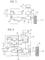
- the period of the signal S of the sensor (measured, for example, using a 16-bit counter) is provided as a signal Ts on the line 14.
- a frequency clock signal Fck generated by a respective clock (not shown) is present.
- the reference number 20 indicates a 16-bit counter with respect to which the signal Ts acts as a start/stop signal counting the clock signal present on the line 16.
- the digital value obtained by the counter 20 is used for parallel loading of another counter 22 also consisting preferably of another 16-bit counter.
- the clock frequency of the counter 22 is, however, N times greater, being obtained from the clock signal present on the line 16 by means of a multiplier by N, indicated by 24.
- the end-of-count signal Tstep of the counter 22 is sent on the line 26 to an address counter 28 which acts as a pointer in the table T.
- the reference number 30 indicates a module which provides the counter 28 with a suitable offset depending on a target advance (target pre-phase) value provided on the line 32 from a module M further described below.
- Figure 6 shows the internal architecture of the functional blocks shown in Figure 5.
- the translation into VHDL language envisages the use of 16-bit variables which are synthesized as counters.
- the diagram according to Figure 6 envisages that the period Ts of the signal S present on the line 14 is measured with a sampling time Tck (for example with a value of 50 microseconds).
- Tck for example with a value of 50 microseconds.
- This resolution allows reading of periods in a very wide range and may be varied depending on the characteristics of the motor.
- the value read is stored in a buffer register 20a, while a timer 20b performs subsequent measurement.
- the digital value obtained in the buffer 20a is used to load the counter 22 - in the form of a decremental counter - with a module which is the same as the first module, but which counts with a frequency N times greater. This greater speed causes resetting of the counter 22 in a relatively short time.
- the counter 22 produces an end-of-count pulse forming precisely the signal Tstep present on the line 26 and, at the same time, it is reloaded with the same previous value supplied by the buffer 20a.
- the signal Tstep is used in block 28 to synchronize the increment in the pointing variable which scans the table TA, normally realized in the form of a ROM.
- the digital value output by the block 20 assumes all the values from 0 to N-1 within a period of the sensor and therefore the table is entirely covered in the same time. Essentially, if the sensor period has been subdivided into 90 one-degree slots (as in a three-phase motor with three sensors), a table with 90 rows is obtained. 90 Tstep pulses and a counter in the block 28 which cyclically counts from 0 to 89 are thus needed in order to scan the table completely so as to reconstruct the theoretical energization timing.
- phase energization advance is simply converted into the offset value provided to the block 30 on the line 32 so as to be able to be added, in the block 28, to the value used for pointing in the table TA.
- the block 30 stores the desired energization advance value and supplies it to the block controlling the table pointer. Therefore, in the case of the advance being other than 0, the table TA is scanned from the location corresponding to the desired advance.
- Figure 4 shows schematically, in the form of arrows which point to successive rows in the table TA, various possible advance positions between the value 0° (0°_ant pointer) and the value 45° (45°_ant pointer).
- the pointer is initialized in the middle of the table from arrival of the edge of Ts and then incremented by each pulse Tstep. After 90 Tstep pulses, the pointer is again situated at the midway point of the table for the next cycle (a quarter of a rotation by the rotor).
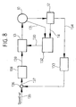
- phase energization function of the motor 10 is assigned to controlled power switches which are included, with regard to the diagram according to Figure 8, in the block 13 and are individually identifiable as Sw1, Sw2, ..., Swn. These are the same identification codes assigned to each of the vertical columns in the lefthand part of table T shown in Figure 4. In this part of the table, the presence of a "0" indicates that the respective power switch is deactivated, while the presence, in the table, of the value "1" indicates activation or energization of the corresponding switch.
- the different topologies used for the power stage 13 require flexibility of the control signals of the corresponding power switches, usually consisting of transistors. With the solution illustrated here it is possible to assign a column in the table TA to each transistor Sw1, Sw2, ..., Swn of the power stage 13 so as to obtain independent control of its energization.
- the most frequently used topology envisages four phase energization switches which are positioned at the bottom of the bridge and four for performing the function of chopping of the phase current, positioned at the top of the bridge.
- the table TA is constructed as a memory with 8-type parallel arrangement.
- a typical problem of SRMs is associated with the presence of the multiplexer 31. Although many position sensors may be fitted, when the rotor is at a standstill, at the moment of start-up it is not possible to know which will be the initial direction of rotation as soon as the appropriate phase is energized.
- a start-up routine which starts the rotor moving in the desired direction, is frequently incorporated in the microcontrollers which control the entire system.
- the multiplexer 31 basically forms a kind of block for bypassing the peripheral unit intended to allow direct control of the switches of the stage 13 by the microcontroller via corresponding lines ⁇ C_1, ⁇ C_2, ..., ⁇ C_n.
- the multiplexer is controlled by means of a line 310 so as to ensure that the switches 13 may be initially controlled, during start-up, by the signals supplied by the microcontroller (or by other external circuitry such as a cabled logic, manual commands, etc.). When the rotor has reached the desired speed, the operating condition is then switched to that in which control of the switches in the stage 13 is assigned to the signals obtained from the table TA.
- the lines driving the stage 13 are denoted collectively by the reference number 130.
- the reference number 131 denotes a line on which there is present a current signal received from the motor 10 and used for operations involving regulation of the advance phase, performed in the block 132, which obviously incorporates also the various elements shown in Figures 5 and 6.
- the reference number 133 indicates a block which receives, on the line 134, the output signal of at least one of the sensors of the block 12 so as to allow determination of the speed of rotation of the motor.
- the item of data relating to the speed of rotation of the motor is used in a feedback control loop intended to allow a reference speed defined on an input line 135 to be maintained by the motor 10.
- a difference node 136 generates, on the basis of the reference value present on the line 135 and the feedback value supplied by the block 133, a speed deviation or error signal which, supplied on a line 137 to a control block 138, allows this block to generate on a respective output line 139 a corresponding control signal (typically associated, for example, with the operating angle of the switches included in the block 13).
- the set of elements represented by the blocks 132, 133 and 138 may be realized using an 8-bit microcontroller with a fuzzy-calculation capacity combined with a programmable logic.
- Such a system may be used, for example, for the control of a three-phase variable reluctance motor with six stator poles and four rotor poles.
- a possible speed range which may be obtained varies from 100 to 20,000 revolutions per minute, while the energization advance may vary from 0 to 45 degrees.
- both the block 132 and the block 138 envisage the use of fuzzy-type logic systems.
- controller 138 may be advantageously constructed in the form of a PID (Proportional, Integral, Derivative) control system of the fuzzy type.
- PID Proportional, Integral, Derivative
- fuzzy model ensures, in particular as regards precision, results which are far better than those of alternative solutions such as, for example, mapping and interpolation of the data from a look-up table.
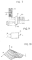
- Figures 9 and 10 illustrate in schematic form the implementation, in the module M, of the abovementioned fuzzy model obtained by means of algorithms of the neural type with network learning relating to the data measured on the motor.
- the fuzzy model is schematically shown in Figure 9, where it can be seen that the module M is able to obtain the optimum advance value ⁇ depending on the speed of rotation (represented here as the pulse ⁇ ) and the current value I (indicating the load of the motor).
- Figure 10 shows the fuzzy correlation between the input variables ⁇ and I and the output variable ⁇ .
- the constructional details and the embodiments may be varied with respect to that described and illustrated, without thereby departing from the scope of the present invention, as defined by the accompanying claims. This applies, in particular, to the possibility of realizing the system described both as a programmable logic and - in a currently preferred embodiment of the invention - entirely on silicon.
Landscapes
- Engineering & Computer Science (AREA)
- Power Engineering (AREA)
- Control Of Electric Motors In General (AREA)
Claims (17)
- Verfahren zum Steuem eines geschalteten Reluktanzmotors oder SRM (Switched Reluctance Motor) (10), das die folgenden Operationen aufweist:dadurch gekennzeichnet, dass es die folgenden Operationen aufweist:Detektieren (12) von Signalen (S), die die Winkelposition des Rotors des Motors (10) anzeigen, wobei die Signale vorgegebene Perioden (T) aufweisen, undVersorgen des Motors (10) mit Energie (13) in Abhängigkeit von den Signalen (S),Diskretisieren der Perioden (T) der Signale (S) in eine vorgegebene Anzahl (N) von Zeitfenstern,Definieren einer Tabelle (TA) mit einer Vielzahl von Positionen (0, ..., N-1), die jeweils einem der Zeitfenster entsprechen,Zuordnen zu jeder der Positionen der Tabelle (TA) eine jeweilige Konfiguration von Leistungsschaltern (Sw1, ..., Swn) zur Energieversorung des Motors, undzyklisches Abtasten der Positionen (0, ..., N-1) der Tabelle (TA) mit einer Abtastperiode, die durch die Diskretisierungsoperation bestimmt wird, mit einer vorgegebenen Anzahl (N) von Zeitfenstern, so dass die Abtastperiode ein genaues Unter-Vielfaches der. Perioden (T) der Signale ist, und Versorgen des Motors (10) mit einer Energieversorgungs-Konfiguration, die den Positionen zugeordnet wird, die in jedem Fall während der Abtastbewegung identifiziert wurden.
- Verfahren nach Anspruch 1, dadurch gekennzeichnet, dass die Positionen der Tabelle (TA) mit einer Frequenz abgetastet werden, die ein Mehrfaches (N) der Frequenz darstellt, die mit den vorgegebenen Perioden der Signale (S) assoziiert ist.
- Verfahren nach Anspruch 1 oder Anspruch 2, dadurch gekennzeichnet, dass es die Operation aufweist, die Tabelle (TA) aus einer Referenz-Position (α), die selektiv variabel abhängend von den Betriebsbedingungen des Motors ist, sequentiell abzutasten.
- Verfahren nach Anspruch 3, dadurch gekennzeichnet, dass die Referenz-Position (α) auf der Grundlage wenigstens eines Parameters ermittelt wird, der aus der aus der Rotationsgeschwindigkeit (ω) und der Last (I) des Motors bestehenden Gruppe ausgewählt wird.
- Verfahren nach Anspruch 3 oder Anspruch 4, dadurch gekennzeichnet, dass es die Operation des Ermittelns der Referenz-Position (α) unter Verwendung einer Fuzzy-Logik aufweist, wobei die Fuzzy-Logik ein Modell aufweist, das auf der Grundlage von optimalen Versuchsdaten einer Referenz-Position für verschiedene Werte von wenigstens einem Parameter aufgebaut ist, der aus der aus der Rotationsgeschwindigkeit (ω) und der Last (I) des Motors bestehenden Gruppe ausgewählt wird.
- Verfahren nach irgendeinem der vorhergehenden Ansprüche, dadurch gekennzeichnet, dass es die Operation des Energieversorgens des Motors auf alternative Weise aufweist, wobei die Energieversorgungs-Konfiguration verwendet wird, die mit der Position assoziiert ist, die in jedem Fall während der Bewegung identifiziert wird, die das Abtasten der Tabelle (TA) enthält, und wobei eine selektiv vorgegebenen Energieversorgungs-Konfiguration (µC_1, ..., µC_n) verwendet wird, um dem Motor (10) eine vorgegebene Rotationsrichtung zu verleihen.
- System zum Steuern eines geschalteten Reluktanzmotors oder SRM (Switched Reluctance Motor) (10) mittels Verwendens von Signalen (S), die die Winkelposition des Rotors des Motors (10) anzeigen, wobei die Signale (S) vorgegebene Perioden (T) aufweisen, der Motor (10) ein mit ihm verbundenes Energieversorgungs-Modul (13) aufweist, das abhängend von den Signalen (S) aktiviert werden kann, dadurch gekennzeichnet, dass es folgendes aufweist:eine Diskretisierungseinheit (20, 22) zum Diskretisieren der Perioden der Signale (S) in eine vorgegebene Anzahl (N) von Zeitfenstern,eine Tabelle (TA) mit einer Vielzahl von Positionen (0, ..., N-1), die jeweils einem der Zeitfenster entsprechen und mit diesen assoziiert eine jeweilige Konfiguration von Leistungsschaltern (Sw1, ..., Swn) zur Energieversorung des Motors (10) aufweisen, undein Abtast-Modul (28) zum zyklischen Abtasten der Positionen der Tabelle (TA) mit einer Abtastperiode, die durch die Diskretisierungsoperation bestimmt wird, mit einer vorgegebenen Anzahl (N) von Zeitfenstern, so dass die Abtastperiode ein genaues Unter-Vielfaches der Perioden (T) der Signale ist, und zum Aktivieren des Energieversorgungs-Moduls (13), wobei die Energieversorgungs-Konfiguration verwendet wird, die mit der Position assoziiert ist, die in jedem Fall durch Abtasten des Abtast-Moduls (28) innerhalb der Tabelle (TA) identifiziert wird.
- System nach Anspruch 7, dadurch gekennzeichnet, dass das Abtast-Modul (28) die Tabelle (TA) mit einer Frequenz abtastet, die ein Vielfaches der Frequenz ist, die durch die vorgegebenen Perioden der Signale (S) identifiziert wird.
- System nach Anspruch 8, dadurch gekennzeichnet, dass die Diskretisierungseinheit einen ersten Zähler (20), der das Signal (S) empfängt, das die Winkelposition des Motorrotors identifiziert, und einen zweiten Zähler (22) aufweist, der durch den ersten Zähler (20) angetrieben wird; wobei die Zählerfrequenz des zweiten Zählers (22) ein Vielfaches (N) der Zählerfrequenz des ersten Zählers (20) ist.
- System nach einem der Ansprüche 7 bis 9, dadurch gekennzeichnet, dass das Abtast-Modul (28) die Tabelle (TA) aus einer Referenz-Position (α), die selektiv variabel (30, 32) abhängend von den Betriebsbedingungen des Motors ist, sequentiell abtastet.
- System nach Anspruch 10, dadurch gekennzeichnet, dass es eine Einheit (M) zum Ermitteln der Referenz-Position (α) abhängend von wenigstens einem Parameter aufweist, der aus der aus der Rotationsgeschwindigkeit (ω) und der Last (I) des Motors bestehenden Gruppe ausgewählt wird.
- System nach Anspruch 11, dadurch gekennzeichnet, dass die Einheit (M) zum Ermitteln der Referenz-Position (α) mittels Verwendens einer Fuzzy-Logik arbeitet, wobei die Fuzzy-Logik ein Modell aufweist, das auf der Grundlage von optimalen Versuchsdaten einer Referenz-Position für verschiedene Werte von wenigstens einem Parameter aufgebaut ist, der aus der aus der Rotationsgeschwindigkeit (ω) und der Last (I) des Motors bestehenden Gruppe ausgewählt wird.
- System nach einem der Ansprüche 7 bis 12, dadurch gekennzeichnet, dass es eine Auswähleinheit (31) aufweist, die mit dem Energieversorgungs-Modul (13) des Motors (10) assoziiert ist und selektiv (310) zwischen einem ersten Betriebszustand, in welchem das Energieversorgungs-Modul (13) in Entsprechung zu Konfigurationen aktiviert ist, die mit den Positionen der Tabelle (TA) assoziiert sind, und wenigstens einem zweiten Betriebszustand geschaltet werden kann, in welchem das Energieversorgungs-Modul mit selektiv vorgegebenen Energieversorgungs-Konfigurationen (µC_1, ..., µC_n) aktiviert ist, so dass dem Motor (10) eine vorgegebenen Rotationsrichtung verliehen wird.
- System nach einem der Ansprüche 7 bis 13, dadurch gekennzeichnet, dass die Tabelle (TA) in Form eines Speichers, wie beispielsweise einem ROM, aufgebaut ist.
- System nach einem der Ansprüche 7 bis 14, dadurch gekennzeichnet, dass es auch eine Regelschleife (133 bis 139) aufweist, die in der Lage ist, das Energieversorgungs-Modul (13) des Motors (10) abhängend von einem Geschwindigkeitssignal zu regulieren, das von den Positions-Signalen (S) des Rotors abgeleitet wird, so dass die Rotationsgeschwindigkeit des Motors (10) bei einem vorgegebenen Referenzwert (135) gehalten wird.
- System nach Anspruch 15, dadurch gekennzeichnet, dass die Regelschleife ein Modul der Fuzzy-Art, wie beispielsweise ein PID-Regelsystem, aufweist.
- System nach einem der Ansprüche 7 bis 16, das insgesamt mit Silizium realisiert wird.
Priority Applications (3)
| Application Number | Priority Date | Filing Date | Title |
|---|---|---|---|
| DE60024418T DE60024418D1 (de) | 2000-05-26 | 2000-05-26 | Verfahren und Vorrichtung zur Steuerung von Reluktanzmotoren |
| EP00830379A EP1158657B1 (de) | 2000-05-26 | 2000-05-26 | Verfahren und Vorrichtung zur Steuerung von Reluktanzmotoren |
| US09/866,534 US6509710B2 (en) | 2000-05-26 | 2001-05-25 | Method and system for driving switched reluctance motors (SRM) |
Applications Claiming Priority (1)
| Application Number | Priority Date | Filing Date | Title |
|---|---|---|---|
| EP00830379A EP1158657B1 (de) | 2000-05-26 | 2000-05-26 | Verfahren und Vorrichtung zur Steuerung von Reluktanzmotoren |
Publications (2)
| Publication Number | Publication Date |
|---|---|
| EP1158657A1 EP1158657A1 (de) | 2001-11-28 |
| EP1158657B1 true EP1158657B1 (de) | 2005-11-30 |
Family
ID=8175345
Family Applications (1)
| Application Number | Title | Priority Date | Filing Date |
|---|---|---|---|
| EP00830379A Expired - Lifetime EP1158657B1 (de) | 2000-05-26 | 2000-05-26 | Verfahren und Vorrichtung zur Steuerung von Reluktanzmotoren |
Country Status (3)
| Country | Link |
|---|---|
| US (1) | US6509710B2 (de) |
| EP (1) | EP1158657B1 (de) |
| DE (1) | DE60024418D1 (de) |
Families Citing this family (11)
| Publication number | Priority date | Publication date | Assignee | Title |
|---|---|---|---|---|
| EP1256164A2 (de) * | 2000-02-09 | 2002-11-13 | Dana Corporation | Steuerungsverfahren für einen reluktanzgenerator |
| US7250734B1 (en) * | 2003-05-27 | 2007-07-31 | Synchrony, Inc. | High performance switched reluctance machine |
| KR100602800B1 (ko) * | 2003-12-10 | 2006-07-20 | 안진우 | 아날로그 엔코더장치에 의한 에스알엠의 정밀 각도 제어방법 |
| KR100713776B1 (ko) * | 2005-10-04 | 2007-05-02 | 에스알텍 주식회사 | 검출 전류의 비교를 통한 에스알엠의 여자 위치 검출 방법및 장치 |
| US7973503B2 (en) * | 2007-06-26 | 2011-07-05 | Wooward HRT, Inc. | Motor system employing analog encoded hall effect sensor position information for reduced wiring |
| WO2009026690A2 (en) | 2007-08-24 | 2009-03-05 | Sunco Investments Ltd. | Multistage variable reluctance motor/generator |
| US20090058330A1 (en) * | 2007-08-30 | 2009-03-05 | Seagate Technology Llc | Driving a multi-phased motor |
| CN105099323A (zh) * | 2015-08-06 | 2015-11-25 | 中国矿业大学(北京) | 一种基于模糊控制的嵌入式电磁调速采煤机牵引系统 |
| JP2018191419A (ja) * | 2017-05-01 | 2018-11-29 | 日本電産株式会社 | ブラシレスdcモータ、ブラシレスdcモータの種類を識別する識別方法および識別装置 |
| CN108258956B (zh) * | 2018-01-09 | 2020-05-19 | 南京邮电大学 | 一种单绕组宽转子齿结构无轴承开关磁阻发电机控制方法 |
| CN109412492B (zh) * | 2018-11-27 | 2020-10-30 | 中国地质大学(武汉) | 基于模糊等价输入干扰法的速度环控制参数自整定方法 |
Family Cites Families (15)
| Publication number | Priority date | Publication date | Assignee | Title |
|---|---|---|---|---|
| JPS52122733A (en) * | 1976-04-07 | 1977-10-15 | Toshiba Corp | Pulse line converter |
| US4739240A (en) * | 1987-04-29 | 1988-04-19 | General Electric Company | Commutator for switched reluctance drive |
| US5168202A (en) * | 1991-08-30 | 1992-12-01 | Platt Saco Lowell Corporation | Microprocessor control of electric motors |
| US5589746A (en) * | 1994-11-10 | 1996-12-31 | Seagate Technology, Inc. | Brushless motor speed control arrangement having derived common mode supply signal component |
| JP3564582B2 (ja) * | 1994-12-16 | 2004-09-15 | アイシン精機株式会社 | スイッチドレラクタンスモ−タの通電制御装置 |
| US5637974A (en) | 1995-04-21 | 1997-06-10 | Itt Automotive Electrical Systems, Inc. | Method and apparatus for hybrid direct-indirect control of a switched reluctance motor |
| GB9523256D0 (en) * | 1995-11-14 | 1996-01-17 | Switched Reluctance Drives Ltd | Phase energization controller and method for controlling switched reluctance machines using simple angular position sensors with improved angle interpolation |
| GB9525952D0 (en) | 1995-12-19 | 1996-02-21 | Switched Reluctance Drives Ltd | Sensorless rotor position monitoring in reluctance machines |
| DE69605019T2 (de) * | 1996-03-29 | 2000-02-24 | Stmicroelectronics S.R.L., Agrate Brianza | Vorbestimmte und in einem Festwertspeicher gespeicherte Antriebsströme anwendendes Antriebssystem für einen bürstenlosen Motor |
| GB9607688D0 (en) * | 1996-04-12 | 1996-06-12 | Switched Reluctance Drives Ltd | Current shaping in reluctance machines |
| JP3700305B2 (ja) * | 1996-04-19 | 2005-09-28 | 松下電器産業株式会社 | ブラシレスモータの駆動装置とモータのロータ位置検出装置 |
| KR100210080B1 (ko) | 1996-11-01 | 1999-07-15 | 윤종용 | 스위치드 릴럭턴스 모터의 구동 제어 장치 |
| US5977740A (en) | 1997-05-14 | 1999-11-02 | Itt Manufacturing Enterprises, Inc. | Brake-by-wire system with switched reluctance motor controller |
| JP2000287488A (ja) * | 1999-03-31 | 2000-10-13 | Aisin Seiki Co Ltd | 電気モータの通電制御装置 |
| DE19961798C2 (de) * | 1999-12-22 | 2001-11-15 | Daimler Chrysler Ag | Verfahren und Anordnung zur Regelung des Stroms in einer geschalteten Reluktanzmaschine |
-
2000
- 2000-05-26 DE DE60024418T patent/DE60024418D1/de not_active Expired - Lifetime
- 2000-05-26 EP EP00830379A patent/EP1158657B1/de not_active Expired - Lifetime
-
2001
- 2001-05-25 US US09/866,534 patent/US6509710B2/en not_active Expired - Lifetime
Also Published As
| Publication number | Publication date |
|---|---|
| US6509710B2 (en) | 2003-01-21 |
| EP1158657A1 (de) | 2001-11-28 |
| DE60024418D1 (de) | 2006-01-05 |
| US20020021103A1 (en) | 2002-02-21 |
Similar Documents
| Publication | Publication Date | Title |
|---|---|---|
| JP2586918B2 (ja) | 励磁切換式リラクタンスモータの作動方法及び制御装置 | |
| EP0573198B1 (de) | Sensorlose Rotorlagemessung in elektrischen Maschinen | |
| US5990643A (en) | Sensorless commutation position detection for brushless D.C. motors | |
| US4961038A (en) | Torque estimator for switched reluctance machines | |
| US5703449A (en) | Controller for brushless DC motor without position sensor | |
| CN107257214B (zh) | 电机的控制 | |
| EP0316077B1 (de) | Bürstenloser Motor | |
| EP3665770B1 (de) | Verfahren und system zur steuerung einer geschalteten reluktanzmaschine | |
| US6509710B2 (en) | Method and system for driving switched reluctance motors (SRM) | |
| EP3080907B1 (de) | Motorspule ansteuerverfahren | |
| EP1109307A2 (de) | Regelung für eine bürstenlose Maschine | |
| US5627441A (en) | Apparatus for controlling motor drive and method for controlling thereof | |
| KR100720323B1 (ko) | 스위치드 릴럭턴스 머신의 회전자 위치 검출 방법 및 릴럭턴스 구동 시스템 | |
| EP0774828A1 (de) | Steuerung der Phasenversorgung und Verfahren zur Steuerung von geschalteten Reluktanzmaschinen mit Winkelstellungssensoren und Winkelinterpolation | |
| US20060110140A1 (en) | Method and apparatus for controlling motor drive | |
| JP3541861B2 (ja) | Dcブラシレスモータ | |
| US20040108826A1 (en) | Method for characterizing a rotating electromagnetic machine | |
| JPH09154294A (ja) | ブラシレス直流モータの駆動方法 | |
| JPH0823695A (ja) | モータの制御方法 | |
| CN1945960B (zh) | 电机中的转子位置检测 | |
| JPH06253584A (ja) | センサレスブラシレスモータの駆動装置 | |
| JP2728311B2 (ja) | Dcブラシレスモータのモータ制御装置 | |
| JPH07255193A (ja) | ブラシレスモータの制御方法およびその装置 | |
| JP2679879B2 (ja) | ブラシレスモータの速度制御装置 | |
| JP2002335687A (ja) | 電気モータの通電制御装置 |
Legal Events
| Date | Code | Title | Description |
|---|---|---|---|
| PUAI | Public reference made under article 153(3) epc to a published international application that has entered the european phase |
Free format text: ORIGINAL CODE: 0009012 |
|
| AK | Designated contracting states |
Kind code of ref document: A1 Designated state(s): DE FR GB IT Kind code of ref document: A1 Designated state(s): AT BE CH CY DE DK ES FI FR GB GR IE IT LI LU MC NL PT SE |
|
| AX | Request for extension of the european patent |
Free format text: AL;LT;LV;MK;RO;SI |
|
| 17P | Request for examination filed |
Effective date: 20020218 |
|
| AKX | Designation fees paid |
Free format text: DE FR GB IT |
|
| 17Q | First examination report despatched |
Effective date: 20040611 |
|
| GRAP | Despatch of communication of intention to grant a patent |
Free format text: ORIGINAL CODE: EPIDOSNIGR1 |
|
| GRAS | Grant fee paid |
Free format text: ORIGINAL CODE: EPIDOSNIGR3 |
|
| GRAA | (expected) grant |
Free format text: ORIGINAL CODE: 0009210 |
|
| AK | Designated contracting states |
Kind code of ref document: B1 Designated state(s): DE FR GB IT |
|
| REG | Reference to a national code |
Ref country code: GB Ref legal event code: FG4D |
|
| REF | Corresponds to: |
Ref document number: 60024418 Country of ref document: DE Date of ref document: 20060105 Kind code of ref document: P |
|
| PG25 | Lapsed in a contracting state [announced via postgrant information from national office to epo] |
Ref country code: DE Free format text: LAPSE BECAUSE OF FAILURE TO SUBMIT A TRANSLATION OF THE DESCRIPTION OR TO PAY THE FEE WITHIN THE PRESCRIBED TIME-LIMIT Effective date: 20060301 |
|
| PG25 | Lapsed in a contracting state [announced via postgrant information from national office to epo] |
Ref country code: GB Free format text: LAPSE BECAUSE OF NON-PAYMENT OF DUE FEES Effective date: 20060526 |
|
| ET | Fr: translation filed | ||
| PLBE | No opposition filed within time limit |
Free format text: ORIGINAL CODE: 0009261 |
|
| STAA | Information on the status of an ep patent application or granted ep patent |
Free format text: STATUS: NO OPPOSITION FILED WITHIN TIME LIMIT |
|
| 26N | No opposition filed |
Effective date: 20060831 |
|
| GBPC | Gb: european patent ceased through non-payment of renewal fee |
Effective date: 20060526 |
|
| PGFP | Annual fee paid to national office [announced via postgrant information from national office to epo] |
Ref country code: IT Payment date: 20070524 Year of fee payment: 8 |
|
| PGFP | Annual fee paid to national office [announced via postgrant information from national office to epo] |
Ref country code: FR Payment date: 20070529 Year of fee payment: 8 |
|
| REG | Reference to a national code |
Ref country code: FR Ref legal event code: ST Effective date: 20090119 |
|
| PG25 | Lapsed in a contracting state [announced via postgrant information from national office to epo] |
Ref country code: FR Free format text: LAPSE BECAUSE OF NON-PAYMENT OF DUE FEES Effective date: 20080602 |
|
| PG25 | Lapsed in a contracting state [announced via postgrant information from national office to epo] |
Ref country code: IT Free format text: LAPSE BECAUSE OF NON-PAYMENT OF DUE FEES Effective date: 20080526 |