EP1160132A2 - Structure de bobine de cable - Google Patents
Structure de bobine de cable Download PDFInfo
- Publication number
- EP1160132A2 EP1160132A2 EP01401397A EP01401397A EP1160132A2 EP 1160132 A2 EP1160132 A2 EP 1160132A2 EP 01401397 A EP01401397 A EP 01401397A EP 01401397 A EP01401397 A EP 01401397A EP 1160132 A2 EP1160132 A2 EP 1160132A2
- Authority
- EP
- European Patent Office
- Prior art keywords
- cable
- enclosure
- flat
- guide
- reverse path
- Prior art date
- Legal status (The legal status is an assumption and is not a legal conclusion. Google has not performed a legal analysis and makes no representation as to the accuracy of the status listed.)
- Withdrawn
Links
- 230000000295 complement effect Effects 0.000 claims description 8
- 238000004804 winding Methods 0.000 claims description 5
- 238000005192 partition Methods 0.000 claims description 3
- 238000000638 solvent extraction Methods 0.000 claims description 2
- 239000004020 conductor Substances 0.000 description 2
- 238000010276 construction Methods 0.000 description 1
- 238000004519 manufacturing process Methods 0.000 description 1
- 239000000463 material Substances 0.000 description 1
- 230000000630 rising effect Effects 0.000 description 1
Images






Classifications
-
- B—PERFORMING OPERATIONS; TRANSPORTING
- B60—VEHICLES IN GENERAL
- B60R—VEHICLES, VEHICLE FITTINGS, OR VEHICLE PARTS, NOT OTHERWISE PROVIDED FOR
- B60R16/00—Electric or fluid circuits specially adapted for vehicles and not otherwise provided for; Arrangement of elements of electric or fluid circuits specially adapted for vehicles and not otherwise provided for
- B60R16/02—Electric or fluid circuits specially adapted for vehicles and not otherwise provided for; Arrangement of elements of electric or fluid circuits specially adapted for vehicles and not otherwise provided for electric constitutive elements
- B60R16/023—Electric or fluid circuits specially adapted for vehicles and not otherwise provided for; Arrangement of elements of electric or fluid circuits specially adapted for vehicles and not otherwise provided for electric constitutive elements for transmission of signals between vehicle parts or subsystems
- B60R16/027—Electric or fluid circuits specially adapted for vehicles and not otherwise provided for; Arrangement of elements of electric or fluid circuits specially adapted for vehicles and not otherwise provided for electric constitutive elements for transmission of signals between vehicle parts or subsystems between relatively movable parts of the vehicle, e.g. between steering wheel and column
Definitions
- the present invention generally pertains to a cable reel structure incorporated into a steering system of a vehicle e.g. an automobile.
- the cable reel structure of the invention is defined by a fixed member and a mobile member, and a cable enclosure formed between them.
- the cable enclosure of the invention contains a cable guide having e.g. a ring-shape with at least one cut-out portion, which partitions the cable enclosure into an inner cable enclosure and an outer cable enclosure along the radial direction of the cable reel structure.
- the cable enclosure further comprises a flat cable, which is spiraled in the inner cable enclosure in a first circular direction, U-turned around the cut-out portion of the cable guide, and then spiraled in the outer cable enclosure in a second circular direction reversed with respect to the first circular direction.
- Such a structural configuration allows the cable reel structure to be mounted more efficiently than in the case of the prior art.
- the fixed member of the cable reel structure forms an outer cylindrical wall and top guard of the cable reel, and is immobilized with a combination switch body, which is in turn fixed with a steering column.
- the mobile member forms an inner cylindrical wall and bottom guard of the cable reel, and is fixed with the steering wheel.
- the mobile member is then mounted with the fixed member in a freely rotatable way, thereby forming a substantially torus-shaped enclosure, in which a spiraled flat cable is stored.
- One end of the flat cable is connected to the fixed member, and the other end is connected to the mobile member, so that an electrical current flow in the flat cable can be led out from the cable reel to external circuits.
- the mobile member is rotated clockwise or counter-clockwise in conjunction with the movement of the steering wheel, and the spiraled flat cable is wound or unwound accordingly.
- the prior art cable reel comprises a torus-shaped enclosure 3 formed by a fixed member 1 and a mobile member 2.
- the torus-shaped enclosure 3 then contains a cable guide 4 with a reverse path channel 4a (forming a C shape), thereby defining radially inner and outer enclosures.
- a flat cable 5 is first spiraled in the inner enclosure formed between the inner cylindrical wall of mobile member 2 and the cable guide 4, U-turned after being passed through the reverse path channel 4a, and then spiraled in the reverse direction in the outer enclosure formed between the cable guide 4 and the outer cylindrical wall of fixed member 1
- the flat cable 5 when the steering wheel is rotated e.g. clockwise, the flat cable 5 is led from the outer enclosure into the inner enclosure by making a U-turn at the reverse path channel 4a of the cable guide 4, and wound around the inner cylindrical wall of the mobile member 2.
- the flat cable 5 makes a reverse movement, i.e. the flat cable 5 is led into the outer enclosure of the cable reel, and added to the spirals in the outer enclosure from inside.
- the reverse-type flat cable can have a shorter length. Normally, at least the length equivalent to the part of flat cable inversely turned at the exit of the reverse path channel can be shortened. The length of the flat cable can thus be reduced to at least half the length in the normally spiraled case.
- the winding direction of the flat cable must be reversed between the outer enclosure and the inner enclosure when it is passed through the reverse path channel 4a of the cable guide 4.
- the reverse path channel 4a is oriented in the radial direction of the cable guide 4 as shown in Fig. 1B. Accordingly, for the flat cable to be brought through the reverse path channel 4a, the cable guide 4 must be mounted into the cable reel from the top thereof (Fig.1B).
- the flat cable tends to abut against edges 4b and 4c of the cable guide 4.
- the flat cable 5 is made of a flexible material and is mechanically vulnerable, such an abutment often damages the flat cable.
- the present invention has been contemplated to solve such problems. It provides a reversed-type cable reel, for which the structure is configured such that a cable guide can be fitted with a flat cable without causing damage to the latter.
- a reverse-type cable reel structure adapted to contain at least one flat cable and comprising a cable guide with at least one reverse path channel, the cable guide partitioning the cable reel structure into a radially inner enclosure and a radially outer enclosure.
- the flat cable(s) is/are first wound in said radially inner enclosure in a given winding direction, passed through the reverse path channel(s), inversely turned at the exit thereof, and wound in the radially outer enclosure in a direction reverse to the given winding direction.
- the cable guide is then divided into at least first and second complementary guide portions, thereby forming at least first and second reverse path channels, such that the complementary guide portions can be mounted laterally over the flat cable(s) after the latter has/have been wound in the radially inner enclosure.
- the cable reel structure comprises a fixed member including an outer cylindrical wall, and a mobile member including an inner cylindrical wall, mounted into the fixed member in a freely rotatable way, thereby defining a cable enclosure having a torus-shaped hollow portion, the cable enclosure contains the cable guide having a ring shape, the cable guide partitions the cable enclosure into the radially inner and external enclosures communicating therebetween through the reverse path channel(s), and the flat cable(s) has/have a first end portion fixed to the mobile member and a second end portion fixed to the fixed member, so that the first and second end portions of the flat cable(s) can be connected to external circuits.
- the reverse-type cable reel structure comprises at least two flat cables, and the latter are passed through the respective at least first and second reverse path channels.
- the at least two flat cables are fixed at different positions of the mobile member, so that the mobile member comprises at least two loci connecting to the external circuits.
- the first reverse path channel can be closed off.
- only one flat cable is used.
- the cable guide is formed into the shape of C, and the slit portion in C-shape serves as the point where the flat cable is turned to a reverse direction.
- the cable guide is divided into guide portions (subdivisions).
- the flat cable is first wound around the inner cylindrical wall of the mobile member.
- the guide portions are then mounted onto the flat cable from sideways of the cable reel, instead of from above as practiced in the past.
- the flat cable can thus be passed through the reverse path channel(s) without difficulty.
- the flat cable is no longer inserted from above into the reverse path channel formed in the cable guide. Accordingly, the flat cable is not subjected to deformation or damage.
- the flat cable and the cable guide can be assembled in a more restricted space than in the past.
- two guide portions are prepared so as to form two reverse path channels.
- Two flat cables are then prepared and passed through the respective reverse path channels.
- each of the two flat cables is first wound in the radially inner enclosure, and then wound inversely in the radially outer enclosure.
- the guide portions can be mounted so as to form a single reverse path channel.
- the structure then resembles the C-shaped cable guide of the prior art, and only one flat cable is used.
- the use of a reverse-type cable reel allows to shorten the length of each flat cable. For this reason, a greater number of circuits can now be connected to a flat cable.
- the cable reel structure of the present invention is well adapted to such circumstances, and is suitable for miniaturizing the entire cable reel structure.
- a mobile member 10 i.e. a rotor comprises an inner cylindrical wall 10a and a mobile guard portion 10b projecting therefrom in a radial direction.
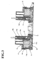
- a fixed member 11 i.e. a stator comprises a fixed guard portion 11a (Fig.3) and an outer cylindrical wall 11b rising therefrom.
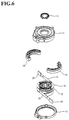
- first and second flat cables 12 and 13 a cable guide divided into first and second guide portions 14 and 15, which respectively have a complementary half torus shape, a guide base 16 having a substantially disk-like shape, a mobile member cover 17, and a locking ring 18 for fixing the mobile member 10 to a steering shaft.
- the mobile member 10 comprises an inner cylindrical wall and a top guard, whilst the fixed member 11 comprises an outer cylindrical wall and a bottom guard.
- the mobile member 10 is mounted onto the fixed member 11 in a freely rotatable way, so as to provide a cable enclosure 20 having a torus shape.
- the cable enclosure 20 is then made to contain first and second guide portions 14 and 15. Accordingly, when the first and second guide portions 14 and 15 are fitted into the cable reel structure, the guide portions 14 and 15 define a radially inner enclosure C1 together with the inner cylindrical wall of the mobile member 10, and a radially outer enclosure C2 together with the outer cylindrical wall of the fixed member 11 (see Fig.4).
- first and second guide portions 14 and 15 form first and second reverse path channels 21 and 22.
- the radially inner enclosure C1 contains first and second flat cables respectively designated 12 and 13 in a given spiraled state. They are then passed respectively through the corresponding reverse path channels 21 and 22, from the radially inner enclosure C1 into the radially outer enclosure C2, then U-turned, and spiraled in the radially outer enclosure C2 in a direction opposite to that of the spiral direction in the radially inner enclosure C1.
- a first end of each of the flat cables 12 and 13 is embedded in a first adapter case 24 or 25, in which the conductor elements of each of the flat cables are welded to corresponding bus bars and molded.
- the first adapter cases 24 and 25 are fitted into corresponding first slots 10c and 10d, which are provided in radially inner side of the inner cylindrical wall 10a of the mobile member 10 at substantially opposed positions.
- a second end of each of the flat cables 12 and 13 is embedded in a second adapter case 26 or 27, in which the conductor elements of each of the flat cables are welded to corresponding bus bars and molded such as to yield bared bus bar tips.
- the second adapter cases 26 and 27 are fitted with protrusions which are provided on the outer cylindrical wall 11b of the fixed member 11. The bared bus bar tips can thus be connected to external electrical cables.
- the first and second guide portions 14 and 15 have respectively complementary half torus shapes, so that, when combined, they form a torus-like body with two respective dividing edges.
- One dividing edge of the first guide portion 14 is configured into a protruding arch shape 14a, around which the first flat cable is turned.
- the corresponding dividing edge of the second guide portion 15, placed on the other side of the reverse path channel 21 is configured into a complementary recessed arch shape 15a.
- the other dividing edge of the first guide portion 14 is configured into a recessing arch shape 14b.
- the corresponding dividing edge of the second guide portion 15, placed on the other side of the reverse path channel 22 is configured into a complementary protruding arch shape 15b, around which the second flat cable is turned.
- the first and second guide portions 14 and 15 comprise respectively inner and outer semicircular faces and top and bottom arched faces.
- the respective inner semicircular faces are then provided with corresponding semicircular grooves 14c and 15c extending therealong and joining the respective outer semicircular faces (see Fig.2).
- the respective top arched faces are also provided with corresponding crossing recesses 14d and 15d (Fig.2), so that the latter can be fitted with protrusions 16a formed on the guide base 16.
- the respective inner semicircular faces of the first and second guide portions 14 and 15 are provided with linear ribs 14e and 15e which are aligned along an axial direction thereof at a given circumferential interval.
- the guide base 16 is mounted into the mobile member 10, so that the inner circular face of the guide base 16 fits around the inner cylindrical wall 10a of the mobile member 10.
- the flat cables 12 and 13 are flanked by the guide base 16 and the mobile guard.
- the first and second guide portions 14 and 15 are mounted laterally around the flat cables 12 and 13, so as to contain the latter 12 and 13 along the inner cylindrical wall 10a of the mobile member 10.
- the reverse path channels 21 and 22 are formed between the first and second guide portions 14 and 15, and through these channels 21 and 22 are drawn out the corresponding first and second flat cables 12 and 13.
- the first and second flat cables 12 and 13 are drawn out from the respective reverse path channels 21 and 22, and turned around the outer semicircular faces of the first and second guide portions 14 and 15 in the same direction (counter-clockwise in Fig.7).
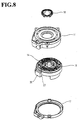
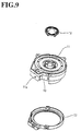
- the fixed member 11 is then mounted as shown consecutively in Figs.8 and 9, and the cover 17 and the locking ring 18 are mounted as shown consecutively in Figs.9 and 10. Thereafter, the assembled structure is turned upside down to obtain a cable reel structure of the invention shown in Fig.11.
- a cable guide is divided into two semicircular guide portions 14 and 15, and mounted laterally around flat cables 12 and 13, which are in turn wound around a mobile member 11.
- the semicircular guide portions 14 and 15 thus form reverse path channels 21 and 22, through which the flat cables 12 and 13 are passed and U-turned.
- the flat cables are no longer inserted from above a cable guide into reverse path channels formed therein, as has been practiced in the past. Accordingly, there is no risk of deforming or damaging the flat cables.
- assembly operations are made easier and better adapted to assemblage automation.
- two flat cables are drawn out through corresponding reverse path channels provided between a pair of divided cable guide portions, and U-turned at the exits of the reverse path channels.
- the divided guide portions may include one end closed and the other end opened, so that the cable guide forms only one reverse path channel, and one flat cable is used.
- the reverse-type cable reel structure of the invention comprises divided cable guides, which form reverse path channels.
- Each of the flat cables is wound in a given direction in a zone between the mobile member and the cable guide, passed through a reverse path channel, and then turned around towards the reverse direction in a zone between the cable guide and the fixed member.
- the divided cable guides are mounted around the flat cables from sideways. The flat cables are thus no longer fitted into the reverse path channels from above the cable guide, thereby avoiding damage or deformation of the flat cables.
Landscapes
- Engineering & Computer Science (AREA)
- Mechanical Engineering (AREA)
- Electric Cable Arrangement Between Relatively Moving Parts (AREA)
- Steering Controls (AREA)
- Storing, Repeated Paying-Out, And Re-Storing Of Elongated Articles (AREA)
Applications Claiming Priority (2)
| Application Number | Priority Date | Filing Date | Title |
|---|---|---|---|
| JP2000160832 | 2000-05-30 | ||
| JP2000160832A JP2001341945A (ja) | 2000-05-30 | 2000-05-30 | ケーブルリール |
Publications (2)
| Publication Number | Publication Date |
|---|---|
| EP1160132A2 true EP1160132A2 (fr) | 2001-12-05 |
| EP1160132A3 EP1160132A3 (fr) | 2003-07-30 |
Family
ID=18664961
Family Applications (1)
| Application Number | Title | Priority Date | Filing Date |
|---|---|---|---|
| EP01401397A Withdrawn EP1160132A3 (fr) | 2000-05-30 | 2001-05-29 | Structure de bobine de cable |
Country Status (3)
| Country | Link |
|---|---|
| US (1) | US6494396B2 (fr) |
| EP (1) | EP1160132A3 (fr) |
| JP (1) | JP2001341945A (fr) |
Cited By (2)
| Publication number | Priority date | Publication date | Assignee | Title |
|---|---|---|---|---|
| EP1357646A3 (fr) * | 2002-04-26 | 2005-01-19 | Toyoda Koki Kabushiki Kaisha | Dispositif à câble en forme de spirale |
| EP3803154B1 (fr) * | 2018-06-05 | 2022-10-12 | Bentec GmbH Drilling & Oilfield Systems | Câble chaîne |
Families Citing this family (26)
| Publication number | Priority date | Publication date | Assignee | Title |
|---|---|---|---|---|
| EP1790533B1 (fr) * | 2005-11-26 | 2008-05-28 | Delphi Technologies, Inc. | Dispositif de connexion situé entre le volant et la colonne de direction d'un véhicule |
| JP4152414B2 (ja) * | 2006-02-09 | 2008-09-17 | 矢崎総業株式会社 | 回転コネクタ装置 |
| DE102006013434A1 (de) * | 2006-03-14 | 2007-09-20 | Valeo Schalter Und Sensoren Gmbh | Verbindungsvorrichtung zur Übertragung von elektrischem Strom, insbesondere für eine Lenkradheizung eines Fahrzeugs |
| JP2008021555A (ja) * | 2006-07-13 | 2008-01-31 | Alps Electric Co Ltd | 回転コネクタ |
| US7400814B1 (en) | 2007-01-13 | 2008-07-15 | Furukawa Electric North America, Inc. | Wall-mountable optical fiber and cable management apparatus |
| US7715679B2 (en) * | 2007-05-07 | 2010-05-11 | Adc Telecommunications, Inc. | Fiber optic enclosure with external cable spool |
| US7756379B2 (en) | 2007-08-06 | 2010-07-13 | Adc Telecommunications, Inc. | Fiber optic enclosure with internal cable spool |
| US7869682B2 (en) | 2007-09-05 | 2011-01-11 | Adc Telecommunications, Inc. | Fiber optic enclosure with tear-away spool |
| US8265447B2 (en) | 2008-09-16 | 2012-09-11 | Adc Telecommunications, Inc. | Modular fiber optic enclosure with external cable spool |
| US8422847B2 (en) | 2009-07-21 | 2013-04-16 | Adc Telecommunications, Inc. | Rapid universal rack mount enclosure |
| WO2011107144A1 (fr) * | 2010-03-02 | 2011-09-09 | Abb Research Ltd | Système pour connecter électriquement un outil à un poignet de robot, et procédé pour cette opération |
| JP5117529B2 (ja) * | 2010-03-30 | 2013-01-16 | 古河電気工業株式会社 | 回転コネクタ装置 |
| US8837940B2 (en) | 2010-04-14 | 2014-09-16 | Adc Telecommunications, Inc. | Methods and systems for distributing fiber optic telecommunication services to local areas and for supporting distributed antenna systems |
| DE102010022542A1 (de) * | 2010-06-02 | 2011-12-08 | Leopold Kostal Gmbh & Co. Kg | Wickelfederkassette |
| RU2554300C2 (ru) | 2010-06-18 | 2015-06-27 | Адс Коммьюникейшнз (Шанхай) Ко., Лтд. | Волоконно-оптический терминал распределительной сети и способ разворачивания волоконного распределительного кабеля |
| CN105807379B (zh) | 2010-06-23 | 2019-06-18 | Adc电信公司 | 电信组件 |
| KR101322593B1 (ko) * | 2011-03-14 | 2013-10-28 | 알프스 덴키 가부시키가이샤 | 회전 커넥터 |
| US9717873B2 (en) * | 2011-05-20 | 2017-08-01 | Koninklijke Philips N.V. | Rotating electrical connector ADN respiratory gas delivery system employing same |
| WO2012178070A2 (fr) | 2011-06-24 | 2012-12-27 | Adc Telecommunications, Inc. | Boîtier de dispositif de connexion en fibres doté d'ensembles plaque modulaires |
| US9188760B2 (en) | 2011-12-22 | 2015-11-17 | Adc Telecommunications, Inc. | Mini rapid delivery spool |
| US10031305B2 (en) | 2012-12-19 | 2018-07-24 | CommScope Connectivity Belgium BVBA | Distribution device with incrementally added splitters |
| DE102015118543A1 (de) * | 2015-10-29 | 2017-05-04 | Valeo Schalter Und Sensoren Gmbh | Schutzabdeckung für ein Wickelfedergehäuse, Wickelfedergehäuseanordnung und Fahrzeug mit einer solchen Wickelfedergehäuseanordnung |
| AU2017217525A1 (en) * | 2016-02-08 | 2018-07-05 | Commscope Technologies Llc | Fiber demarcation point and slack storage |
| CN106477058B (zh) * | 2016-12-29 | 2019-02-01 | 昊翔电能运动科技(昆山)有限公司 | 防扭组件、云台及飞行器 |
| JP6856587B2 (ja) | 2018-08-20 | 2021-04-07 | 矢崎総業株式会社 | フラットケーブル巻取装置及びその組立方法 |
| US10860068B2 (en) * | 2019-01-31 | 2020-12-08 | Dell Products L.P. | Transformative information handling cable management |
Citations (1)
| Publication number | Priority date | Publication date | Assignee | Title |
|---|---|---|---|---|
| JPH07193955A (ja) | 1993-12-27 | 1995-07-28 | Nippon Plast Co Ltd | ケーブル用リール装置 |
Family Cites Families (14)
| Publication number | Priority date | Publication date | Assignee | Title |
|---|---|---|---|---|
| JPH0321544A (ja) * | 1989-06-15 | 1991-01-30 | Daihatsu Motor Co Ltd | 配線装置 |
| JPH0711425Y2 (ja) * | 1990-08-08 | 1995-03-15 | 矢崎総業株式会社 | ブラシレス電気信号伝達装置 |
| JP2540916Y2 (ja) * | 1991-12-24 | 1997-07-09 | 古河電気工業株式会社 | 相対的に回転する二部材間の伝送装置 |
| JP3037811B2 (ja) * | 1992-02-12 | 2000-05-08 | アルプス電気株式会社 | ケーブルリール |
| EP0775611A3 (fr) | 1993-12-22 | 1998-04-08 | Nihon Plast Co., Ltd. | Dispositif d'embobinage de câble |
| US6012935A (en) * | 1994-07-19 | 2000-01-11 | Methode Electronics, Inc. | Clockspring connector with carrier member |
| TW317043B (fr) * | 1994-07-19 | 1997-10-01 | Methode Electronics Inc | |
| US5980286A (en) * | 1994-07-19 | 1999-11-09 | Methode Electronics, Inc. | Clockspring connector with compliant roller |
| FR2731299B1 (fr) * | 1995-03-03 | 1997-05-30 | Magneti Marelli France | Contacteur electrique tournant perfectionne |
| JP3153740B2 (ja) * | 1995-08-11 | 2001-04-09 | 矢崎総業株式会社 | 固定体と回転体との電気的接続装置 |
| JP3634470B2 (ja) * | 1995-11-09 | 2005-03-30 | 矢崎総業株式会社 | 相対回転部材間継電装置 |
| US5890921A (en) * | 1996-01-25 | 1999-04-06 | Alps Electric Co., Ltd. | Rotary connector |
| GB2328330B (en) * | 1997-07-10 | 2002-10-30 | Alps Electric Co Ltd | Rotatable connector |
| JP3518673B2 (ja) * | 1999-06-23 | 2004-04-12 | アルプス電気株式会社 | 車載用回転コネクタ |
-
2000
- 2000-05-30 JP JP2000160832A patent/JP2001341945A/ja not_active Abandoned
-
2001
- 2001-05-21 US US09/860,504 patent/US6494396B2/en not_active Expired - Fee Related
- 2001-05-29 EP EP01401397A patent/EP1160132A3/fr not_active Withdrawn
Patent Citations (1)
| Publication number | Priority date | Publication date | Assignee | Title |
|---|---|---|---|---|
| JPH07193955A (ja) | 1993-12-27 | 1995-07-28 | Nippon Plast Co Ltd | ケーブル用リール装置 |
Cited By (3)
| Publication number | Priority date | Publication date | Assignee | Title |
|---|---|---|---|---|
| EP1357646A3 (fr) * | 2002-04-26 | 2005-01-19 | Toyoda Koki Kabushiki Kaisha | Dispositif à câble en forme de spirale |
| US7038139B2 (en) | 2002-04-26 | 2006-05-02 | Toyoda Koki Kabushiki Kaisha | Spiral cable device |
| EP3803154B1 (fr) * | 2018-06-05 | 2022-10-12 | Bentec GmbH Drilling & Oilfield Systems | Câble chaîne |
Also Published As
| Publication number | Publication date |
|---|---|
| JP2001341945A (ja) | 2001-12-11 |
| EP1160132A3 (fr) | 2003-07-30 |
| US20010048044A1 (en) | 2001-12-06 |
| US6494396B2 (en) | 2002-12-17 |
Similar Documents
| Publication | Publication Date | Title |
|---|---|---|
| US6494396B2 (en) | Cable reel structure | |
| US11342805B2 (en) | Stator, motor, and electric power steering device | |
| EP1882867A2 (fr) | Protection de câble obtenue par pliage et dispositif de guidage | |
| EP2728688A1 (fr) | Tube ondulé comportant un élément de maintien d'itinéraire, et faisceau de fils | |
| CN111756147B (zh) | 绝缘件 | |
| JP7478152B2 (ja) | モーター | |
| EP0741058A2 (fr) | Appareil pour établir la connexion électrique entre un rotor et une partie fixe | |
| JP6673526B2 (ja) | 電線配索構造 | |
| US6302716B1 (en) | Rotatable connector | |
| JP2009189145A (ja) | 電動機の固定子および電動機の固定子の製造方法 | |
| US11245304B2 (en) | Stator | |
| JP2014082267A (ja) | コイル | |
| US20200259386A1 (en) | Stator | |
| US5762508A (en) | Relay device between relative rotating members | |
| JP4923646B2 (ja) | モータ | |
| JP2007076576A (ja) | ワイヤハーネスの配索構造 | |
| EP2874283B1 (fr) | Structure de maintien de borne provisoire, et résolveur comprenant une structure de maintien de borne provisoire | |
| EP3392991B1 (fr) | Ensemble ruban, connecteur rotatif et procédé de production d'ensemble ruban | |
| EP3855603A1 (fr) | Support d'enroulement à verrouillage élastique pour ensembles bobines préformées d'un moteur électrique | |
| JP2008178269A (ja) | ケーブル防護管 | |
| GB1576831A (en) | Rotor for an electric generator for motor vehicles | |
| JPH10189197A (ja) | ケーブル用リール装置 | |
| WO2022050285A1 (fr) | Isolateur, moteur électrique et équipement appliqué comprenant le moteur électrique | |
| KR950704848A (ko) | 전동기용 자계코일 | |
| JP2003086321A (ja) | ケーブルリール |
Legal Events
| Date | Code | Title | Description |
|---|---|---|---|
| PUAI | Public reference made under article 153(3) epc to a published international application that has entered the european phase |
Free format text: ORIGINAL CODE: 0009012 |
|
| 17P | Request for examination filed |
Effective date: 20010601 |
|
| AK | Designated contracting states |
Kind code of ref document: A2 Designated state(s): AT BE CH CY DE DK ES FI FR GB GR IE IT LI LU MC NL PT SE TR |
|
| AX | Request for extension of the european patent |
Free format text: AL;LT;LV;MK;RO;SI |
|
| PUAL | Search report despatched |
Free format text: ORIGINAL CODE: 0009013 |
|
| AK | Designated contracting states |
Designated state(s): AT BE CH CY DE DK ES FI FR GB GR IE IT LI LU MC NL PT SE TR |
|
| AX | Request for extension of the european patent |
Extension state: AL LT LV MK RO SI |
|
| AKX | Designation fees paid |
Designated state(s): DE FR GB IT |
|
| GRAP | Despatch of communication of intention to grant a patent |
Free format text: ORIGINAL CODE: EPIDOSNIGR1 |
|
| STAA | Information on the status of an ep patent application or granted ep patent |
Free format text: STATUS: THE APPLICATION HAS BEEN WITHDRAWN |
|
| 18W | Application withdrawn |
Effective date: 20050120 |