EP1165237B1 - Appareil et procede d'ejection de plaques a puits - Google Patents
Appareil et procede d'ejection de plaques a puits Download PDFInfo
- Publication number
- EP1165237B1 EP1165237B1 EP01908775A EP01908775A EP1165237B1 EP 1165237 B1 EP1165237 B1 EP 1165237B1 EP 01908775 A EP01908775 A EP 01908775A EP 01908775 A EP01908775 A EP 01908775A EP 1165237 B1 EP1165237 B1 EP 1165237B1
- Authority
- EP
- European Patent Office
- Prior art keywords
- sample
- well tray
- sample well
- block
- tray
- Prior art date
- Legal status (The legal status is an assumption and is not a legal conclusion. Google has not performed a legal analysis and makes no representation as to the accuracy of the status listed.)
- Expired - Lifetime
Links
Images




Classifications
-
- B—PERFORMING OPERATIONS; TRANSPORTING
- B01—PHYSICAL OR CHEMICAL PROCESSES OR APPARATUS IN GENERAL
- B01L—CHEMICAL OR PHYSICAL LABORATORY APPARATUS FOR GENERAL USE
- B01L3/00—Containers or dishes for laboratory use, e.g. laboratory glassware; Droppers
- B01L3/50—Containers for the purpose of retaining a material to be analysed, e.g. test tubes
- B01L3/508—Rigid containers without fluid transport within
- B01L3/5085—Rigid containers without fluid transport within for multiple samples, e.g. microtitration plates
-
- B—PERFORMING OPERATIONS; TRANSPORTING
- B01—PHYSICAL OR CHEMICAL PROCESSES OR APPARATUS IN GENERAL
- B01L—CHEMICAL OR PHYSICAL LABORATORY APPARATUS FOR GENERAL USE
- B01L7/00—Heating or cooling apparatus; Heat insulating devices
- B01L7/52—Heating or cooling apparatus; Heat insulating devices with provision for submitting samples to a predetermined sequence of different temperatures, e.g. for treating nucleic acid samples
-
- Y—GENERAL TAGGING OF NEW TECHNOLOGICAL DEVELOPMENTS; GENERAL TAGGING OF CROSS-SECTIONAL TECHNOLOGIES SPANNING OVER SEVERAL SECTIONS OF THE IPC; TECHNICAL SUBJECTS COVERED BY FORMER USPC CROSS-REFERENCE ART COLLECTIONS [XRACs] AND DIGESTS
- Y10—TECHNICAL SUBJECTS COVERED BY FORMER USPC
- Y10S—TECHNICAL SUBJECTS COVERED BY FORMER USPC CROSS-REFERENCE ART COLLECTIONS [XRACs] AND DIGESTS
- Y10S435/00—Chemistry: molecular biology and microbiology
- Y10S435/809—Incubators or racks or holders for culture plates or containers
-
- Y—GENERAL TAGGING OF NEW TECHNOLOGICAL DEVELOPMENTS; GENERAL TAGGING OF CROSS-SECTIONAL TECHNOLOGIES SPANNING OVER SEVERAL SECTIONS OF THE IPC; TECHNICAL SUBJECTS COVERED BY FORMER USPC CROSS-REFERENCE ART COLLECTIONS [XRACs] AND DIGESTS
- Y10—TECHNICAL SUBJECTS COVERED BY FORMER USPC
- Y10S—TECHNICAL SUBJECTS COVERED BY FORMER USPC CROSS-REFERENCE ART COLLECTIONS [XRACs] AND DIGESTS
- Y10S436/00—Chemistry: analytical and immunological testing
- Y10S436/807—Apparatus included in process claim, e.g. physical support structures
- Y10S436/809—Multifield plates or multicontainer arrays
Definitions
- the present invention relates to an apparatus and method for ejecting sample well trays from a heating apparatus for biological samples.
- the apparatus improves the process of removing a sample well tray from a sample block after the cover of the heating apparatus is opened.
- Biological testing has become an important tool in detecting and monitoring diseases.
- thermal cycling is utilized in order to perform polymerase chain reactions (PCR) and other reactions.
- PCR polymerase chain reactions
- a specifically constituted liquid reaction mixture is cycled through a PCR protocol including several different temperature incubation periods.
- An aspect of the PCR process is the concept of thermal cycling: alternating steps of melting DNA, annealing short primers to the resulting single strands, and extending those primers to make new copies of double-stranded DNA.
- thermal cycling it is desirable that the temperature of each of a plurality of sample wells are substantially identical.
- condensation is avoided on the caps or other covering for the sample wells.
- a common method of inhibiting condensation on the top of the sample wells is to provide a heated platen for pressing down on the tops or caps of the sample well trays.
- the platen is typically included as part of a cover and is typically metal. The platen transfers heat to the caps of the sample wells, thereby inhibiting condensation.
- the platen presses down on the sample wells so that the sample well outer conical surfaces are pressed firmly against the mating surfaces on the sample block. This increases heat transfer to the sample wells, and assists in providing a more uniform distribution of sample well temperatures.
- the platen also prevents thermal leakage from the interior of the device. Examples of a system with a platen and heated cover are described in U.S. Patent Numbers 5,475,610, 5,602,756, and 5,710,381, all of which are assigned to the assignee of the present invention, and the contents of which are all hereby incorporated by reference herein.
- sample well trays can stick inside of the sample block due to expansion of the sample well trays and due to the force imparted on the trays by the thermal cycler cover. A considerable force may be required to unstick the sample wells and tray from the sample block and remove the tray.
- laboratory robotic systems for removing sample well trays can sometimes have difficulty generating sufficient force to remove the sample well trays from the sample block. With the increase in the popularity of laboratory automation, it is particularly desirable to make the thermal cyclers more compatible to robotic removal of the sample well trays from the sample block. It is also desirable to increase the throughput of these devices.
- EP0955097A discloses a thermal cycler having a cam-driven ejector mechanism for separating reaction vessels from the platen.
- European Patent Application EP1088590A filed on 20.09.2000 and published on 04.04.2001, which forms part of the state of the art for the purposes of Article 54(3) EPC, discloses a platen with spring urging means for separating a sample well tray from the platen.
- the springs are disposed within the well area of the sample well tray.
- the invention includes a heating apparatus for biological samples.
- the heating apparatus of the present invention includes a cover, a sample block having a plurality of openings in a top portion thereof for receiving a sample well tray having a plurality of sample wells, and an urging mechanism.
- the urging mechanism is positionable between the sample block and the sample well tray to urge the sample well tray away from the sample block when the cover is moved from a closed position toward an open position.
- the cover imparts a downward force on the top of the sample well tray to press the sample wells into the openings of the sample block when the heated cover is moved toward a closed position.
- the urging mechanism imparts an upward force on the sample well tray.
- the downward force imparted by the heated cover is sufficient to retain the sample well tray against the sample block when the cover is in the closed position.
- the urging mechanism is attached to the sample block. In an alternate embodiment, the urging mechanism is attached to a sample well tray holder.
- the invention in another aspect, includes a system for urging a sample well tray away from a sample block.
- the system includes a sample block having a plurality of openings for receiving sample wells of a sample well tray therein, and at least one urging mechanism interposed between the sample block and sample well tray to urge the sample wells away from the openings in the sample block.
- the invention includes a method of manipulating a sample well tray with respect to a sample block.
- the method includes the step of providing an initial downward force on a sample well tray, the initial downward force pressing sample wells of the sample well tray into openings on a top surface of a sample block; and the step of providing an upward force on the sample well tray.
- the method may further include the steps of reducing the initial downward force on the sample well tray, and urging the sample well tray from the sample block by an upward force between the sample well tray and the sample block.
- the invention includes a mechanism for urging a sample tray away from a sample block in a biological sample heating device.
- the mechanism includes a spring positioned between the sample block and sample tray. The spring has a sufficient force in a compressed state to move the sample tray in a direction substantially away from the sample block in response to opening a cover away from the sample tray.
- a heating apparatus for biological samples includes a heated cover, a sample block having a plurality of openings, a sample well tray or plate having a plurality of sample wells, and an urging mechanism positioned between the sample block and the sample well tray to urge the sample well tray away from the sample block when the heated cover is moved from a closed position to an open position.
- the heating apparatus 10 for biological samples includes a heated cover 12, a sample block 14, a sample well tray 16, and an urging mechanism 18.
- the heating apparatus 10 may be any type of conventional heating device for thermally heating biological samples.
- the heating apparatus is a thermal cycler, specifically, a dual 384-well PE Biosystem 9700 thermal cycler system sold by PE Biosystems.
- the thermal cycler 10 shown in the first embodiment uses two 384-well sample well trays 16, however, the present invention is suitable with any of the other common configurations, such as a single 384-well configuration, a dual 96-well configuration, a single 96-well configuration, or a 60-well configuration.
- the present invention is also suitable with other configurations with any number of sample wells ranging from one sample well to several thousand sample wells.
- the specific type of heating apparatus is not a part of the instant invention, and is shown for purposes of illustration only.
- the present invention is suitable for any type of heating apparatus in which sample wells are pressed into a sample block by a cover.
- the present invention is especially suitable for use in a heating apparatus with a heated cover.
- the heating apparatus includes a heated cover.
- the heated cover 12 is located above the sample block 14 and sample well tray 16.
- the heated cover is operable between an open position, as shown in Fig. 1, and a closed position where the heated cover is placed over the sample block and sample well tray.
- the heated cover is maintained in an open position during insertion of the sample well tray into the sample block, and is then closed during operation of the heating apparatus, i.e., thermal cycling.
- the heated cover In the open position, the heated cover does not engage the top of the sample well tray 16.
- a closed position the heated cover 12 presses down on the top portion of the sample well tray 16, thereby providing a downward force on the sample well tray.
- each sample well of sample well tray 16 is typically defined by a cap, adhesive film, heat seal, or gap pad.
- a gap pad (not shown) is provided between a platen of the heated cover and the top surface of the sample well tray. The gap pad improves the distribution of the downward force on the top of the sample wells.
- the gap pad is a MJ Research "Microseal P Type" silicon rubber plate. The gap pad will typically adhere to the platen. The gap pad may be used by itself, or in conjunction with an adhesive film or heat-sealed film.
- the type of cover for the sample well depends on the specific application and is not important for the purpose of the present invention.
- the gap pad may be used in conjunction with caps on the top portion of the sample wells.
- the caps may be connected in strips, or may be individually provided as separate, unconnected caps for each sample well. Alternately, caps may be used without the gap pad. Because all of these methods can be referred to as "capping" the sample wells, the remainder of the specification will refer to the structure immediately over the sample wells as a cap, regardless of whether it is a film, pad, or cap. The basic concepts of the invention are equally applicable on each of these arrangements.
- the heated cover reduces heat transfer from the liquid sample by evaporation.
- the heated cover also reduces the likelihood of cross contamination by keeping the insides of the caps dry, thereby preventing aerosol formation when the wells are uncapped.
- the heated cover maintains the caps above the condensation temperature of the various components of the liquid sample to prevent condensation and volume loss of the liquid sample.
- the heated cover may be of any of the conventional types known in the art.
- the heated cover is physically actuated to and from a closed position by a motor.
- the heated cover is slid into and out of a closed position by manual physical actuation.
- the heated cover typically includes at least one heated platen (not shown) for pressing against the top surface of the sample well trays. Details of the heated covers and platens are well known in the art, and are described for example in U.S. Patent Numbers 5,475,610, 5,602,756, and 5,710,381, all of which are assigned to the assignee of the present invention, and the contents of which are all hereby incorporated by reference herein. While the present invention is described for use with a heated cover, the present invention also performs suitably with a cover which is not heated.
- the heating apparatus includes at least one sample block and corresponding sample well tray.
- the sample block 14 includes a plurality of openings 20 in a top portion thereof for receiving sample wells of the sample well tray.
- each of the sample block openings may have a conical shape which is sized to fit with a sample well of a sample well tray.
- the sample block openings may be other shapes such as cylindrical or hemispherical, depending on the shape of the mating sample wells.
- Sample blocks are well known in the art. Sample blocks may be a variety of materials, although metals such as aluminum or aluminum alloy are often preferred.
- the sample block is typically machined out of a solid block of material, however casting and other techniques are also well known. It is desirable that the sample block exhibits a substantially uniform temperature across the sample well openings 20, and that the openings maintain close tolerances with the sample wells that are inserted therein.
- sample blocks shown in the embodiment of Figs. 1-10 have 384 openings arranged in a 16 x 24 array, however, any number of openings may be provided.
- Other common configurations include 96 and 60-well sample blocks, although the present invention is suitable for sample well trays having anywhere from one sample well to several thousand sample wells.
- Sample block openings 20 are positioned in a grid-like fashion on a top surface 22 of the sample block 14.
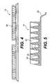
- the openings 20 are defined by a conical side wall 24 and a bottom wall surface 26 as best shown in Figs. 5 and 7.
- the conical side wall 24 may slant at any appropriate angle known in the art.
- the size and shape of the openings shown in the drawings is by way of example only. Other designs having a different arrangement of sample wells are equally suitable with the present invention.
- Sample block 14 may include a bottom flange portion 28 for resting on the base 40 of the heating apparatus or any other alternate design.
- a compression seal (not shown) may be provided between the flange portion 28 and base 40.
- the sample block of the present invention further includes the provision of portions engageable with an urging mechanism of the present invention. The engageable portions of the sample block will be described in greater detail later in the specification.
- the sample well tray 16 includes a plurality of sample wells 42 in a top surface 44 thereof, as best shown in Fig. 7.
- Sample well trays suitable for the present invention are well known in the art, and are also referred to as sample well plates.
- the present invention is flexible so that virtually any type of sample well tray may be utilized.
- the sample wells 42 shown in the Figures are of a conventional conical design known in the art.
- the sample wells may be of a variety of other shapes such as cylindrical or hemispherical.
- Each sample well 42 can hold a predefined volume of liquid sample.
- each sample well has a total volume of approximately 30 ⁇ l and a working volume of approximately 20 ⁇ l.
- the sample wells have a diameter of approximately 2.20mm and a depth of approximately 8.0mm.
- the volume and dimensions of the wells can be varied depending on the specific application, as well as depending upon the number of sample wells for the sample well tray. For example, a 384-well sample well tray will typically have a smaller sample well volume than a 96-well sample well tray.
- the sample well tray may be made out of any of the conventional materials such as polypropylene that are typically used in sample well trays that will undergo thermal cycling of biological samples.
- the present invention is also suitable with a sample tray where the wells are individual tubes that may be individually detached from the tray. Alternately, the tubes may be connected together in sets of rows or columns.
- the sample wells 42 are designed to closely mate with the conical side walls 24 of the sample block, particularly after the heated cover applies a downward force on the sample well tray.
- Fig. 7 shows the spacing between sample well tube walls 46 and the sample block side walls 24 in exaggerated form for illustration purposes only.
- sample well tray is typically made of a plastic material that is slightly deformable
- the sample wells of the sample well tray will also slightly deform to match the shape of the sample block openings 20. This ensures that the sample wells of the sample well tray will closely fit against the sample block to enhance the temperature uniformity of the sample wells of the sample well tray.
- the sample well tube walls 46 impart a force on the inside surface of the sample block side walls 24. Even after the heated cover is opened so that the platen is no longer pressed against the sample well tray, the sample wells 42 of the sample well tray have a tendency to stick inside of the sample block openings 20. A significant force may be required to loosen the sample well tray 16 from the sample block 14.
- Robots used for sample well tray removal typically only generate very weak linear forces. Robots typically are unable to impart the rocking motion which is helpful in removing the sample well trays from the sample block openings. Because the robots are typically limited to linear motions, instead of rotational motion, a much higher force is required in order to loosen the sample well tray from the sample block. The linear robot-generated forces are frequently inadequate to overcome the initial sticking force, therefore, the sample well tray may remain stuck in the sample block. Therefore, an operator may need to loosen the sample well tray from the sample block by manually prying the sample well tray from the sample block. Alternately, robots may be designed which are capable of imparting a rotational force on the sample well trays, however, these robots will typically be larger, slower, more complex, and more expensive than existing robots.
- the present invention includes an urging mechanism for urging the sample well tray away from the sample block.
- the urging mechanism tends to overcome the initial sticking force of the sample well tray in the sample block so that the sample well tray is loosened from the sample block without substantial manual or robotic assistance.
- the provision of the urging mechanism of the present invention reduces the need for an operator to help unstick the sample well tray from the sample block, saving time, and reducing costs. Additionally, the robots used for automated handling do not need to be made unnecessarily more powerful and bulky, thereby saving cost and space.
- the urging mechanism of the present invention may have a variety of designs, one of which is shown in the embodiment of Figs. 1-10.
- the present invention includes urging mechanism 18 positioned between the sample block 14 and the sample well tray 16 to urge the sample well tray away from the sample block when the heated cover is moved from the closed position to an open position.
- the urging mechanism comprises a plurality of first springs 50 and a plurality of second springs 60, as best shown in Fig. 2.
- the urging mechanism shown in Figs. 1-10 is by way of example only. The urging mechanism of the present invention is not limited to the example shown in the Figures.
- the first springs 50 are positioned in a cylindrical spring opening 52 of the sample block in one embodiment of the present invention.
- the cylindrical opening 52 is defined by the side surfaces 54 and end surface 56 of the cylindrical opening, as best shown in Fig. 7.
- the springs may be positioned on the top surface of the sample block without the provision of a cylindrical opening, depending on the amount of unsupported spring length.
- urging mechanism shown in Fig. 7 is a helical compression spring
- a variety of other types of urging mechanisms may be utilized.
- springs such as leaf springs, conical helical springs, and other springs which will import an axial force when compressed are suitable with the present invention.
- other springlike devices suitable for use include, for example, elastomeric spring members, air cylinders, fluid cylinders, dampeners, belleville washers, and electrical solenoids. Any other suitable device that may be interposed in the system for imparting an upward force on the sample well tray may be used.
- the urging mechanism merely needs to be designed so that it creates sufficient force to overcome the sticking force between the sample well tray and the sample block upon opening of the cover.
- the urging mechanism should loosen the sample well tray from the sample block so that the sample well tray can be easily removed either robotically or manually. If a spring is used, the size and spring constant of the spring must be selected so an adequate force is imparted by the spring on the sample well tray.
- first spring 50 abuts against the end surface 56 of cylindrical opening 52 in the sample block 14, as best shown in Fig. 7.
- the opposite end of spring 50 engages the lower surface 58 of the sample well tray 16.
- the Figures show the end surface 56 and lower surface 58 as being flat, other configurations may be used in order to more securely engage the spring.
- the end surface 56 of the cylindrical opening or the lower surface 58 of the sample well tray may include grooves to closely fit the interior and/or exterior of the spring.
- the urging mechanism 18 includes a plurality of first springs 50 and a plurality of second springs 60.
- the springs are positioned around an outer peripheral surface 62 of the sample block outside of the rectangular grid of sample block openings 20, as best shown in Fig. 2.
- six first springs 50 are positioned on each longitudinal side (defined as the side with the greater number of sample well openings, for example, the side with twenty-four sample block openings in Fig. 2) of the outer peripheral top surface 62 of the sample well block.
- a set of second springs 60 are positioned on each lateral side (defined as the side with the lesser number of sample well openings, for example, the side with sixteen sample block openings in Fig. 2) of the outer peripheral top surface 62 of the sample block outside of the grid of sample block openings.
- the second springs 60 are positioned on projections 70 that extend outward from the rectangular array of sample block openings on each lateral side of the top surface.
- two second springs 60 are located on each lateral side of the top surface.
- Each second spring 60 has a projection 70 for resting thereon.
- the second springs are similar to the first springs, but may be greater in size.
- the second springs 60 are typically positioned in cylindrical openings similar to those used for the first springs 50, although the cylindrical openings may not be necessary in some arrangements. With the arrangement shown in Figs. 1-10, a total of sixteen springs (twelve first springs and four second springs) are utilized on the outer periphery of the sample block 16. The number and specific arrangement of springs can be varied greatly depending on the specific application.
- the urging mechanism provide a substantially uniform force on the sample well tray in order to reduce undue bending of the sample well tray.
- the force is more evenly distributed, more lightweight and thinner sample well trays may be used. Therefore, costs can be reduced for the sample well tray production and materials if the urging mechanism distributes the upward force in a substantially uniform manner. If few, large force points were used, the tray may become locally deformed in a way that could affect the handling of the tray later in the process.
- the application of a substantially uniform spring force around the periphery of the sample well tray may help reduce evaporation losses from locations adjacent the periphery of the sample well tray by ensuring that the sample well tray is firmly and evenly placed against the heated cover. Therefore, in one embodiment, it is preferable to provide a large number of substantially uniformly spaced springs for the urging mechanism.
- Springs 50 and 60 of urging mechanism 18 provide an upward force on the sample well tray that is sufficient to overcome the sticking force caused by the cover and loosen the sample well tray from the sample block upon opening of the cover.
- the upward force applied by the springs should be less than the downward force applied by the cover or the cover will not remain closed.
- the downward force imparted by the cover is typically significantly greater than the upward force imparted by the springs in order to ensure good thermal contact between the sample wells of the sample well tray and the openings of the sample block.
- Figs. 9A-9C and 10A-10C An example of suitable type springs used in one embodiment of the urging mechanism is shown in Figs. 9A-9C and 10A-10C.
- the springs of this embodiment are helical coil springs selected to impart sufficient force to urge the sample well tray away from and slightly out of the sample block after the cover is opened.
- the first springs 50 have an outside diameter of 1.92mm, length of 6.3mm, and spring rate of 0.275kg/mm. During closing of the cover, these first springs 50 each compress 1.15mm thus imparting an ejecting force of 0.316kg each.
- the second springs 60 have an outside diameter of 3.05mm, length of 9.53mm, and spring rate of 0.987kg/mm. During closing of the cover, these second springs 60 each compress 1.55mm thus imparting an ejecting force of 1.53kg.
- the particular springs used in the above example were made of stainless steel, however other suitable materials are also acceptable.
- the springs are preferably of a low thermal mass compared to the sample block and therefore do not materially affect the performance of the system. Therefore, the sample block and sample well tray maintain a substantially uniform temperature distribution that is not affected by the urging mechanism 18.
- the heated cover 12 of the thermal cycler is positioned in a first open position.
- a sample well tray with a predetermined amount of liquid sample in some or all of the sample wells is placed on top of the sample block.
- the sample well tray 16 typically includes either an adhesive film, a heat seal film, a gap pad, or individual caps for covering each of the sample wells 42 at the time of insertion into the thermal cycler.
- the sample wells 42 are aligned with the sample block openings and inserted downward into the conical sample block openings 20.
- the heated cover is then slid so that it is placed over the sample well trays and sample block.
- the heated cover is then manually or automatically closed.
- a heated platen (or the gap pad located below the platen) of the heated cover 12 presses down on the top of the sample wells to firmly press the sample wells 42 into the sample block openings 20, as best shown in Fig. 7.
- the first and second springs 50 and 60 of the urging mechanism 18 are compressed by a bottom flat surface 58 of the sample well tray on the outside periphery of the sample wells 42.
- the compression springs impart an upward force on the sample well tray 16 while the heated cover is in its closed position. While in the closed position, the thermal cycler then thermally cycles the liquid sample in the sample well tray to undergo a PCR or other type of chemical reaction.
- the heated cover 12 is opened (either manually or automatically). As the heated cover is opened, the platen (or gap pads) of the heated cover will no longer press against the top of the sample wells. Simultaneously, the springs of the urging mechanism 18 will impart an upward force on the bottom surface 58 of the sample well tray, thereby urging the sample wells 42 out of the sample block openings 20. The springs should impart sufficient force so that the sample well tray 16 will become loosened from the sample block 14 and be raised a slight distance in an upward direction. After the sample well tray is loosened from the sample block, the sample well tray may be robotically lifted out of and away from the sample block without any additional manual steps. As previously discussed, the provision of the urging mechanism allows the sample well tray to be more quickly and efficiently removed from the sample block.
- the present invention includes a method of assisting in the removal of a sample well tray from a sample block.
- the method includes the steps of providing an initial downward force on a sample well tray by closing a cover.
- the initial downward force presses sample wells of the sample well tray into openings on a top surface of a sample block.
- the method further includes the step of providing an upward force on the sample well tray by a spring system positioned between the sample well tray and the sample block, the upward force being substantially smaller than the initial downward force.
- the cover is then opened to remove the initial downward force on the sample well tray, and the sample well tray is urged from the sample block by the upward force from the spring mechanism.
- the system and method according to the present invention reduces the amount of time that it takes to remove the sample well tray from the sample block.
- the urging mechanism arrangement allows the sample well tray to be automatically removed from the sample well block without unduly exposing an operator to the chemicals in the sample well tray which may occur during manual handling of sample well trays.
- the system and method according to the present invention are not limited by the examples shown above which are for purposes of illustration only.
- the present invention includes a heating apparatus of a second embodiment.
- the apparatus includes a heated cover, a sample block having a plurality of openings, a sample well tray having a plurality of sample wells, a sample well tray holder for supporting the sample well tray, and an urging mechanism positioned between the sample block and the sample well tray holder to urge the sample well tray away from the sample block when the heated cover is moved from a closed position to an open position.
- the heating apparatus 100 for biological samples includes a heated cover 110, a sample block 112, a sample well tray 114, a sample well tray holder 116, and an urging mechanism 118.
- the heating apparatus of the embodiment shown in Figs. 11-13 is a 96-well PE Biosystems thermal cycler with optical detection capability, however, the heating apparatus is also suitable for other types of thermal cyclers with different numbers of wells, as well as those without optical detection capabilities.
- the present invention is suitable for a heating apparatus in which sample wells are pressed into a sample block by a cover. Similar to the first embodiment, the present invention is especially suitable for use in a heating apparatus with a heated cover.
- the heating apparatus includes a heated cover.
- the heated cover 110 is located above the sample block 112, sample well tray 114, and sample well tray holder 116.
- the heated cover is operable between an open position in which the heated cover does not impart a downward force on the sample well tray, and a closed position where the heated cover imparts a downward force on the sample well tray.
- the heated cover 110 includes a central cover portion 120 and an outside cover portion 122.
- the central cover portion 120 has a plurality of openings 124 for the optical detection of reactions that occur in the sample wells of the sample well tray.
- the present invention is also suitable for use in a thermal cycler without optical detection capabilities.
- the outside cover portion 122 is movable in an upward and downward direction relative to the central cover portion 124. The movement of the outside cover portion 122 relative to the central cover portion 124 assists in isolating the spring force of an urging mechanism from the sample well tray during thermal cycling protocols.
- the heated cover 110 of Figs. 11-13 also includes a plurality of distribution springs 126 for distributing the force of the central cover portion 120 onto the sample well tray 114.
- the distribution springs 126 also allow for the upward and downward motion of the outside cover portion 122 relative to the central cover portion 120.
- Each distribution spring 126 includes a pin (not shown) positioned inside of the helical spring. The pin passes through the central cover portion 120 and is connected to the outside cover portion 122 so that the central cover portion and outside cover portion are biased toward one another.
- a driving mechanism (not shown) drives the central cover portion 124 and outside cover portion 122 in a downward direction so that the heated cover presses firmly on the sample well tray in a manner which will be described in greater detail below.
- the heating apparatus includes a sample well tray and sample well tray holder for supporting the sample well tray.
- the sample well tray 114 is a conventional sample well tray known in the art with a plurality of sample wells 115.
- the sample well tray is a 96-well tray, however the instant invention is applicable for use with sample well trays having any number of wells from one or two wells to several thousand.
- the present invention is also particularly suitable for use with 384 and 60-well trays known in the art.
- the present invention is suitable for use with sample well trays having a variety of sizes and shapes. In the example shown in Figs.
- the sample wells have a working volume of 200 ⁇ l, a diameter of 5.50mm and a depth of 20.0mm.
- the volume of the sample wells may vary anywhere from 0.1 ⁇ l to thousands of microliters ( ⁇ l), with a volume between 50 to 500 ⁇ l being typical, with a volume of 100 to 200 ⁇ l being most preferred.
- the heating apparatus of Figs. 11-13 is also suitable for use with sample trays where the liquid sample is placed on a structure other than a sample well, such as a microscope slide or a frit.
- the heating apparatus of Figs. 11-13 further includes a sample well tray holder 116 for supporting the sample well tray.
- the sample well tray holder 116 is in the shape of a flat plate with a main body portion 140 and an arm portion 142. In the example shown in the drawings, the main body portion 140 is in a rectangular shape. The main body portion 140 also defines a rectangular opening 146 for the sample well tray 114.
- the sample well tray holder is preferably made out of a material with poor heat conduction characteristics and a low thermal mass. In one embodiment, the material selected for the sample well tray holder is a polycarbonate. Other suitable materials are also acceptable.
- the arm portion 142 of the sample well tray holder 116 projects on the same plane as the main body portion 140, and is used for connection to a robotic manipulator (not shown).
- a robotic manipulator may grasp the arm portion 142 via the clamping mechanism 144 positioned on the end of the arm portion 142 and swing the main body portion into position to insert the sample well tray 114 into the heating apparatus.
- the robotic manipulator also allows for the sample well tray to be moved upward and downward over the sample block, and preferably initiates an additional downward movement on the sample tray holder to isolate the sample well tray from the urging mechanism when the cover is in its closed position, as will be described in greater detail.
- the main body portion 140 of the sample well tray holder preferably includes a plurality of bosses 150 projecting upward from the top surface thereof.
- the bosses shown in the Figures are for purposes of illustration only, as the bosses can be of any variety of sizes, shapes, and designs.
- the bosses could also be a ridge around the outside periphery of the opening for the sample well tray.
- the bosses could also be significantly lengthened compared to those shown in Fig. 12. The function of the bosses will be described in greater detail below.
- the rectangular opening 146 of the sample well tray holder is designed so that the sample well tray 114 may rest on the sample well tray holder 116. This is shown for example in the schematic of Figs. 13A-13C.
- the rectangular opening 146 is defined by a tapered wall 160 which tapers downward from the top surface 162 of the sample well tray holder 116.
- the opening defined by the tapered wall 160 is greater in length and width than the length and width of the sample well tray 114.
- the tapered wall 160 tapers until it meets a floor portion 164 which extends from the tapered wall 160.
- the floor portion 164 extends along the bottom surface 166 of the sample well tray holder.
- the floor portion 164 defines a rectangular opening that is smaller than the size of the sample well tray.
- the heating apparatus includes a sample block including a plurality of openings for the sample wells of the sample well tray.
- the sample block 112 includes a plurality of sample block openings 130 in a top surface 132 of the sample block.
- the openings are defined by conical side walls 134 similar to those described for Figs. 1-10 and a bottom surface 136.
- the sample block 112 is positioned in a base 200 for supporting the sample block.
- base 200 includes a raised surface 202, a first lower surface 204, a second lowered surface 206, and third lowered surface 208.
- the first lowered surface 204 is sized to accommodate the main body portion 140 of the sample well tray holder 116. Additionally, the first lowered surface 204 defines a recess for receiving the sample block 112 therein.
- the second and third lowered surfaces, 206 and 208, are sized to also accommodate the sample well tray holder.
- the first lowered surface 204 of the base is configured to engage the urging mechanism as will be described below.
- the heating apparatus includes an urging mechanism for urging the sample well tray out of the sample well block upon opening of the cover.
- the urging mechanism 118 may include any suitable type of mechanism such as a spring device for pressing upward on the sample well tray holder and sample well tray when the heated cover is opened.
- the urging mechanism 118 includes a plurality of springs. More particularly, the plurality of springs comprise leaf springs 180 attached to a bottom surface 166 of the sample well tray holder 116. The leaf springs, in one embodiment, are attached to the bottom surface 166 of the sample well tray holder. Alternately, the leaf springs could be attached to the sample well block.
- the leaf springs 180 were attached to the sample well tray holder, instead of the sample block, in order to make cleaning of the heating apparatus more easy. Additionally, the arrangement of the leaf springs on the sample well tray reduces the thermal effect of the leaf springs on the sample block, compared to if the leaf springs were attached to the sample block.
- leaf springs 180 are attached to the bottom surface 166 of the sample well tray holder 116.
- the four leaf springs are substantially symmetrically spaced around the sample well tray.
- the Figures show four leaf springs, anywhere from one to several dozen leaf springs could be used with the present invention. It is desirable that the leaf spring be comprised of a non-corrosive material that will maintain reasonably constant spring characteristics. In one embodiment, the material for the leaf spring is beryllium copper. Any other suitable material is also acceptable.
- the urging mechanism of the present invention is not limited to the design shown in Figs. 11-13.
- the urging mechanism may also be made out of any variety of force imparting devices instead of the leaf springs shown in Figs. 11-13 such as coil springs, hydraulic dampeners, elastomeric springs, or other conventional spring devices.
- Leaf springs were selected in the particular embodiment because of the large distance between the bottom surface 166 of the sample well tray 114 and the first lower surface 204 of the base 200.
- the use of a coil spring is possible with this configuration, however there may be a substantial amount of unsupported spring length if a coil spring is used. Therefore, types of springs besides coil springs may be desirable if the amount of unsupported spring length is substantial in the particular configuration.
- Fig. 12 shows a row of sample well caps 210 for covering the top of the sample wells 115.
- the caps may be individual, or grouped in rows of eight as shown in Fig. 12.
- an adhesive film can be used to seal off the sample wells.
- Another typical type of seal known in the art is a heat seal film. Any of these known structures may be utilized for covering the sample wells.
- a thin compliant cover may be placed between the heated cover and the top of the sample well tray.
- This compliant cover is similar to the gap pad that may be utilized in the Figs. 1-10 embodiment, but does not typically supply a seal to the top of the sample wells.
- the compliant cover serves the function of the cover and gap pad.
- An example of a typical compliant cover is shown in Figs. 13A-13C, as reference number 212.
- the compliant cover 212 helps to evenly distribute the downward force imparted by the heated cover onto the sample well tray.
- the compliant cover may be made out of a polymeric, composite material or other material that can withstand the high temperatures experienced during thermal cycling. The compliant cover of Figs.
- the compliant cover typically includes detection holes 214 aligned with each of the sample wells 115 of the sample well tray 114.
- the detection holes 214 are also aligned with the openings 124 on the central cover portion 120 of the heated cover for allowing light emissions from the liquid sample to be detected by a detection apparatus (not shown).
- the heated cover 12 of the thermal cycler is positioned in a first open position.
- the sample well tray 114 is then placed into the sample well tray holder 116 either manually or automatically.
- the sample wells 115 of the sample well tray have already been filled with the appropriate biological liquid samples.
- the sample wells have also been sealed by the appropriate method, such as placement of caps 210 on the sample wells.
- the sample well tray holder 116 is then rotated by the robotic manipulator so that the sample well tray holder and sample well tray are positioned between the heated cover 110 and the sample block 112 as shown in Fig. 13A.
- the sample well tray holder 116 and sample well tray 114 are lowered so that the sample wells 115 are positioned inside the sample block openings 130.
- the sample well tray holder and sample well tray are lowered by either the robotic manipulator moving them downward or by pressing the heated cover 110 downward, depending on the particular configuration.
- the heated cover 110 is moved downward by either manual or automatic operation, so that the sample wells 115 of the sample well tray 114 are pressed firmly into the openings 130 of the sample block as shown in Fig. 13B.
- Fig. 13B illustrates the heated cover in a closed position, which will be referred to as the "seated" position.
- the leaf springs 180 are compressed between the sample well tray holder 116 and the first lowered surface 204 of the base.
- the bottom surface 166 of the sample well tray holder 116 is spaced by the distance of y 1 from the top surface 204 of the base.
- the top surface 170 of the floor portion 164 of the sample well tray holder is pressed against the bottom of the side wall 168 of the sample well tray by the spring force of leaf springs 180.
- the upward force imparted on the side wall of the sample well tray has a tendency to cause bending of the sample well tray.
- a heated cover actuator (not shown) will press downward on the outside cover portion 122 of the heated cover 110 so that the sample well tray holder 116 will move slightly downward relative to the sample well tray 114 to the position shown in Fig. 13C.
- the top surface 170 of the floor portion 164 will become spaced from the bottom of the side wall 168 in order to isolate the sample well tray 114 from the spring force generated by the leaf spring 180 while in the compressed position shown in Fig. 13C.
- 13C will be referred to as the compressed position, because the leaf spring is compressed even farther so that the spacing between the bottom surface 166 of the sample well tray holder 116 and the top surface 204 of the base is reduced to a measurement of y 2 .
- the sample well tray holder 116 In the compressed position, the sample well tray holder 116 will not press upward on the side wall 168 thereby substantially preventing bending of the sample well tray 114. This reduces the amount of volume loss due to bending.
- the heating apparatus is thermally cycled upon being positioned in the compressed position of Fig. 13C. After the apparatus has been thermally cycled, the mechanism for driving the heated cover downward is released in order to open the cover. The heated cover no longer contacts the top of the sample well tray.
- the leaf spring 180 simultaneously pushes the sample well tray holder 116 upward.
- the top surface 170 of the floor portion 164 then engages the bottom of the side wall 168 of the sample well tray 114, and pushes upward on the sample well tray.
- the force imparted on the sample well tray is sufficient to overcome the initial sticking force, and the sample well tray is loosened from the sample block.
- the sample well tray 114 is thus safely ejected from the sample block 112 so that the robotic manipulator may remove the sample well tray holder and sample well tray from the sample block.
Landscapes
- Chemical & Material Sciences (AREA)
- Health & Medical Sciences (AREA)
- Clinical Laboratory Science (AREA)
- General Health & Medical Sciences (AREA)
- Chemical Kinetics & Catalysis (AREA)
- Biochemistry (AREA)
- Hematology (AREA)
- Life Sciences & Earth Sciences (AREA)
- Analytical Chemistry (AREA)
- Molecular Biology (AREA)
- Automatic Analysis And Handling Materials Therefor (AREA)
- Apparatus Associated With Microorganisms And Enzymes (AREA)
- Devices For Use In Laboratory Experiments (AREA)
- Sampling And Sample Adjustment (AREA)
- Agricultural Chemicals And Associated Chemicals (AREA)
- Solid-Sorbent Or Filter-Aiding Compositions (AREA)
- Immobilizing And Processing Of Enzymes And Microorganisms (AREA)
- Investigating Or Analysing Biological Materials (AREA)
Claims (37)
- Système pour retirer une plaque de puits à échantillons (16, 114) ayant au moins un puits à échantillons d'un bloc d'échantillons (14, 112), ayant une ouverture pour recevoir au moins un puits respectif à échantillons de la plaque de puit à échantillons (16, 114) dans celle-ci, et au moins un mécanisme de déplacement (18, 118) caractérisé en ce que ledit mécanisme de déplacement (18, 118) est interposé entre le bloc d'échantillons (14, 112) et la plaque de puits à échantillons (16, 114) et comprend au moins un dispositif de ressort positionné dans une région à l'extérieur de ladite ouverture du bloc d'échantillons (14, 112) pour transmettre une force de déplacement sur la plaque de puits à échantillons, dans lequel ladite force de déplacement déplace la plaque de puit à échantillons (16, 114) pour la retirer du bloc d'échantillons (14, 112) lors de l'élimination d'une force d'appui transmise sur la partie supérieure du puits à échantillons.
- Système selon la revendication 1, dans lequel ladite force d'appui est suffisante pour contrer ladite force de déplacement pour retenir la plaque de puits à échantillons (16, 114) contre le bloc d'échantillons (14, 112) lorsque ladite force d'appui est transmise.
- Système selon les revendications 1 à 2, dans lequel ledit mécanisme de déplacement (18, 118) peut venir en prise avec la plaque d'échantillons.
- Système selon les revendications 1 à 3, dans lequel le bloc d'échantillons (14, 112) comprend une pluralité d'ouvertures pour recevoir des puits à échantillons (115) de la plaque d'échantillons, lesdits puits à échantillons (115) étant retirés du bloc d'échantillons (14, 112) au cours du fonctionnement du mécanisme de déplacement (18, 118).
- Système selon l'une quelconque des revendications précédentes, dans lequel ledit mécanisme de déplacement (18, 118) comprend une pluralité de dispositif de ressorts.
- Système selon l'une quelconque des revendications précédentes, dans lequel le bloc d'échantillons (14, 112) comprend en outre au moins une partie de réception pour recevoir une partie au moins dudit dispositif de ressort.
- Système selon l'une quelconque des revendications précédentes, dans lequel au moins un dispositif de ressort comprend un ressort hélicoïdal (50, 60).
- Système selon l'une quelconque des revendications précédentes, dans lequel la partie de réception comprend une ouverture cylindrique pour loger une partie du ressort hélicoïdal (50, 60).
- Système selon l'une quelconque des revendications précédentes, dans lequel les dispositifs de ressort sont positionnés de façon sensiblement symétrique autour de la périphérie du bloc d'échantillons (14, 112).
- Système selon l'une quelconque des revendications précédentes, dans lequel le mécanisme de déplacement (18, 118) comprend une pluralité de dispositifs de ressort espacés autour d'une périphérie extérieure (62) d'une surface supérieure du bloc d'échantillons (14, 112), lesdits dispositifs de ressort étant logés dans des ouvertures cylindriques dans le bloc d'échantillons (14, 112), lesdits dispositifs de ressort venant en prise avec une surface inférieure de la plaque de puits à échantillons (16, 114) afin de fournir la force de déplacement pour désengager la plaque de puits à échantillons (16, 114) du bloc d'échantillons (14, 112) lors de l'ouverture d'un couvercle (12, 110) pour le système, ledit couvercle étant configuré pour fournir la force d'appui sur le dessus la plaque de puits à échantillons.
- Système selon l'une quelconque des revendications précédentes, comprenant en outre un dispositif de support de plaque de puits à échantillons (116) pour maintenir la plaque de puits à échantillons (16, 114), ledit puits à échantillons étant mobile par rapport au dispositif de support de plaque de puits à échantillons (116).
- Système selon la revendication 11, dans lequel ledit mécanisme de déplacement (18, 118) pousse le dispositif de support de plaque de puits à échantillons (116) pour l'éloigner du bloc d'échantillons (14, 112) pour ainsi déplacer les puits à échantillons (115) hors des ouvertures dans le bloc d'échantillons (14, 112) lors de l'élimination de la force d'appui qui se produit lors de l'ouverture d'un couvercle (12, 110) pour la plaque de puits à échantillons (16, 114).
- Système selon les revendications 11 à 12, dans lequel une partie du dispositif de ressorts est attachée au dispositif de support de plaque de puits à échantillons (116).
- Système selon les revendications 11 à 13, dans lequel les dispositifs de ressorts sont positionnés sensiblement uniformément autour d'une ouverture pour la plaque de puits à échantillons (16, 114) sur la partie inférieure du dispositif de support de plaque de puits à échantillons (116).
- Système selon l'une quelconque des revendications précédentes, comprenant quatre desdits dispositif de ressorts.
- Système selon la revendication 15, dans lequel ledit dispositif de ressorts comprend des ressorts à lames.
- Système selon la revendication 1, dans lequel les puits à échantillons reçus par le bloc d'échantillons sont dimensionnés pour avoir un volume de fluide dans un intervalle de 10 à 500 µL.
- Système selon l'une quelconque des revendications précédentes, dans lequel le déplacement d'une plaque d'échantillons pour l'éloigner d'un bloc d'échantillons (14, 112) dans un dispositif de chauffage d'échantillons biologiques, comprend un ressort positionné entre le bloc d'échantillons (14, 122) et la plaque d'échantillons, ledit ressort ayant une force suffisante dans un état comprimé pour déplacer la plaque d'échantillons dans une direction l'éloignant sensiblement du bloc d'échantillons (14, 112) en réponse à l'ouverture d'un couvercle (12, 110) pour l'éloigner de la plaque de puits à échantillons (16, 114).
- Procédé de manipulation d'une plaque de puits à échantillons par rapport à un bloc d'échantillons, caractérisé en ce que le procédé comprend les étapes consistant à fournir une force descendante initiale sur une plaque de puits à échantillons (16, 114), ladite force descendante initiale poussant le puits à échantillons (115) de la plaque de puits à échantillons (16, 114) dans une ouverture d'une surface supérieure d'un bloc d'échantillons (14, 112) ; et fournir une force ascendante sur la plaque de puits à échantillons (16, 114), la force ascendante étant fournie par un dispositif de ressort d'un mécanisme de déplacement (18, 118) interposé entre le bloc d'échantillons (14, 112) et la plaque de puits à échantillons (16, 114), dans lequel le dispositif de ressort est positionné dans une région à l'extérieur de ladite ouverture du bloc d'échantillons (14, 112).
- Procédé selon la revendication 19, dans lequel le système de ressort comprend au moins un dispositif de ressort en communication avec le bloc d'échantillons (14, 112).
- Procédé selon la revendication 19 à 20, dans lequel le bloc d'échantillons (14, 112) comprend une pluralité d'ouvertures pour recevoir des puits à échantillons (115) de la plaque d'échantillons, lesdits puits à échantillons (115) étant déplacés pour être éloignés du bloc d'échantillons (14, 112) au cours du fonctionnement du mécanisme de déplacement (18, 118).
- Procédé selon les revendications 19 à 20, dans lequel le mécanisme de déplacement (18, 118) vient en prise avec la plaque de puits à échantillons (16, 114) qui est proposée avec une surface supérieure plate pour recevoir les échantillons d'un matériel biologique.
- Procédé selon les revendications 19 à 22, comprenant les étapes consistant à réduire la force descendante initiale sur la plaque de puits à échantillons (16, 114), et éloigner ladite plaque de puits à échantillons (16, 114) du bloc d'échantillons (14, 112) par une force ascendante entre la plaque de puits à échantillons (16, 114) et le bloc d'échantillons (14, 112).
- Procédé selon les revendications 19 à 23, comprenant en outre l'étape consistant à retirer la plaque de puits à échantillons (16, 114) du bloc d'échantillons (14, 112) par l'intermédiaire d'un mécanisme robotisé.
- Procédé selon la revendication 19 à 24, dans lequel au cours de l'étape consistant à fournir une force ascendante sur la plaque de puits à échantillons (16, 114), une pluralité de dispositif de ressorts viennent en prise avec la plaque de puits à échantillons (16, 114).
- Procédé selon les revendications 19 à 25, dans lequel au cours de l'étape consistant à fournir une force ascendante sur la plaque de puits à échantillons (16, 114), un dispositif de support de plaque de puits à échantillons (116) est utilisé pour pousser la plaque de puits à échantillons (16, 114) dans une direction ascendante.
- Procédé selon les revendications 19 à 26, dans lequel avant l'étape consistant à fournir une force ascendante sur la plaque de puits à échantillons (16, 114), la force ascendante transmise sur le dispositif de support de plaque de puits à échantillons (116) par le système de ressort est sensiblement isolée à partir de la plaque de puits à échantillons (16, 114), de telle sorte que sensiblement aucune force ascendante n'est transmise sur le dispositif de support de plaque de puits à échantillons (116) par la plaque de puits à échantillons (16, 114) au cours d'une procédure de chauffage réalisée par l'appareil.
- Appareil de chauffage pour échantillon biologique, comprenant un système selon la revendication 1.
- Appareil de chauffage selon la revendication 28, comprenant en outre un couvercle, dans lequel : la plaque de puits à échantillons (16, 114) comprend une pluralité de puits à échantillons, et le bloc d'échantillons (14, 112) comprend une pluralité d'ouvertures dans une partie supérieure de celui-ci pour recevoir la pluralité de puits à échantillons (115) de la plaque de puits à échantillons (16, 114) ; et le mécanisme de déplacement (18, 118) pouvant venir en prise entre le bloc d'échantillons (14, 112) et la plaque de puits à échantillons (16, 114) pour déplacer la plaque de puits à échantillons (16, 114) et l'éloigner du bloc d'échantillons (14, 112) lorsque le couvercle (12, 110) est déplacé à partir d'une position fermée vers une position ouverte, dans lequel ledit couvercle (12, 110) transmet une force descendante sur la partie supérieure de la plaque de puits à échantillons (16, 114) pour pousser les puits à échantillons (115) dans les ouvertures du bloc d'échantillons (14, 112) lorsque le couvercle (12, 110) est déplacé vers une position fermée, ledit mécanisme de déplacement (18, 118) transmettant une force ascendante à la plaque de puits à échantillons (16, 114), et dans lequel ladite force descendante transmise par le couvercle (12, 110) est suffisante pour retenir la plaque de puits à échantillons (16, 114) contre le bloc d'échantillons (14, 112) lorsque le couvercle (12, 110) est dans ladite position fermée.
- Appareil de chauffage selon la revendication 29, dans lequel une plaque de puits à échantillons (16, 114) peut être positionnée entre le couvercle (12, 110) et le bloc d'échantillons (14, 112) lorsque le couvercle (12, 110) est dans une position fermée.
- Appareil de chauffage selon les revendications 28 à 30, dans lequel au moins un dispositif de ressort vient en prise avec le bloc d'échantillons (14, 112) de telle sorte que au moins un dispositif de ressort soit positionné sur une surface du bloc d'échantillons (14, 112) de façon radiale à l'extérieur des ouvertures dans le bloc d'échantillons (14, 112).
- Appareil de chauffage selon les revendications 28 à 31, dans lequel le mécanisme de déplacement (18, 118) comprend une pluralité de ressorts.
- Appareil de chauffage selon les revendications 28 à 32, dans lequel le bloc d'échantillons (14, 112) comprend en outre une pluralité d'ouvertures de ressort cylindriques pour recevoir une pluralité de dispositif de ressorts du mécanisme de déplacement (18, 118).
- Appareil de chauffage selon les revendications 28 à 33, comprenant en outre un dispositif de support de plaque de puits à échantillons (116), le dispositif de support de plaque de puits à échantillons (116) supportant la plaque de puits à échantillons (16, 114), la plaque de puits à échantillons (16, 114) étant mobile par rapport au dispositif de support de plaque de puits à échantillons (116).
- Appareil de chauffage selon la revendication 34, dans lequel le mécanisme de déplacement (18, 118) est positionné sur une surface inférieure du dispositif de support de plaque de puits à échantillons (116).
- Appareil de chauffage selon les revendications 34 à 35, dans lequel le dispositif de support de plaque de puits à échantillons (116) peut être poussé vers la bas par une partie extérieure du couvercle chauffé (12, 110) de telle sorte que la plaque de puits à échantillons (16, 114) soit désengagée du dispositif de support de plaque de puits à échantillons (116), le mécanisme de déplacement (18, 118) ne transmettant plus de force ascendante sur la plaque de puits à échantillons (16, 114) dans cette position.
- Appareil de chauffage selon les revendications 34 à 36, dans lequel la plaque de puits à échantillons (16, 114) reçoit ladite force ascendante du dispositif de support de plaque de puits à échantillons (116) lorsque la partie extérieure du couvercle chauffé (12, 110) n'est plus poussée vers le bas de telle sorte que le dispositif de support de plaque de puits à échantillons (116) vient en prise avec la plaque de puits à échantillons (16, 114).
Applications Claiming Priority (3)
| Application Number | Priority Date | Filing Date | Title |
|---|---|---|---|
| US496408 | 2000-02-02 | ||
| US09/496,408 US7169355B1 (en) | 2000-02-02 | 2000-02-02 | Apparatus and method for ejecting sample well trays |
| PCT/US2001/003265 WO2001056697A1 (fr) | 2000-02-02 | 2001-02-01 | Appareil et procede d'ejection de plaques a puits |
Publications (2)
| Publication Number | Publication Date |
|---|---|
| EP1165237A1 EP1165237A1 (fr) | 2002-01-02 |
| EP1165237B1 true EP1165237B1 (fr) | 2004-06-09 |
Family
ID=23972495
Family Applications (1)
| Application Number | Title | Priority Date | Filing Date |
|---|---|---|---|
| EP01908775A Expired - Lifetime EP1165237B1 (fr) | 2000-02-02 | 2001-02-01 | Appareil et procede d'ejection de plaques a puits |
Country Status (8)
| Country | Link |
|---|---|
| US (3) | US7169355B1 (fr) |
| EP (1) | EP1165237B1 (fr) |
| JP (1) | JP2003521716A (fr) |
| AT (1) | ATE268643T1 (fr) |
| AU (1) | AU765790B2 (fr) |
| CA (1) | CA2366978C (fr) |
| DE (1) | DE60103698T2 (fr) |
| WO (1) | WO2001056697A1 (fr) |
Families Citing this family (67)
| Publication number | Priority date | Publication date | Assignee | Title |
|---|---|---|---|---|
| US6893877B2 (en) | 1998-01-12 | 2005-05-17 | Massachusetts Institute Of Technology | Methods for screening substances in a microwell array |
| US6906292B2 (en) * | 1998-10-29 | 2005-06-14 | Applera Corporation | Sample tray heater module |
| NZ513390A (en) | 1999-03-19 | 2003-01-31 | Genencor Int | Multi-through hole testing plate for high throughput screening |
| EP1088590B1 (fr) | 1999-09-29 | 2003-04-16 | Tecan Trading AG | Thermocycleur et élément de levage pour plaque de microtitrage |
| US7169355B1 (en) * | 2000-02-02 | 2007-01-30 | Applera Corporation | Apparatus and method for ejecting sample well trays |
| US20020151040A1 (en) | 2000-02-18 | 2002-10-17 | Matthew O' Keefe | Apparatus and methods for parallel processing of microvolume liquid reactions |
| US6719949B1 (en) * | 2000-06-29 | 2004-04-13 | Applera Corporation | Apparatus and method for transporting sample well trays |
| DE10115848A1 (de) * | 2001-03-30 | 2002-10-10 | Biometra Biomedizinische Analy | Vorrichtung zur thermischen Beeinflussung von in einem Behältnis enthaltenem, vorzugsweise flüssigem Probenmaterial |
| US6514750B2 (en) * | 2001-07-03 | 2003-02-04 | Pe Corporation (Ny) | PCR sample handling device |
| US7459302B2 (en) * | 2001-10-02 | 2008-12-02 | Stratagene California | Side-wall heater for thermocycler device |
| DE20117661U1 (de) * | 2001-10-29 | 2003-03-13 | MWG-BIOTECH AG, 85560 Ebersberg | Thermocyclervorrichtung |
| US7349597B2 (en) | 2001-12-21 | 2008-03-25 | Opnext, Inc. | Grating based multiplexer/demultiplexer component |
| DE10211324B4 (de) * | 2002-03-14 | 2010-02-11 | Mohr, Ulrich, Prof. Dr. med. | Kultur/Expositionsvorrichtungen |
| US7452712B2 (en) * | 2002-07-30 | 2008-11-18 | Applied Biosystems Inc. | Sample block apparatus and method of maintaining a microcard on a sample block |
| GB0219393D0 (en) * | 2002-08-20 | 2002-09-25 | Quanta Biotech Ltd | Control apparatus |
| US8277753B2 (en) | 2002-08-23 | 2012-10-02 | Life Technologies Corporation | Microfluidic transfer pin |
| US6730883B2 (en) * | 2002-10-02 | 2004-05-04 | Stratagene | Flexible heating cover assembly for thermal cycling of samples of biological material |
| WO2004074818A2 (fr) | 2002-12-20 | 2004-09-02 | Biotrove, Inc. | Appareil et procede de dosage utilisant des reseaux microfluidiques |
| US20060094108A1 (en) * | 2002-12-20 | 2006-05-04 | Karl Yoder | Thermal cycler for microfluidic array assays |
| DE20301279U1 (de) * | 2003-01-28 | 2003-04-10 | HTI bio-X GmbH, 85560 Ebersberg | Reaktionsgefäß |
| CA2559171A1 (fr) | 2004-03-12 | 2005-09-29 | Biotrove, Inc. | Chargement d'ensembles d'echantillons de l'ordre du nanolitre |
| US20080118955A1 (en) * | 2004-04-28 | 2008-05-22 | International Business Machines Corporation | Method for precise temperature cycling in chemical / biochemical processes |
| US20050244933A1 (en) * | 2004-04-28 | 2005-11-03 | International Business Machines Corporation | Method and apparatus for precise temperature cycling in chemical/biochemical processes |
| DE102004024350A1 (de) * | 2004-05-17 | 2005-12-15 | H+P Labortechnik Ag | Reaktionsgefäß sowie dessen Herstellung und Verwendung |
| US20050282270A1 (en) * | 2004-06-21 | 2005-12-22 | Applera Corporation | System for thermally cycling biological samples with heated lid and pneumatic actuator |
| DE102005027555B3 (de) * | 2005-06-14 | 2006-10-05 | Eppendorf Ag | Thermocycler |
| US20070175897A1 (en) | 2006-01-24 | 2007-08-02 | Labcyte Inc. | Multimember closures whose members change relative position |
| WO2007146443A2 (fr) * | 2006-06-14 | 2007-12-21 | Oldenburg Kevin R Ph D | dispositifs de cyclage thermique et procédés d'utilisation de ceux-ci |
| PL1873521T3 (pl) * | 2006-06-27 | 2012-02-29 | Hoffmann La Roche | Diagnostyczna kaseta z taśmą |
| US20080128431A1 (en) * | 2006-12-01 | 2008-06-05 | Gradzewicz Lisa M | Warming container for wipes |
| US7631761B2 (en) * | 2006-12-01 | 2009-12-15 | Lmg Enterprises, Llc | Warming container for wipes |
| US20090181359A1 (en) * | 2007-10-25 | 2009-07-16 | Lou Sheng C | Method of performing ultra-sensitive immunoassays |
| US8222048B2 (en) | 2007-11-05 | 2012-07-17 | Abbott Laboratories | Automated analyzer for clinical laboratory |
| CN202830041U (zh) * | 2009-04-03 | 2013-03-27 | Illumina公司 | 用于加热生物样本的设备 |
| GB2471856A (en) * | 2009-07-14 | 2011-01-19 | Mantis Deposition Ltd | Sample holder |
| GB2512764B (en) * | 2009-08-08 | 2014-12-24 | Bibby Scient Ltd | An apparatus for treating a test sample |
| GB2511693A (en) * | 2009-08-08 | 2014-09-10 | Bibby Scient Ltd | An apparatus for treating a test sample |
| CN201837588U (zh) * | 2009-09-09 | 2011-05-18 | 海利克斯公司 | 用于多个反应的光学系统 |
| JP5280984B2 (ja) * | 2009-10-23 | 2013-09-04 | 株式会社日立ハイテクノロジーズ | 保温装置及びそれを備えた分析装置 |
| DE102010019232B4 (de) * | 2010-05-03 | 2013-06-27 | Eppendorf Ag | Kondensatvermeidungshaube |
| EP2646542B1 (fr) * | 2010-12-03 | 2023-10-18 | BioFire Defense, LLC | Appareil thermocycleur |
| SG191073A1 (en) * | 2010-12-08 | 2013-07-31 | Life Technologies Corp | Control systems and methods for biological applications |
| TW201239088A (en) * | 2011-03-22 | 2012-10-01 | Genereach Biotechnology Corp | Convective polymerase chain reaction device |
| DE102011051097B4 (de) * | 2011-06-16 | 2013-08-08 | Leica Biosystems Nussloch Gmbh | Mikrotom zum Schneiden von histologischen Proben mit wendelförmigem Kapillarrohr |
| WO2013181138A1 (fr) * | 2012-05-29 | 2013-12-05 | Arryx, Inc. | Procédé d'incubation à deux étapes à vitesse élevée et appareil de test diagnostique in vitro |
| US20140112829A1 (en) * | 2012-10-22 | 2014-04-24 | Qiagen Gaithersburg, Inc. | Tube strip handling and heating apparatus |
| US10239059B2 (en) | 2013-03-19 | 2019-03-26 | Life Technologies Corporation | Thermal cycler cover |
| GB201319759D0 (en) * | 2013-11-08 | 2013-12-25 | Thomsen Lars | Device and method for heating a fluid chamber |
| DE102013114732A1 (de) * | 2013-12-20 | 2015-06-25 | Hamilton Bonaduz Ag | Abdeckvorrichtung, insbesondere Deckel für die Abdeckung von Reaktionsgefäßen |
| WO2015126621A1 (fr) * | 2014-02-18 | 2015-08-27 | Life Technologies Corporation | Appareils, systèmes et procédés pour fournir des dispositifs à cycle thermique pouvant être mis à l'échelle et isoler des dispositifs thermoélectriques |
| CA3187726A1 (fr) | 2014-08-08 | 2016-02-11 | Fremon Scientific, Inc. | Sac intelligent servant a la detection de parametres physiologiques et/ou physiques de sacs contenant une substance biologique |
| GB201501429D0 (en) * | 2015-01-28 | 2015-03-11 | British American Tobacco Co | Apparatus for heating aerosol generating material |
| US11583862B2 (en) | 2015-09-15 | 2023-02-21 | Life Technologies Corporation | Systems and methods for biological analysis |
| WO2017048987A1 (fr) * | 2015-09-15 | 2017-03-23 | Life Technologies Corporation | Systèmes et procédés d'analyse biologique |
| AU2016331926B2 (en) | 2015-10-01 | 2021-12-09 | Berkeley Lights, Inc. | Well-plate incubator |
| SG11201805240PA (en) | 2015-12-22 | 2018-07-30 | Life Technologies Corp | Thermal cycler systems and adaptor |
| WO2017169192A1 (fr) * | 2016-03-28 | 2017-10-05 | 富士フイルム株式会社 | Récipient pour pcr |
| CN106479860B (zh) * | 2016-10-14 | 2019-10-15 | 上海爱易生物医学科技股份有限公司 | 一种自动封口的荧光定量pcr仪 |
| CN110366591A (zh) * | 2016-12-01 | 2019-10-22 | 伯克利之光生命科技公司 | 井孔板培养器 |
| GB201700812D0 (en) | 2017-01-17 | 2017-03-01 | British American Tobacco Investments Ltd | Apparatus for heating smokable material |
| US20180324900A1 (en) | 2017-05-04 | 2018-11-08 | Fremon Scientific, Inc. | Dry Heat Thawing of Biological Substances |
| US20190137481A1 (en) | 2017-11-03 | 2019-05-09 | The Regents Of The University Of California | Device and method for cell-based drug screening |
| WO2019217488A1 (fr) | 2018-05-07 | 2019-11-14 | Fremon Scientific, Inc. | Décongélation de substances biologiques |
| EP3814013A4 (fr) * | 2018-06-28 | 2022-03-30 | Seegene, Inc. | Bloc thermique |
| DE102018131123A1 (de) * | 2018-12-06 | 2020-06-10 | Analytik Jena Ag | Deckel für eine Mikrotiterplatte |
| GB2583753B (en) * | 2019-05-09 | 2022-09-07 | Pyramid Innovation Ltd | A laboratory sample cassette |
| US20240382970A1 (en) * | 2023-05-19 | 2024-11-21 | Opentrons LabWorks Inc. | Apparatus for controlled release of a thermocycler seal |
Family Cites Families (59)
| Publication number | Priority date | Publication date | Assignee | Title |
|---|---|---|---|---|
| US3080759A (en) | 1958-12-19 | 1963-03-12 | Exxon Research Engineering Co | Sampling device |
| US3634651A (en) | 1970-12-04 | 1972-01-11 | Becton Dickinson Co | Serological incubator |
| US3847200A (en) | 1972-05-01 | 1974-11-12 | Brinkmann Instr Inc | Apparatus for concentrating laboratory specimens by evaporation |
| US3933165A (en) | 1974-08-20 | 1976-01-20 | Gulf Research & Development Company | Apparatus for octane monitoring |
| DE2544533A1 (de) | 1975-10-04 | 1977-04-07 | Bayer Ag | Lagervorrichtung zur vorratshaltung von probenbehaeltern |
| US4094641A (en) | 1977-02-25 | 1978-06-13 | Waters Associates, Inc. | Low loss sample bottle assembly |
| SE8306052D0 (sv) | 1983-11-03 | 1983-11-03 | Pharmacia Ab | Anordning for hantering av porosa analysmatriser |
| JPH0619321B2 (ja) | 1986-06-27 | 1994-03-16 | 東ソー株式会社 | マイクロプレ−ト用吸光度測定装置 |
| US4948564A (en) | 1986-10-28 | 1990-08-14 | Costar Corporation | Multi-well filter strip and composite assemblies |
| JPS6480864A (en) | 1987-09-24 | 1989-03-27 | Fuji Photo Film Co Ltd | Biochemical analyzer |
| US5159197A (en) | 1988-02-16 | 1992-10-27 | Difco Laboratories | Luminescence test and exposure apparatus |
| US5188963A (en) | 1989-11-17 | 1993-02-23 | Gene Tec Corporation | Device for processing biological specimens for analysis of nucleic acids |
| FR2642156B1 (fr) | 1989-01-20 | 1994-05-20 | Bertin Et Cie | Procede et dispositif de regulation rapide d'une temperature de paroi |
| JP2727015B2 (ja) | 1989-05-17 | 1998-03-11 | スズキ株式会社 | マイクロプレート用アタッチメント |
| US5346672A (en) | 1989-11-17 | 1994-09-13 | Gene Tec Corporation | Devices for containing biological specimens for thermal processing |
| DK0528882T3 (da) | 1990-05-03 | 2008-01-14 | Cornell Res Foundation Inc | DNA-amplifikationssystem til påvisning af genetiske sygdomme ved hjælp af termostabil ligase |
| DE4022794A1 (de) | 1990-07-18 | 1992-02-06 | Max Planck Gesellschaft | Verfahren zur herstellung einer platte mit zumindest einer nach oben offenen mulde zur aufnahme von chemischen und/oder biochemischen und/oder mikrobiologischen substanzen und nach dem verfahren hergestellte platte |
| US5582665A (en) | 1990-07-18 | 1996-12-10 | Max-Planck-Gesellschaft Zur Forderung Der Wissenschaften E.V. | Process for sealing at least one well out of a number of wells provided in a plate for receiving chemical and/or biochemical and/or microbiological substances, and installation for carrying out the process |
| US5210015A (en) | 1990-08-06 | 1993-05-11 | Hoffman-La Roche Inc. | Homogeneous assay system using the nuclease activity of a nucleic acid polymerase |
| US5282543A (en) | 1990-11-29 | 1994-02-01 | The Perkin Elmer Corporation | Cover for array of reaction tubes |
| KR100236506B1 (ko) | 1990-11-29 | 2000-01-15 | 퍼킨-엘머시터스인스트루먼츠 | 폴리머라제 연쇄 반응 수행 장치 |
| US5264184A (en) * | 1991-03-19 | 1993-11-23 | Minnesota Mining And Manufacturing Company | Device and a method for separating liquid samples |
| EP0542422A1 (fr) | 1991-11-12 | 1993-05-19 | General Atomics | Plaque de microtitrage à puits multiples |
| US5459300A (en) | 1993-03-03 | 1995-10-17 | Kasman; David H. | Microplate heater for providing uniform heating regardless of the geometry of the microplates |
| US6258325B1 (en) | 1993-04-19 | 2001-07-10 | Ashok Ramesh Sanadi | Method and apparatus for preventing cross-contamination of multi-well test plates |
| CA2130013C (fr) * | 1993-09-10 | 1999-03-30 | Rolf Moser | Appareil servant a modifier automatiquement la temperature du contenu de differentes eprouvettes |
| US5538848A (en) | 1994-11-16 | 1996-07-23 | Applied Biosystems Division, Perkin-Elmer Corp. | Method for detecting nucleic acid amplification using self-quenching fluorescence probe |
| US5378433A (en) | 1993-11-15 | 1995-01-03 | Akzo N.V. | Sample tube rack and adapter |
| CA2159830C (fr) | 1994-04-29 | 2001-07-03 | Applied Biosystems, Llc | Systeme de detection en temps reel de produits d'amplification d'acides nucleiques |
| US5721136A (en) | 1994-11-09 | 1998-02-24 | Mj Research, Inc. | Sealing device for thermal cycling vessels |
| DE19501298C1 (de) | 1995-01-18 | 1996-02-08 | Univ Schiller Jena | Vorrichtung zum Einpressen von Einweg-Mikroküvetten in einen Träger und zum Auspressen von Einweg-Mikroküvetten aus einem Träger |
| BE1010984A3 (nl) | 1995-02-17 | 1999-03-02 | Praet Peter Van | Incubator voor microtiter plaat. |
| US5539848A (en) * | 1995-05-31 | 1996-07-23 | Motorola | Optical waveguide module and method of making |
| US5604130A (en) | 1995-05-31 | 1997-02-18 | Chiron Corporation | Releasable multiwell plate cover |
| EP0889751B1 (fr) | 1996-04-03 | 1999-09-08 | The Perkin-Elmer Corporation | Dispositif et procede de detection d'une pluralite d'analytes |
| JPH09325100A (ja) | 1996-06-05 | 1997-12-16 | Shimadzu Corp | 分析装置のオートサンプラ |
| DE19643320A1 (de) | 1996-10-21 | 1998-04-23 | Boehringer Mannheim Gmbh | System zur kontaminationsfreien Bearbeitung von thermischen Reaktionsprozessen |
| DE19712484C2 (de) | 1997-03-25 | 1999-07-08 | Greiner Gmbh | Microplatte mit transparentem Boden und Verfahren zu deren Herstellung |
| JPH10267933A (ja) | 1997-03-26 | 1998-10-09 | Asahi Chem Ind Co Ltd | 医用恒温装置 |
| AU736484B2 (en) * | 1997-03-28 | 2001-07-26 | Applied Biosystems, Llc | Improvements in thermal cycler for PCR |
| US5780717A (en) | 1997-04-23 | 1998-07-14 | Lockheed Martin Energy Research Corporation | In-line real time air monitor |
| US6190619B1 (en) | 1997-06-11 | 2001-02-20 | Argonaut Technologies, Inc. | Systems and methods for parallel synthesis of compounds |
| CA2243786A1 (fr) | 1997-07-31 | 1999-01-31 | Yasushi Tomita | Support d'enregistrement et boitier de disque |
| DE19739119A1 (de) | 1997-09-06 | 1999-03-11 | Univ Schiller Jena | Mikrotiterplatte |
| US5942432A (en) | 1997-10-07 | 1999-08-24 | The Perkin-Elmer Corporation | Apparatus for a fluid impingement thermal cycler |
| AU1107099A (en) | 1997-10-22 | 1999-05-10 | Argonaut Technologies, Inc. | Systems and methods for combinatorial organic synthesis of arrays of reaction |
| DK0955097T3 (da) * | 1998-05-04 | 2005-02-14 | Hoffmann La Roche | Termisk cyklusapparat, der har et automatisk positionerbart dæksel |
| JP3308209B2 (ja) | 1998-05-09 | 2002-07-29 | アトム興産株式会社 | マルチウエルプレート用密閉装置 |
| US6162400A (en) * | 1998-08-12 | 2000-12-19 | Agilent Technologies, Inc. | Apparatus for controlling reactions |
| US6159368A (en) * | 1998-10-29 | 2000-12-12 | The Perkin-Elmer Corporation | Multi-well microfiltration apparatus |
| GB2344420B (en) | 1998-12-01 | 2001-08-01 | Advanced Biotech Ltd | Improved sealing mat for multiwell plates |
| US6315957B1 (en) | 1999-01-15 | 2001-11-13 | Pharmacopeia, Inc. | Article comprising a filter pocket-plate |
| EP1088590B1 (fr) | 1999-09-29 | 2003-04-16 | Tecan Trading AG | Thermocycleur et élément de levage pour plaque de microtitrage |
| US6272939B1 (en) | 1999-10-15 | 2001-08-14 | Applera Corporation | System and method for filling a substrate with a liquid sample |
| US7169355B1 (en) | 2000-02-02 | 2007-01-30 | Applera Corporation | Apparatus and method for ejecting sample well trays |
| DE20006546U1 (de) * | 2000-04-08 | 2001-08-23 | MWG-BIOTECH AG, 85560 Ebersberg | Abdeckmatte |
| US6719949B1 (en) * | 2000-06-29 | 2004-04-13 | Applera Corporation | Apparatus and method for transporting sample well trays |
| US6406670B1 (en) | 2000-08-25 | 2002-06-18 | Albany Molecular Research, Inc. | Multiple well microtiter plate loading assembly and method |
| WO2002047821A1 (fr) | 2000-12-12 | 2002-06-20 | 3-Dimensional Pharmaceuticals, Inc. | Plaque de microtitrage a dispositif de chauffage integre |
-
2000
- 2000-02-02 US US09/496,408 patent/US7169355B1/en not_active Expired - Lifetime
-
2001
- 2001-02-01 EP EP01908775A patent/EP1165237B1/fr not_active Expired - Lifetime
- 2001-02-01 AT AT01908775T patent/ATE268643T1/de not_active IP Right Cessation
- 2001-02-01 CA CA002366978A patent/CA2366978C/fr not_active Expired - Fee Related
- 2001-02-01 JP JP2001556583A patent/JP2003521716A/ja active Pending
- 2001-02-01 DE DE60103698T patent/DE60103698T2/de not_active Expired - Lifetime
- 2001-02-01 AU AU36610/01A patent/AU765790B2/en not_active Ceased
- 2001-02-01 WO PCT/US2001/003265 patent/WO2001056697A1/fr not_active Ceased
-
2002
- 2002-07-22 US US10/199,470 patent/US6638761B2/en not_active Expired - Lifetime
-
2003
- 2003-08-14 US US10/642,418 patent/US6875604B2/en not_active Expired - Lifetime
Also Published As
| Publication number | Publication date |
|---|---|
| AU765790B2 (en) | 2003-10-02 |
| JP2003521716A (ja) | 2003-07-15 |
| US7169355B1 (en) | 2007-01-30 |
| CA2366978A1 (fr) | 2001-08-09 |
| WO2001056697A1 (fr) | 2001-08-09 |
| US20030044969A1 (en) | 2003-03-06 |
| DE60103698T2 (de) | 2005-06-30 |
| US20040033592A1 (en) | 2004-02-19 |
| ATE268643T1 (de) | 2004-06-15 |
| AU3661001A (en) | 2001-08-14 |
| US6875604B2 (en) | 2005-04-05 |
| CA2366978C (fr) | 2005-12-27 |
| DE60103698D1 (de) | 2004-07-15 |
| EP1165237A1 (fr) | 2002-01-02 |
| US6638761B2 (en) | 2003-10-28 |
| WO2001056697A9 (fr) | 2003-01-09 |
Similar Documents
| Publication | Publication Date | Title |
|---|---|---|
| CA2366978C (fr) | Appareil et procede d'ejection de plaques a puits | |
| EP0488769B1 (fr) | Dispositif de retenue en matiere plastique en deux pièces pour des éprouvettes avec capuchon | |
| CA2405511C (fr) | Dispositif et procede de purification | |
| US9347963B2 (en) | Apparatus and method for transporting sample well trays | |
| AU2003207550B2 (en) | Device and method for thermal cycling | |
| US6978689B2 (en) | Dispensing apparatus having means for loading pipette tips in a dispense head | |
| AU2001253586A1 (en) | Purification apparatus and method | |
| AU2003207550A1 (en) | Device and method for thermal cycling | |
| US20240342726A1 (en) | Thermal cycler systems and methods of use | |
| US6063579A (en) | Alignment mechanism | |
| CN107405622A (zh) | 管支架工具 | |
| KR100637030B1 (ko) | Pcr용 열순환기에 장착되는 다중 웰 플레이트의 튜브 내에서의 시료 증발 또는 응축을 최소화하기 위한 장치 | |
| US20230249191A1 (en) | Thermal adapter for automated thermal cycling | |
| CN115182996B (zh) | 密封组件、自动化基因扩增装置及其工作方法 |
Legal Events
| Date | Code | Title | Description |
|---|---|---|---|
| PUAI | Public reference made under article 153(3) epc to a published international application that has entered the european phase |
Free format text: ORIGINAL CODE: 0009012 |
|
| 17P | Request for examination filed |
Effective date: 20010912 |
|
| AK | Designated contracting states |
Kind code of ref document: A1 Designated state(s): AT BE CH CY DE DK ES FI FR GB GR IE IT LI LU MC NL PT SE TR |
|
| AX | Request for extension of the european patent |
Free format text: AL;LT;LV;MK;RO;SI |
|
| 17Q | First examination report despatched |
Effective date: 20020510 |
|
| RIN1 | Information on inventor provided before grant (corrected) |
Inventor name: NGUI, JEW KWEE Inventor name: FAWCETT, ADRIAN Inventor name: SHIN, HON S. Inventor name: BARZILAI, JESSICA, E. Inventor name: SANDELL, DONALD, R. Inventor name: CHAO, KENNETH, P. Inventor name: BORDENKIRCHER, GARY, L. |
|
| GRAP | Despatch of communication of intention to grant a patent |
Free format text: ORIGINAL CODE: EPIDOSNIGR1 |
|
| GRAS | Grant fee paid |
Free format text: ORIGINAL CODE: EPIDOSNIGR3 |
|
| GRAA | (expected) grant |
Free format text: ORIGINAL CODE: 0009210 |
|
| AK | Designated contracting states |
Kind code of ref document: B1 Designated state(s): AT BE CH CY DE DK ES FI FR GB GR IE IT LI LU MC NL PT SE TR |
|
| PG25 | Lapsed in a contracting state [announced via postgrant information from national office to epo] |
Ref country code: LI Free format text: LAPSE BECAUSE OF FAILURE TO SUBMIT A TRANSLATION OF THE DESCRIPTION OR TO PAY THE FEE WITHIN THE PRESCRIBED TIME-LIMIT Effective date: 20040609 Ref country code: TR Free format text: LAPSE BECAUSE OF FAILURE TO SUBMIT A TRANSLATION OF THE DESCRIPTION OR TO PAY THE FEE WITHIN THE PRESCRIBED TIME-LIMIT Effective date: 20040609 Ref country code: FI Free format text: LAPSE BECAUSE OF FAILURE TO SUBMIT A TRANSLATION OF THE DESCRIPTION OR TO PAY THE FEE WITHIN THE PRESCRIBED TIME-LIMIT Effective date: 20040609 Ref country code: NL Free format text: LAPSE BECAUSE OF FAILURE TO SUBMIT A TRANSLATION OF THE DESCRIPTION OR TO PAY THE FEE WITHIN THE PRESCRIBED TIME-LIMIT Effective date: 20040609 Ref country code: AT Free format text: LAPSE BECAUSE OF FAILURE TO SUBMIT A TRANSLATION OF THE DESCRIPTION OR TO PAY THE FEE WITHIN THE PRESCRIBED TIME-LIMIT Effective date: 20040609 Ref country code: CH Free format text: LAPSE BECAUSE OF FAILURE TO SUBMIT A TRANSLATION OF THE DESCRIPTION OR TO PAY THE FEE WITHIN THE PRESCRIBED TIME-LIMIT Effective date: 20040609 Ref country code: BE Free format text: LAPSE BECAUSE OF FAILURE TO SUBMIT A TRANSLATION OF THE DESCRIPTION OR TO PAY THE FEE WITHIN THE PRESCRIBED TIME-LIMIT Effective date: 20040609 |
|
| REG | Reference to a national code |
Ref country code: GB Ref legal event code: FG4D |
|
| REG | Reference to a national code |
Ref country code: CH Ref legal event code: EP |
|
| REF | Corresponds to: |
Ref document number: 60103698 Country of ref document: DE Date of ref document: 20040715 Kind code of ref document: P |
|
| REG | Reference to a national code |
Ref country code: IE Ref legal event code: FG4D |
|
| PG25 | Lapsed in a contracting state [announced via postgrant information from national office to epo] |
Ref country code: SE Free format text: LAPSE BECAUSE OF FAILURE TO SUBMIT A TRANSLATION OF THE DESCRIPTION OR TO PAY THE FEE WITHIN THE PRESCRIBED TIME-LIMIT Effective date: 20040909 Ref country code: GR Free format text: LAPSE BECAUSE OF FAILURE TO SUBMIT A TRANSLATION OF THE DESCRIPTION OR TO PAY THE FEE WITHIN THE PRESCRIBED TIME-LIMIT Effective date: 20040909 Ref country code: DK Free format text: LAPSE BECAUSE OF FAILURE TO SUBMIT A TRANSLATION OF THE DESCRIPTION OR TO PAY THE FEE WITHIN THE PRESCRIBED TIME-LIMIT Effective date: 20040909 |
|
| PG25 | Lapsed in a contracting state [announced via postgrant information from national office to epo] |
Ref country code: ES Free format text: LAPSE BECAUSE OF FAILURE TO SUBMIT A TRANSLATION OF THE DESCRIPTION OR TO PAY THE FEE WITHIN THE PRESCRIBED TIME-LIMIT Effective date: 20040920 |
|
| LTIE | Lt: invalidation of european patent or patent extension |
Effective date: 20040609 |
|
| NLV1 | Nl: lapsed or annulled due to failure to fulfill the requirements of art. 29p and 29m of the patents act | ||
| REG | Reference to a national code |
Ref country code: CH Ref legal event code: PL |
|
| PG25 | Lapsed in a contracting state [announced via postgrant information from national office to epo] |
Ref country code: IE Free format text: LAPSE BECAUSE OF NON-PAYMENT OF DUE FEES Effective date: 20050201 Ref country code: CY Free format text: LAPSE BECAUSE OF FAILURE TO SUBMIT A TRANSLATION OF THE DESCRIPTION OR TO PAY THE FEE WITHIN THE PRESCRIBED TIME-LIMIT Effective date: 20050201 Ref country code: LU Free format text: LAPSE BECAUSE OF NON-PAYMENT OF DUE FEES Effective date: 20050201 |
|
| PG25 | Lapsed in a contracting state [announced via postgrant information from national office to epo] |
Ref country code: MC Free format text: LAPSE BECAUSE OF NON-PAYMENT OF DUE FEES Effective date: 20050228 |
|
| ET | Fr: translation filed | ||
| PLBE | No opposition filed within time limit |
Free format text: ORIGINAL CODE: 0009261 |
|
| STAA | Information on the status of an ep patent application or granted ep patent |
Free format text: STATUS: NO OPPOSITION FILED WITHIN TIME LIMIT |
|
| 26N | No opposition filed |
Effective date: 20050310 |
|
| REG | Reference to a national code |
Ref country code: IE Ref legal event code: MM4A |
|
| PG25 | Lapsed in a contracting state [announced via postgrant information from national office to epo] |
Ref country code: PT Free format text: LAPSE BECAUSE OF NON-PAYMENT OF DUE FEES Effective date: 20041109 |
|
| PGFP | Annual fee paid to national office [announced via postgrant information from national office to epo] |
Ref country code: IT Payment date: 20070517 Year of fee payment: 7 |
|
| REG | Reference to a national code |
Ref country code: GB Ref legal event code: 732E Free format text: REGISTERED BETWEEN 20090514 AND 20090520 |
|
| PG25 | Lapsed in a contracting state [announced via postgrant information from national office to epo] |
Ref country code: IT Free format text: LAPSE BECAUSE OF NON-PAYMENT OF DUE FEES Effective date: 20080201 |
|
| REG | Reference to a national code |
Ref country code: GB Ref legal event code: 732E Free format text: REGISTERED BETWEEN 20100121 AND 20100127 |
|
| REG | Reference to a national code |
Ref country code: FR Ref legal event code: TP Ref country code: FR Ref legal event code: CD |
|
| REG | Reference to a national code |
Ref country code: FR Ref legal event code: PLFP Year of fee payment: 15 |
|
| REG | Reference to a national code |
Ref country code: FR Ref legal event code: PLFP Year of fee payment: 16 |
|
| REG | Reference to a national code |
Ref country code: FR Ref legal event code: PLFP Year of fee payment: 17 |
|
| PGFP | Annual fee paid to national office [announced via postgrant information from national office to epo] |
Ref country code: DE Payment date: 20170125 Year of fee payment: 17 |
|
| REG | Reference to a national code |
Ref country code: FR Ref legal event code: PLFP Year of fee payment: 18 |
|
| REG | Reference to a national code |
Ref country code: DE Ref legal event code: R119 Ref document number: 60103698 Country of ref document: DE |
|
| PG25 | Lapsed in a contracting state [announced via postgrant information from national office to epo] |
Ref country code: DE Free format text: LAPSE BECAUSE OF NON-PAYMENT OF DUE FEES Effective date: 20180901 |
|
| PGFP | Annual fee paid to national office [announced via postgrant information from national office to epo] |
Ref country code: GB Payment date: 20200122 Year of fee payment: 20 |
|
| PGFP | Annual fee paid to national office [announced via postgrant information from national office to epo] |
Ref country code: FR Payment date: 20200113 Year of fee payment: 20 |
|
| REG | Reference to a national code |
Ref country code: GB Ref legal event code: PE20 Expiry date: 20210131 |
|
| PG25 | Lapsed in a contracting state [announced via postgrant information from national office to epo] |
Ref country code: GB Free format text: LAPSE BECAUSE OF EXPIRATION OF PROTECTION Effective date: 20210131 |