EP1166909A1 - Verfahren zur Erzeugung von Rohrabgängen, vorzugsweise für die Herstellung von Fittings aus metallischen Rohrabschnitten und hierfür geeignete Vorrichtung - Google Patents
Verfahren zur Erzeugung von Rohrabgängen, vorzugsweise für die Herstellung von Fittings aus metallischen Rohrabschnitten und hierfür geeignete Vorrichtung Download PDFInfo
- Publication number
- EP1166909A1 EP1166909A1 EP01250246A EP01250246A EP1166909A1 EP 1166909 A1 EP1166909 A1 EP 1166909A1 EP 01250246 A EP01250246 A EP 01250246A EP 01250246 A EP01250246 A EP 01250246A EP 1166909 A1 EP1166909 A1 EP 1166909A1
- Authority
- EP
- European Patent Office
- Prior art keywords
- tool
- opening
- necking
- edge
- workpiece
- Prior art date
- Legal status (The legal status is an assumption and is not a legal conclusion. Google has not performed a legal analysis and makes no representation as to the accuracy of the status listed.)
- Granted
Links
Images

Classifications
-
- B—PERFORMING OPERATIONS; TRANSPORTING
- B21—MECHANICAL METAL-WORKING WITHOUT ESSENTIALLY REMOVING MATERIAL; PUNCHING METAL
- B21C—MANUFACTURE OF METAL SHEETS, WIRE, RODS, TUBES, PROFILES OR LIKE SEMI-MANUFACTURED PRODUCTS OTHERWISE THAN BY ROLLING; AUXILIARY OPERATIONS USED IN CONNECTION WITH METAL-WORKING WITHOUT ESSENTIALLY REMOVING MATERIAL
- B21C37/00—Manufacture of metal sheets, rods, wire, tubes, profiles or like semi-manufactured products, not otherwise provided for; Manufacture of tubes of special shape
- B21C37/06—Manufacture of metal sheets, rods, wire, tubes, profiles or like semi-manufactured products, not otherwise provided for; Manufacture of tubes of special shape of tubes or metal hoses; Combined procedures for making tubes, e.g. for making multi-wall tubes
- B21C37/15—Making tubes of special shape; Making tube fittings
- B21C37/28—Making tube fittings for connecting pipes, e.g. U-pieces
- B21C37/29—Making branched pieces, e.g. T-pieces
-
- B—PERFORMING OPERATIONS; TRANSPORTING
- B21—MECHANICAL METAL-WORKING WITHOUT ESSENTIALLY REMOVING MATERIAL; PUNCHING METAL
- B21C—MANUFACTURE OF METAL SHEETS, WIRE, RODS, TUBES, PROFILES OR LIKE SEMI-MANUFACTURED PRODUCTS OTHERWISE THAN BY ROLLING; AUXILIARY OPERATIONS USED IN CONNECTION WITH METAL-WORKING WITHOUT ESSENTIALLY REMOVING MATERIAL
- B21C37/00—Manufacture of metal sheets, rods, wire, tubes, profiles or like semi-manufactured products, not otherwise provided for; Manufacture of tubes of special shape
- B21C37/06—Manufacture of metal sheets, rods, wire, tubes, profiles or like semi-manufactured products, not otherwise provided for; Manufacture of tubes of special shape of tubes or metal hoses; Combined procedures for making tubes, e.g. for making multi-wall tubes
- B21C37/15—Making tubes of special shape; Making tube fittings
- B21C37/28—Making tube fittings for connecting pipes, e.g. U-pieces
- B21C37/29—Making branched pieces, e.g. T-pieces
- B21C37/298—Forming collars by flow-drilling
Definitions
- the tool In the former group of tools, the tool is under execution introduced into the bore in a rotational movement and flanges in the process Moving out due to its special profile the edge of the hole, by pulling material outwards.
- An example of one designed in this way Tool is given by DE 32 38 978 A1.
- EP 0 752 289 also describes a special necking tool. That in scripture The proposed tool has at least two rollers that can be extended on its circumference on, which pressed against the edge of the hole, this when retracting the Flare the tool to form a collar.
- a solution is also known to the technology in the last-mentioned document, in which a cylindrical, rapidly rotating tool in the neck Bore performs a pendulum motion. When swinging against the edge of the hole the tool exerts a certain pressure against the edge and pulls in the process while pulling material out of the hole. It is a disadvantage here that with the described procedure only conical pipe outlets can be generated, which are also at the base of the so emerging cone can set a certain material weakening. Through the Pendulum movement, the driven tool is also relatively strong claimed.
- Another possibility is to insert a ball into the pipe section and build up an overpressure in the then closed pipe, through which the ball presses through the tube wall to form a cantilevered hole.
- this method is also preferably only suitable for soft materials. moreover the procedure can only be carried out if the diameter of the ball used corresponds to that of the processed pipe section. The generation is reduced in terms of throughput Pipe outlets not possible.
- the object of the invention is therefore to provide a method which avoids it the disadvantages of the solutions presented above, in particular optional for steel pipes of small diameter (diameter 11 mm and less) to produce conical or cylindrical pipe outlets.
- the aim is to create cylindrical pipe exits with a corresponding to the pipe diameter or even with a smaller diameter.
- the task continues therein a device suitable for carrying out the method according to the invention to accomplish.
- the object is achieved by a method having the features of the main claim solved.
- a device suitable for carrying out this method is characterized by claim 12.
- Advantageous refinements or developments the invention are given by the subclaims.
- one is used for Manufacture of a fitting pipe section first as a round or elongated hole trained breakthrough introduced in the lateral surface. Then this one Breakthrough by means of a tool, which as a rotationally symmetrical, at its end, a tapered mandrel with a smooth surface is formed and is rotatably mounted. Necking is done by having the tool in one multiple repeating cycle first contactless in the breakthrough inserted, then against the edge of the opening, touching the edge and moving under the edge with the end, moving and then gradually out of the Breakthrough is moved out. During this process, the workpiece rotates around the Perpendicular to the opening previously made.
- the tool is not actively driven, but rolls off when touching the breakthrough edge, see above that the material is in a flowing movement without any significant sliding friction Formation of the walls for the pipe outlet to be generated moved outwards.
- moving tool has its longitudinal axis essential to the invention a tool setting angle inclined slightly towards the central axis of the opening on.
- the longer axis with the longitudinal axis of the coincides with the pipe outlet to be provided or in one is inclined at a slight angle to this longitudinal axis.
- the workpiece Due to the rotation of the However, the workpiece also counteracts the direction of rotation to a small extent Flow movements of the material.
- the process regime can also advantageously be designed such that the necking in several stages, each with several cycles, the Feed speed when moving the tool out of the opening of one is maintained or decreased to the next level.
- the tool setting angle remains the material and thickness of the workpiece to be machined in such a multi-stage implementation of the method in each case unchanged or is slightly enlarged from one process level to the next.
- the tool angle, with which the tool tapers at its end preferably remains always the same.
- the necking takes place in two steps.
- the method of necking out so that the tool is moved out the breakthrough takes place at the same time further feed against its edge.
- FIG Formed a carousel with at least four work stations One of the workstations is used to equip with blanks in the form of pipe sections or Removal of finished workpieces.
- a next work station is in production of the round or elongated hole in the lateral surface of one to be machined Pipe section provided.
- At least one work station is used for the necking of the Round or elongated hole previously made in the workpiece by drilling or milling.
- the end edge is milled at another work station a generated necking before the workpiece is finally removed from the first and at the same time the last workstation is returned.
- the workpiece holder is like this designed that the tubular workpiece in it throughout the machining clamped and during necking in a rotational movement around the perpendicular to the previously created breakthrough can be moved.
- a tool is used which acts as a rotationally symmetrical one its tapered mandrel is formed with a smooth surface.
- the Tool that leads into the opening at a slightly inclined angle is provided for this at the work stations for necking Feed devices with a predeterminable feed speed both axially and also movable radially to the contour to be necked on the workpiece.
- the feed will preferably accomplished by servo or asynchronous motors.
- the Machine preferably over a number corresponding to the number of work stations of workpiece holders, however, the workpiece remains in any case for reasons of desired accuracy for the contour to be generated throughout with Drilling a round hole or the slot milling beginning as well as with the Face milling end machining clamped in the same tool holder. Due to the carousel-like structure of the machine, this tool holder after the completion of a procedural step or a procedural stage Rotating the carousel moved from one work station to the next.
- the device according to the invention advantageously has at least two workstations to neck out on.
- the tool angle of the mandrel, with which this turns tapered at its end, is preferably 6 ° to 10 °.
- the tool setting angle, which is the inclination of the tool relative to the perpendicular bisection of the opening defines, is advantageously variable within small limits and about twice as large the tool angle.
- the feed of the tool depends on the material thickness and the size and shape of the pipe outlet to be produced. You can for different constellations determined empirically and for the manufacturing process in Table form can be specified.
- the interesting thing about the solution is that the Necking out using a very simple and therefore inexpensive to manufacture Tool is possible.
- the stress on the tool is self-sustaining when machining steel within limits, so that there is a long service life. This results among other things from the fact that the peripheral speed of the self not driven, but rotatably mounted tool of the respective Adjusts the peripheral speed of the neck contour, and therefore a low, only by Slip caused sliding friction exists.
- the necessary in the course of cold forming Flow movements of the material are essentially determined by appropriate specifications for the angles and the feed.
- the device shown in the example is in the form of a machine a carousel with five workstations 6, 7, 8, 8 ', 9.
- the loading with the blanks to be machined and later the Removal of the t-shaped fitting provided with a pipe outlet according to the method. It is very important that the workpiece 1 in one during the entire machining Workpiece holder 10 is clamped and with this, each after completion of a Process stage, is moved from one workstation to the next.
- the Feeding station adjoining work station 7 is initially a round or Elongated hole made in the lateral surface of the tubular workpiece 1.
- the workpiece 1 is designed accordingly Workpiece holder 10 in rotation around the perpendicular 3 of the previously generated Breakthrough 2 offset.
- Feed devices 11, 12 becomes the tool not shown in FIG. 1 (see see Fig. 2), which as a rotationally symmetrical, tapering at its end Mandrel 4 is formed with a smooth surface on which according to the provided by the inventive method.
- the tool 4 first at a slight angle to the perpendicular 3 of the opening 2 inclined, inserted into the opening 2 and then against the edge of the opening 2 move so that the tool 4 touches the edge of the opening and the Tool end moved under the edge. If workpiece 1 continues to rotate, it will Tool 4 finally with a constant feed rate gradually from the Breakthrough 2 moved out. This process is three to eight per necking station 8, 8 ' Repeated times.
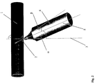
- Fig. 2 The position of the tool 4 and that of the tool 4 during a machining cycle Track are illustrated in Fig. 2.
- the tool 4 the longitudinal axis 5 of the tool angle relative to the perpendicular 3 of the opening 2 ⁇ has, after insertion into the breakthrough 2 through the Feed device 12 as shown in Fig. 2 to the left against the edge of the Breakthrough 2 performed, the tapered end of the tool inside the Pipe section moved under the edge of the opening.
- the direction of movement of the Tool 4 against the edge of the opening 2 is such that after the impact of the tool 4 on the edge of the opening 2, the tip of the tool 4 in Cavity of the pipe section at the beginning partly through the workpiece jacket, after which Reaching the circular contour is completely covered by the outer surface.
- the tool 4 becomes parallel by means of the other feed device 11 to the straight line on which it is moving when it is introduced into the opening 2 this moves out, pulling the material out with it.
- the tool 4 is rotationally symmetrical and, according to the example, has a cylindrical clamping pin.
- the outer surface of the tool in the example is also in the front tapered area slightly curved. The cheapest course this free form - it can also be a truncated cone - depends on the Material and geometric sizes of the workpiece or the fittings to be manufactured.
- the tool 4 experiences at Driving out of the opening 2 no directed against the edge of the opening 2 Feed more.
- the wall thickness of the processing pipe section and the shape and size of the pipe outlet to be produced can, however, from the tool 4 at the second necking station 8 'while his exit from breakthrough 2, at the same time one against the edge of the Breakthrough 2 directional feed movement can be performed. That way it is For example, it is also possible to create a pipe outlet that widens outwards.
- the tool setting angle ⁇ i.e. the angle at which the The longitudinal axis 5 of the tool is inclined against the perpendicular 3 of the opening 2, be enlarged somewhat from the first to the second stage.
- the tool 4 experiences at both necking stations 8, 8 'during moving out of the opening 2 no further radial feed Direction.
- the feeds remain unchanged at both stations.
- the division of the Aushalsens on two process stages also the implementation of one for the run a large number of workpieces to be machined one after the other at favorable cycle times.
Landscapes
- Engineering & Computer Science (AREA)
- Mechanical Engineering (AREA)
- Shaping Metal By Deep-Drawing, Or The Like (AREA)
- Mutual Connection Of Rods And Tubes (AREA)
- Exhaust Silencers (AREA)
Abstract
Description
| Zyklen | 8 |
| Werkzeugwinkel | 8° |
| Werkzeugeinstellwinkel | 13° |
| Vorschub | 0,5 mm in axial, 5 mm radial der auszuhalsenden Kontur |
| Drehzahl des | |
| rotierenden Werkstücks | 120 min-1 |
| Zyklen | 3 |
| Werkzeugwinkel | 8° |
| Werkzeugeinstellwinkel | 13° |
| Vorschub | 0,5 mm in axial, 5 mm radial der auszuhalsenden Kontur |
| Drehzahl des rotierenden Werkstücks | 120 min-1 |
- 1
- Werkstück
- 2
- Durchbruch, Rund- oder Langloch
- 3
- Mittelsenkrechte
- 4
- Werkzeug, Dorn
- 5
- Längsachse
- 6
- Arbeitsstation
- 7
- Arbeitsstation
- 8, 8'
- Arbeitsstation
- 9
- Arbeitsstation
- 10
- Werkstückaufnahme
- 11, 11'
- Vorschubeinrichtung
- 12, 12'
- Vorschubeinrichtung
Claims (15)
- Verfahren zur Erzeugung von Rohrabgängen, vorzugsweise für die Herstellung von Fittings aus metallischen, insbesondere aus Stahl bestehenden Rohrabschnitten, bei dem in die Mantelfläche eines Rohrabschnitts ein als Rund- oder Langloch ausgebildeter Durchbruch eingebracht wird, welcher anschließend mittels eines rotationssymmetrischen, sich an seinem Ende konisch verjüngenden sowie drehbar gelagerten Werkzeugs ausgehalst wird, indem das Werkzeug in einem sich mehrfach wiederholenden Zyklus bei um die Mittelsenkrechte des Durchbruchs rotierendem Werkstück zunächst berührungslos mit einem leicht gegen die Mittelsenkrechte des Durchbruchs geneigten Werkzeugeinstellwinkel in den Durchbruch hineingeführt, anschließend unter Beibehaltung des gewählten Werkzeugeinstellwinkels gegen den Rand des Durchbruchs, den Rand berührend und sich mit dem Ende unter den Rand bewegend, verfahren und dann allmählich bei immer noch gleichem Werkzeugeinstellwinkel mit einem vorgegebenen Vorschub wieder aus dem Durchbruch herausbewegt wird, wobei das nicht selbst getriebene Werkzeug bei der Berührung an dem Rand des Durchbruchs abrollt.
- Verfahren nach Anspruch 1, dadurch gekennzeichnet, dass der auszuhalsende Durchbruch als ein Langloch ausgebildet wird, dessen längere Achse mit der Längsachse des mit dem Rohrabgang zu versehenden Rohrabschnitts zusammenfällt.
- Verfahren nach Anspruch 1, dadurch gekennzeichnet, dass der auszuhalsende Durchbruch als ein Langloch ausgebildet wird, dessen längere Achse in einem leichten Winkel gegen die Längsachse des mit dem Rohrabgang zu versehenden Rohrabschnitts geneigt ist.
- Verfahren nach einem der Ansprüche 1 bis 3, dadurch gekennzeichnet, dass das Aushalsen des Durchbruchs in Abhängigkeit des Materials und der Materialstärke des mit dem Rohrabgang zu versehenden Rohrabschnitts jeweils unter Verwendung des gleichen Werkzeugs in 3 bis 8 Zyklen erfolgt.
- Verfahren nach einem der Ansprüche 1 bis 4, dadurch gekennzeichnet, dass das Aushalsen in mehreren Stufen mit jeweils mehreren Zyklen erfolgt, wobei die Vorschubgeschwindigkeit beim Herausbewegen des Werkzeugs aus dem Durchbruch von einer zur nächsten Stufe beibehalten oder verringert wird.
- Verfahren nach Anspruch 5, dadurch gekennzeichnet, dass das stufenweise Aushalsen unter Verwendung hinsichtlich ihrer geometrischen Abmessungen gleicher Werkzeuge erfolgt, wobei insbesondere der Werkzeugwinkel, mit welchem sich das Werkzeug an seinem Ende verjüngt, von einer Stufe zur nächsten unverändert bleibt.
- Verfahren nach Anspruch 5 oder 6, dadurch gekennzeichnet, dass der Werkzeugeinstellwinkel, in welchem das Werkzeug gegen die Mittelsenkrechte des Durchbruchs geneigt ist, von einer Stufe zur nächsten unverändert bleibt.
- Verfahren nach Anspruch 5 oder 6, dadurch gekennzeichnet, dass der Werkzeugeinstellwinkel, in welchem das Werkzeug gegen die Mittelsenkrechte des Durchbruchs geneigt ist, von einer Stufe zur nächsten geringfügig vergrößert wird.
- Verfahren nach einem der Ansprüche 5 bis 8, dadurch gekennzeichnet, dass das Aushalsen zweistufig erfolgt, wobei in der zweiten Stufe das Herausbewegen des Werkzeugs aus dem Durchbruch unter gleichzeitig weiterem Vorschub gegen den Rand des Durchbruchs erfolgt.
- Verfahren nach einem der Ansprüche 1 bis 9, dadurch gekennzeichnet, dass das Werkzeug während des Aushalsens auf einer kartesischen Bahn geführt wird, nämlich zunächst berührungslos mit einem leicht gegen die Mittelsenkrechte des Durchbruchs geneigten Werkzeugeinstellwinkel in den Durchbruch hinein und dann im rechten Winkel dazu gegen den Rand des Durchbruchs.
- Verfahren nach einem der Ansprüche 1 bis 10, dadurch gekennzeichnet, dass sich dem Aushalsen ein Planfräsen zum Entgraten und Glätten der Kante des erzeugten Rohrabgangs anschließt.
- Vorrichtung zur Erzeugung von Rohrabgängen, vorzugsweise für die Herstellung von Fittings aus metallischen, insbesondere aus Stahl bestehenden Rohrabschnitten, welche als eine Maschine in Form eines Karussells mit wenigstens vier Arbeitsstationen (6, 7, 8, 8', 9) ausgebildet ist, von denen eine (6) der Beschickung und Entnahme mit bzw. von Werkstücken (1), eine (7) der Einbringung eines Rund-oder Langlochs (2) in die Mantelfläche als Rohrabschnitt ausgebildeter Werkstücke (1), mindestens eine (8, 8') der Aushalsung eines in ein Werkstück (1) eingebrachten Rund- oder Langlochs (2) sowie eine (9) dem Planfräsen der Abschlusskante einer erzeugten Aushalsung dient, wobei zur Aufnahme rohrförmiger Werkstücke (1) mindestens eine Werkstückaufnahme (10) vorgesehen ist, mittels welcher ein Werkstück (1) für die gesamte Dauer der Bearbeitung einspannbar und an den zur Aushalsung dienenden Arbeitsstationen (8, 8') in eine Rotationsbewegung um die Mittelsenkrechte (3) des zuvor erzeugten Durchbruchs (2) versetzbar ist und wobei das Aushalsen des in das Werkstück (1) eingebrachten Durchbruchs (2) mit einem Werkzeug (4) erfolgt, welches als ein rotationssymmetrischer, sich an seinem Ende konisch verjüngender Dorn mit glatter Oberfläche ausgebildet ist, dessen Längsachse (5) in einem Werkzeugeinstellwinkel (α) leicht gegen die Mittelsenkrechte (3) des Durchbruchs (2) geneigt ist und der mittels dafür an den entsprechenden Arbeitsstationen (8, 8') vorgesehener Vorschubeinrichtungen (11, 11', 12, 12') mit einer vorgebbaren Vorschubgeschwindigkeit sowohl axial als auch radial zu der am Werkstück (1) auszuhalsenden Kontur bewegbar ist.
- Vorrichtung nach Anspruch 12, dadurch gekennzeichnet, dass die Maschine zwei dem Aushalsen des Durchbruchs (2) dienende Arbeitsstationen (8; 8') aufweist.
- Vorrichtung nach Anspruch 12 oder 13, dadurch gekennzeichnet, dass der Werkzeugwinkel (β), in welchem sich der zum Aushalsen verwendete Dorn an seinem Ende verjüngt, 6° bis 10° beträgt.
- Vorrichtung nach einem der Ansprüche 12 bis 14, dadurch gekennzeichnet, dass der Werkzeugeinstellwinkel (α) variierbar, aber vorzugsweise etwa doppelt so groß wie der Werkzeugwinkel (β) ist.
Applications Claiming Priority (2)
| Application Number | Priority Date | Filing Date | Title |
|---|---|---|---|
| DE10032810 | 2000-06-30 | ||
| DE10032810A DE10032810C2 (de) | 2000-06-30 | 2000-06-30 | Verfahren zur Erzeugung von Rohrabgängen, vorzugsweise für die Herstellung von Fittings aus metallischen Rohrabschnitten und hierfür geeignete Vorrichtung |
Publications (2)
| Publication Number | Publication Date |
|---|---|
| EP1166909A1 true EP1166909A1 (de) | 2002-01-02 |
| EP1166909B1 EP1166909B1 (de) | 2004-08-25 |
Family
ID=7647967
Family Applications (1)
| Application Number | Title | Priority Date | Filing Date |
|---|---|---|---|
| EP01250246A Expired - Lifetime EP1166909B1 (de) | 2000-06-30 | 2001-06-28 | Verfahren zur Erzeugung von Rohrabgängen, vorzugsweise für die Herstellung von Fittings aus metallischen Rohrabschnitten und hierfür geeignete Vorrichtung |
Country Status (3)
| Country | Link |
|---|---|
| EP (1) | EP1166909B1 (de) |
| AT (1) | ATE274380T1 (de) |
| DE (2) | DE10032810C2 (de) |
Cited By (2)
| Publication number | Priority date | Publication date | Assignee | Title |
|---|---|---|---|---|
| WO2019228597A1 (de) | 2018-05-29 | 2019-12-05 | ATG Automations-Technik Gröditz GmbH & Co. KG | Erzeugung eines abgangs an einem hohlkörper |
| CN113680868A (zh) * | 2021-07-21 | 2021-11-23 | 王帆 | 一种铝管弯折仪 |
Citations (5)
| Publication number | Priority date | Publication date | Assignee | Title |
|---|---|---|---|---|
| US3151657A (en) * | 1961-03-22 | 1964-10-06 | United Sheet Metal Co Inc | Sheet metal forming machines |
| EP0007871A1 (de) * | 1978-07-28 | 1980-02-06 | ATELIERS ET CHANTIERS DE BRETAGNE ACB Société anonyme dite: | Maschine für das Heissausführen von Kragen in gewölbten Böden |
| SU1310077A1 (ru) * | 1985-10-18 | 1987-05-15 | Ленинградский Политехнический Институт Им.М.И.Калинина | Способ изготовлени цилиндрических изделий |
| JPH0796332A (ja) * | 1993-09-29 | 1995-04-11 | Sango Co Ltd | 管のバーリング加工方法及びバーリング加工装置 |
| EP0752289A2 (de) * | 1995-06-05 | 1997-01-08 | Enami Seiki Mfg. Co., Ltd. | Werkzeug zum Formen eines Abzweigrohres und Verfahren zur Herstellung einer Abzweigrohrleitung an einem metallischen Rohr |
Family Cites Families (3)
| Publication number | Priority date | Publication date | Assignee | Title |
|---|---|---|---|---|
| US656425A (en) * | 1899-10-02 | 1900-08-21 | Fritz Schilling | Apparatus for enlarging ajutages of metal tubes. |
| FI800278A7 (fi) * | 1980-01-30 | 1981-01-01 | Serlachius Oy | Kaulustusporalaite. |
| NL8104774A (nl) * | 1981-10-21 | 1983-05-16 | Drabus Bv | Vloeiboor. |
-
2000
- 2000-06-30 DE DE10032810A patent/DE10032810C2/de not_active Expired - Fee Related
-
2001
- 2001-06-28 AT AT01250246T patent/ATE274380T1/de not_active IP Right Cessation
- 2001-06-28 DE DE50103373T patent/DE50103373D1/de not_active Expired - Fee Related
- 2001-06-28 EP EP01250246A patent/EP1166909B1/de not_active Expired - Lifetime
Patent Citations (5)
| Publication number | Priority date | Publication date | Assignee | Title |
|---|---|---|---|---|
| US3151657A (en) * | 1961-03-22 | 1964-10-06 | United Sheet Metal Co Inc | Sheet metal forming machines |
| EP0007871A1 (de) * | 1978-07-28 | 1980-02-06 | ATELIERS ET CHANTIERS DE BRETAGNE ACB Société anonyme dite: | Maschine für das Heissausführen von Kragen in gewölbten Böden |
| SU1310077A1 (ru) * | 1985-10-18 | 1987-05-15 | Ленинградский Политехнический Институт Им.М.И.Калинина | Способ изготовлени цилиндрических изделий |
| JPH0796332A (ja) * | 1993-09-29 | 1995-04-11 | Sango Co Ltd | 管のバーリング加工方法及びバーリング加工装置 |
| EP0752289A2 (de) * | 1995-06-05 | 1997-01-08 | Enami Seiki Mfg. Co., Ltd. | Werkzeug zum Formen eines Abzweigrohres und Verfahren zur Herstellung einer Abzweigrohrleitung an einem metallischen Rohr |
Cited By (3)
| Publication number | Priority date | Publication date | Assignee | Title |
|---|---|---|---|---|
| WO2019228597A1 (de) | 2018-05-29 | 2019-12-05 | ATG Automations-Technik Gröditz GmbH & Co. KG | Erzeugung eines abgangs an einem hohlkörper |
| CN113680868A (zh) * | 2021-07-21 | 2021-11-23 | 王帆 | 一种铝管弯折仪 |
| CN113680868B (zh) * | 2021-07-21 | 2024-05-03 | 淮北徽鼎铝业有限公司 | 一种铝管弯折仪 |
Also Published As
| Publication number | Publication date |
|---|---|
| DE50103373D1 (de) | 2004-09-30 |
| EP1166909B1 (de) | 2004-08-25 |
| DE10032810A1 (de) | 2002-01-17 |
| DE10032810C2 (de) | 2003-12-04 |
| ATE274380T1 (de) | 2004-09-15 |
Similar Documents
| Publication | Publication Date | Title |
|---|---|---|
| EP2127777A1 (de) | Vorrichtung und Verfahren zum Herstellen oder Bearbeiten von Werkstücken aus einer Vorform, insbesondere zum Anformen von Innenprofilen oder Innenverzahnungen | |
| DE3805814A1 (de) | Verfahren und vorrichtung zur schaffung eines im wesentlichen rechtwinkligen boerdelrandes an rohren | |
| EP3645188B1 (de) | Verfahren zur herstellung eines biegeteils und biegemaschine zur durchführung des verfahrens | |
| EP2279819A2 (de) | Vorrichtung zum mechanischen Bearbeiten von rohr- oder stangenförmigen Werkstücken | |
| EP1982777A1 (de) | Durchlaufschweissmaschine zum Verschweissen eines Rohrrohlings | |
| DE19816403A1 (de) | Vorrichtung zum Formen von Draht, mit einer Drahtbremseinrichtung | |
| DE19725453C2 (de) | Verfahren zur Herstellung einer Hohlwelle | |
| DE2808081A1 (de) | Verfahren und vorrichtung zum herstellen wendelfoermiger rotorrohlinge fuer exzenterschneckenpumpen | |
| DE10032810C2 (de) | Verfahren zur Erzeugung von Rohrabgängen, vorzugsweise für die Herstellung von Fittings aus metallischen Rohrabschnitten und hierfür geeignete Vorrichtung | |
| DE2512854C3 (de) | Verfahren zum Herstellen von Wendelbohrern o.ä. Werkzeugen | |
| DE102010041164B4 (de) | Verfahren zum Herstellen eines Bohrers | |
| EP3639946A1 (de) | Verbindungselement, verfahren und vorrichtung zu seiner herstellung | |
| DE102010031607C5 (de) | Gleitflächenbearbeitung einer elastisch verformten Gleitlagerschale | |
| EP0683000A1 (de) | Vorrichtung zum spanenden Oberflächenbearbeiten | |
| DE647719C (de) | Walzenkalibrierung | |
| DE102006029637B4 (de) | Verfahren und Vorrichtung zum Biegen eines zylinderförmigen Werkstücks | |
| EP3801944B1 (de) | Erzeugung eines abgangs an einem hohlkörper | |
| DE19648971A1 (de) | Bohrer sowie Verfahren zu seiner Herstellung | |
| DE102008006293A1 (de) | Verfahren und Vorrichtung zum Biegen von Rundrohren und Profilen | |
| EP1419840A1 (de) | Vorrichtung zum Bearbeiten, insbesondere Schaben der Ränder von Bandmaterial sowie Verfahren zum Laserschweissen | |
| WO2011120063A1 (de) | Vorrichtung zum trennen langgestreckter werkstücke | |
| DE1866721U (de) | Vorrichtung zum stanzen bzw. lochen von hohlkoerpern, vornehmlich von rohren. | |
| DE4424822A1 (de) | Verfahren und Vorrichtung zum Erzeugen eines Profils an einem Werkstück | |
| EP4126409A1 (de) | Biegemaschine | |
| DE102018208020A1 (de) | Verfahren zum Erzeugen einer Öffnung in einem Hohlkörper |
Legal Events
| Date | Code | Title | Description |
|---|---|---|---|
| PUAI | Public reference made under article 153(3) epc to a published international application that has entered the european phase |
Free format text: ORIGINAL CODE: 0009012 |
|
| AK | Designated contracting states |
Kind code of ref document: A1 Designated state(s): AT BE CH CY DE DK ES FI FR GB GR IE IT LI LU MC NL PT SE TR |
|
| AX | Request for extension of the european patent |
Free format text: AL;LT;LV;MK;RO;SI |
|
| RAP1 | Party data changed (applicant data changed or rights of an application transferred) |
Owner name: SMB INNOVATIVE PRODUKTE WILDAU GMBH |
|
| 17P | Request for examination filed |
Effective date: 20020626 |
|
| AKX | Designation fees paid |
Free format text: AT BE CH CY DE DK ES FI FR GB GR IE IT LI LU MC NL PT SE TR |
|
| 17Q | First examination report despatched |
Effective date: 20030526 |
|
| GRAP | Despatch of communication of intention to grant a patent |
Free format text: ORIGINAL CODE: EPIDOSNIGR1 |
|
| GRAS | Grant fee paid |
Free format text: ORIGINAL CODE: EPIDOSNIGR3 |
|
| GRAA | (expected) grant |
Free format text: ORIGINAL CODE: 0009210 |
|
| AK | Designated contracting states |
Kind code of ref document: B1 Designated state(s): AT BE CH CY DE DK ES FI FR GB GR IE IT LI LU MC NL PT SE TR |
|
| PG25 | Lapsed in a contracting state [announced via postgrant information from national office to epo] |
Ref country code: IT Free format text: LAPSE BECAUSE OF FAILURE TO SUBMIT A TRANSLATION OF THE DESCRIPTION OR TO PAY THE FEE WITHIN THE PRESCRIBED TIME-LIMIT;WARNING: LAPSES OF ITALIAN PATENTS WITH EFFECTIVE DATE BEFORE 2007 MAY HAVE OCCURRED AT ANY TIME BEFORE 2007. THE CORRECT EFFECTIVE DATE MAY BE DIFFERENT FROM THE ONE RECORDED. Effective date: 20040825 Ref country code: TR Free format text: LAPSE BECAUSE OF FAILURE TO SUBMIT A TRANSLATION OF THE DESCRIPTION OR TO PAY THE FEE WITHIN THE PRESCRIBED TIME-LIMIT Effective date: 20040825 Ref country code: IE Free format text: LAPSE BECAUSE OF FAILURE TO SUBMIT A TRANSLATION OF THE DESCRIPTION OR TO PAY THE FEE WITHIN THE PRESCRIBED TIME-LIMIT Effective date: 20040825 Ref country code: NL Free format text: LAPSE BECAUSE OF FAILURE TO SUBMIT A TRANSLATION OF THE DESCRIPTION OR TO PAY THE FEE WITHIN THE PRESCRIBED TIME-LIMIT Effective date: 20040825 Ref country code: FR Free format text: LAPSE BECAUSE OF FAILURE TO SUBMIT A TRANSLATION OF THE DESCRIPTION OR TO PAY THE FEE WITHIN THE PRESCRIBED TIME-LIMIT Effective date: 20040825 Ref country code: FI Free format text: LAPSE BECAUSE OF FAILURE TO SUBMIT A TRANSLATION OF THE DESCRIPTION OR TO PAY THE FEE WITHIN THE PRESCRIBED TIME-LIMIT Effective date: 20040825 Ref country code: GB Free format text: LAPSE BECAUSE OF FAILURE TO SUBMIT A TRANSLATION OF THE DESCRIPTION OR TO PAY THE FEE WITHIN THE PRESCRIBED TIME-LIMIT Effective date: 20040825 |
|
| REG | Reference to a national code |
Ref country code: GB Ref legal event code: FG4D Free format text: NOT ENGLISH |
|
| RIN1 | Information on inventor provided before grant (corrected) |
Inventor name: KEIL, ULRICH. Inventor name: DROMMER, ROLAND Inventor name: ENGELMANN, ROLF |
|
| REG | Reference to a national code |
Ref country code: CH Ref legal event code: EP |
|
| REG | Reference to a national code |
Ref country code: IE Ref legal event code: FG4D Free format text: GERMAN |
|
| REF | Corresponds to: |
Ref document number: 50103373 Country of ref document: DE Date of ref document: 20040930 Kind code of ref document: P |
|
| PG25 | Lapsed in a contracting state [announced via postgrant information from national office to epo] |
Ref country code: DK Free format text: LAPSE BECAUSE OF FAILURE TO SUBMIT A TRANSLATION OF THE DESCRIPTION OR TO PAY THE FEE WITHIN THE PRESCRIBED TIME-LIMIT Effective date: 20041125 Ref country code: GR Free format text: LAPSE BECAUSE OF FAILURE TO SUBMIT A TRANSLATION OF THE DESCRIPTION OR TO PAY THE FEE WITHIN THE PRESCRIBED TIME-LIMIT Effective date: 20041125 Ref country code: SE Free format text: LAPSE BECAUSE OF FAILURE TO SUBMIT A TRANSLATION OF THE DESCRIPTION OR TO PAY THE FEE WITHIN THE PRESCRIBED TIME-LIMIT Effective date: 20041125 |
|
| PG25 | Lapsed in a contracting state [announced via postgrant information from national office to epo] |
Ref country code: ES Free format text: LAPSE BECAUSE OF FAILURE TO SUBMIT A TRANSLATION OF THE DESCRIPTION OR TO PAY THE FEE WITHIN THE PRESCRIBED TIME-LIMIT Effective date: 20041206 |
|
| NLV1 | Nl: lapsed or annulled due to failure to fulfill the requirements of art. 29p and 29m of the patents act | ||
| GBV | Gb: ep patent (uk) treated as always having been void in accordance with gb section 77(7)/1977 [no translation filed] |
Effective date: 20040825 |
|
| REG | Reference to a national code |
Ref country code: IE Ref legal event code: FD4D |
|
| PG25 | Lapsed in a contracting state [announced via postgrant information from national office to epo] |
Ref country code: AT Free format text: LAPSE BECAUSE OF NON-PAYMENT OF DUE FEES Effective date: 20050628 Ref country code: LU Free format text: LAPSE BECAUSE OF NON-PAYMENT OF DUE FEES Effective date: 20050628 Ref country code: CY Free format text: LAPSE BECAUSE OF FAILURE TO SUBMIT A TRANSLATION OF THE DESCRIPTION OR TO PAY THE FEE WITHIN THE PRESCRIBED TIME-LIMIT Effective date: 20050628 |
|
| PG25 | Lapsed in a contracting state [announced via postgrant information from national office to epo] |
Ref country code: LI Free format text: LAPSE BECAUSE OF NON-PAYMENT OF DUE FEES Effective date: 20050630 Ref country code: MC Free format text: LAPSE BECAUSE OF NON-PAYMENT OF DUE FEES Effective date: 20050630 Ref country code: BE Free format text: LAPSE BECAUSE OF NON-PAYMENT OF DUE FEES Effective date: 20050630 Ref country code: CH Free format text: LAPSE BECAUSE OF NON-PAYMENT OF DUE FEES Effective date: 20050630 |
|
| PLBE | No opposition filed within time limit |
Free format text: ORIGINAL CODE: 0009261 |
|
| STAA | Information on the status of an ep patent application or granted ep patent |
Free format text: STATUS: NO OPPOSITION FILED WITHIN TIME LIMIT |
|
| 26N | No opposition filed |
Effective date: 20050526 |
|
| EN | Fr: translation not filed | ||
| PG25 | Lapsed in a contracting state [announced via postgrant information from national office to epo] |
Ref country code: DE Free format text: LAPSE BECAUSE OF NON-PAYMENT OF DUE FEES Effective date: 20060103 |
|
| REG | Reference to a national code |
Ref country code: CH Ref legal event code: PL |
|
| BERE | Be: lapsed |
Owner name: *SMB INNOVATIVE PRODUKTE WILDAU G.M.B.H. Effective date: 20050630 |
|
| PG25 | Lapsed in a contracting state [announced via postgrant information from national office to epo] |
Ref country code: PT Free format text: LAPSE BECAUSE OF NON-PAYMENT OF DUE FEES Effective date: 20050125 |