EP1166978B1 - Maschine zur Herstellung von Kunststoffbeuteln - Google Patents
Maschine zur Herstellung von Kunststoffbeuteln Download PDFInfo
- Publication number
- EP1166978B1 EP1166978B1 EP01250215A EP01250215A EP1166978B1 EP 1166978 B1 EP1166978 B1 EP 1166978B1 EP 01250215 A EP01250215 A EP 01250215A EP 01250215 A EP01250215 A EP 01250215A EP 1166978 B1 EP1166978 B1 EP 1166978B1
- Authority
- EP
- European Patent Office
- Prior art keywords
- waste
- torn
- pulled
- station
- rotating members
- Prior art date
- Legal status (The legal status is an assumption and is not a legal conclusion. Google has not performed a legal analysis and makes no representation as to the accuracy of the status listed.)
- Expired - Lifetime
Links
- 239000004033 plastic Substances 0.000 title claims abstract description 43
- 239000002699 waste material Substances 0.000 claims abstract description 220
- 239000000463 material Substances 0.000 claims abstract description 165
- 238000011144 upstream manufacturing Methods 0.000 claims abstract description 48
- 239000002985 plastic film Substances 0.000 claims abstract description 7
- 229920006255 plastic film Polymers 0.000 claims abstract description 7
- JOYRKODLDBILNP-UHFFFAOYSA-N Ethyl urethane Chemical compound CCOC(N)=O JOYRKODLDBILNP-UHFFFAOYSA-N 0.000 description 5
- 229920001971 elastomer Polymers 0.000 description 5
- 239000005060 rubber Substances 0.000 description 5
- 230000005611 electricity Effects 0.000 description 2
- 238000004519 manufacturing process Methods 0.000 description 2
- 230000003068 static effect Effects 0.000 description 2
- 208000037805 labour Diseases 0.000 description 1
Images


Classifications
-
- B—PERFORMING OPERATIONS; TRANSPORTING
- B26—HAND CUTTING TOOLS; CUTTING; SEVERING
- B26F—PERFORATING; PUNCHING; CUTTING-OUT; STAMPING-OUT; SEVERING BY MEANS OTHER THAN CUTTING
- B26F3/00—Severing by means other than cutting; Apparatus therefor
- B26F3/002—Precutting and tensioning or breaking
-
- B—PERFORMING OPERATIONS; TRANSPORTING
- B26—HAND CUTTING TOOLS; CUTTING; SEVERING
- B26D—CUTTING; DETAILS COMMON TO MACHINES FOR PERFORATING, PUNCHING, CUTTING-OUT, STAMPING-OUT OR SEVERING
- B26D7/00—Details of apparatus for cutting, cutting-out, stamping-out, punching, perforating, or severing by means other than cutting
- B26D7/18—Means for removing cut-out material or waste
- B26D7/1827—Means for removing cut-out material or waste by tearing
Definitions
- the invention relates to an apparatus according to the preambles of claims 1 and 13 for making plastic bags.
- An example of such a device is shown in JP9295625A.
- the apparatus includes feeding means by which the material 4 is intermittently fed for a length along a longitudinal feeding path.
- the material 4 is heat sealed by heat seal means longitudinally and widthwise of the material 4 whenever intermittently fed and temporarily stopped so that heat sealed portions 5 can be formed longitudinally and widthwise of the material 4.
- the material 4 may be slitted by slitting means along a slit line 6.
- the apparatus is arranged to successively make plastic bags 2 with wastes 8.
- Each of the wastes 8 has upstream and downstream edges 10 and 12.
- the material 4 is totally cut by suitable cutting means along the upstream and downstream edges 10 and 12 of waste 8 whenever intermittently fed and temporarily stopped.
- the wastes 8 are therefore brought into existence one by one or two by two by making shaped bags 2.
- the waste 8 may be called a waste material or scrap.
- a hole is usually formed under the feeding path of material so that the wastes can be dropped down through the hole to be removed.
- the wastes 8 can neither always be dropped down nor removed even if the material 4 is totally cut.
- the plastic bags 2 and the wastes 8 may adhere to each other by reason of certain factor such as static electricity, to be fed as they are.
- the wastes 8 must therefore be removed later and manually by operator from the plastic bags 2, taking labours and times.
- the hole through which the wastes 8 are dropped down it is required to change the size of hole when changing the size of plastic bag 2 and waste 8.
- JP 2000 190403 A which was published an July 11, 2000, discloses an apparatus for making plastic bags from a web material comprising two or more layers of plastic film, said apparatus including feeding means by which said material is intermittently fed for a length along a longitudinal feeding path, to successively make plastic bags with wastes, each of said wastes having upstream and downstream edges. At first, these are formed micro connections between those parts of the web material which forms the plastic bags and the wastes, and thereafter the wastes are torn off.
- the apparatus including feeding means by which the material is intermittently fed for a length along a longitudinal feeding path, to successively make plastic bags with wastes, each of the wastes having upstream and downstream edges.
- Another object of the invention is to provide the apparatus in which the wastes can be removed automatically and reliably, without adhering to the plastic bags.
- the partially cutting means comprises Thomson blade means opposed to the material.
- the partially cutting means may further comprise drive means by which the Thomson blade means is moved toward the material so that the material can be partially cut by the Thomson blade means along the upstream and downstream edges of waste.
- the Thomson blade means has micro depressions formed and spaced from each other along the cutting edge thereof to leave micro joints formed and spaced from each other along the upstream and downstream edges of waste.
- the micro joints make the material partially cut. The material and the waste are kept connected with each other by the micro joints.
- the material is partially cut by the partially cutting means to be pulled and torn more easily at the downstream edge than at the upstream edge of waste.
- the material is first pulled and torn by the discharge means from the downstream edge of waste after the waste reaches the second station and the material reaches the third station.
- the waste is then pulled and torn by the waste removing means from the upstream edge of waste.
- the waste removing means comprises upper and lower rotating members disposed on upper and lower sides of the feeding path.
- the waste removing means further comprises drive means by which at least one of the upper and lower rotating members is moved toward the waste so that the waste can be sandwiched between the upper and lower rotating members.
- the waste removing means may comprise drive means by which at least one of the upper and lower rotating members is rotated at a considerable speed so that the waste can be pulled and torn by the upper and lower rotating members.
- the discharge means advantageously comprises upper and lower belts between which the material is directed and sandwiched to be pulled and torn by the upper and lower belts.
- the waste may be held by the waste removing means after reaching the second station so that the material can be pulled and torn by the discharge means from the downstream edge of waste. The waste is then pulled and torn by the waste removing means from the upstream edge of waste.
- the waste removing means may comprise drive means by which at least one of the upper and lower rotating members is moved toward the waste so that the waste can be sandwiched between and held by the upper and lower rotating members after reaching the second station.
- the waste removing means may comprise upper and lower fingers disposed on upper and lower sides of the feeding path.
- the waste removing means may further comprise drive means by which at least one of the upper and lower fingers is moved toward the waste so that the waste can be sandwiched between and held by the upper and lower fingers after reaching the second station.
- the waste removing means preferably comprises drive means by which the upper and lower fingers are moved in a direction so that the waste can be pulled and torn by the upper and lower fingers.
- the discharge means comprises drive means by which the upper and lower belts are driven at a first speed.
- the waste removing means comprises drive means by which at least one of the upper and lower rotating members is moved toward the waste so that the waste can be sandwiched between the upper and lower rotating members at the same time as the material is sandwiched between the upper and lower belts.
- the waste removing means further comprises drive means by which at least one of the upper and lower rotating members is rotated at a second speed lower than the first speed so that the material is pulled and torn by the upper and lower belts, while the waste is pulled and torn by the upper and lower rotating members, by means of a difference in speed between the upper and lower belts and the upper and lower rotating members.
- the partially cutting means of claim 13 preferably comprises drive means by which the Thomson blade means is moved toward the material so that the material can be partially cut by the Thomson blade means along the upstream edge of waste.
- the optional micro joints of claim 15 make the material partially cut.
- the waste is kept connected with the material by the micro joints.
- the optional discharge means of claim 16 comprises upper and lower belts, the material being directed and sandwiched between the upper and lower belts to be discharged by the upper and lower belts.
- the waste is then directed and sandwiched between the upper and lower belts to be pulled, torn and removed by the upper and lower belts.
- Stop means is incorporated into the upper and lower belts so that the waste can strike against the stop means for dropping from the upper and lower belts.
- Fig. 1 illustrates an apparatus for making plastic bags 2 from a web material 4 comprising two or more layers of plastic film, according to the invention.
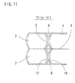
- Each of the plastic bags 2 comprises a shaped bag having opposite sides curved convexly or concavely, as in the case of the apparatus of Fig. 11.
- the apparatus includes feeding means by which the material 4 is intermittently fed for a length along a longitudinal feeding path, to successively make plastic bags 2 with wastes 8.
- Each of the wastes 8 has upstream and downstream edges 10 and 12.
- the feeding means comprises upper and lower rollers 14 between which the material 4 is directed and sandwiched.
- the upper and lower rollers 14 are rotated by drive means such as a servo motor so that the material 4 can be intermittently fed for a length.
- the material 4 is heat sealed by heat seal means 16 longitudinally and widthwise of the material 4 whenever intermittently fed and temporarily stopped so that heat sealed portions 5 can be formed longitudinally and widthwise of the material 4.
- the material 4 is slitted by slitting means along a slit line 6, as in the case of the apparatus of Fig. 11.
- the apparatus further includes partially cutting means disposed at a first station predetermined along the feeding path of material 4.
- the material 4 is partially cut by the partially cutting means along the upstream and downstream edges 10 and 12 of waste 8 whenever intermittently fed and temporarily stopped.
- the partially cutting means includes Thomson blade means comprising a pair of Thomson blades 18 and 20 and opposed to the material 4.
- the Thomson blades 18 and 20 are spaced from each other along the feeding path of material 4 and mounted on a carriage 22, the material 4 being directed between the Thomson blades 18 and 20 and a receiver 24.
- the partially cutting means further includes drive means by which the Thomson blades 18 and 20 are moved toward the material 4 whenever the material 4 is intermittently fed and temporarily stopped.
- the drive means comprises a linkage 26 by which the carriage 22 is connected to the heat seal means 16.
- the Thomson blades 18 and 20 and the carriage 22 are therefore moved and lowered by the linkage 26 synchronously with the heat seal means 16 whenever the material 4 is intermittently fed and temporarily stopped so that the material 4 can be sandwiched between the Thomson blades 18 and 20 and the receiver 24 to be partially cut by the Thomson blades 18 and 20 along the upstream and downstream edges 10 and 12 of waste 8.
- each of the Thomson blades 18 and 20 has micro depressions formed and spaced from each other along the cutting edge thereof to leave micro joints 28 and 30 formed and spaced from each other along the upstream and downstream edges 10 and 12 of waste 8, as shown in Fig. 3.
- the micro joints 28 and 30 make the material 4 partially cut.
- the material 4 and the waste 8 are kept connected with each other by the micro joints 28 and 30.
- the micro joints 30 are less in number than the micro joints 28.
- each of the micro joints 28 and 30 has a very small size of about 0.1 mm.
- urethan rubbers 32 are disposed on the opposite sides of each of the Thomson blades 18 and 20 and mounted on the carriage 22, as shown in Fig. 2.
- the urethan rubbers 32 are pressed against the material 4 and the receiver 24 to be elastically deformed so that the material 4 can be held by the urethan rubbers 32 when partially cut by the Thomson blades 18 and 20.
- the carriage 22 and the Thomson blades 18 and 20 are then moved and lifted by the linkage 26 synchronously with the seal means 16 to be retracted from the material 4 and the receiver 24.
- the urethan rubbers 32 are elastically restored to the original state so that the material 4 can be pushed by the urethan rubbers 32 to be separated from the Thomson blades 18 and 20. This prevents the material 4 from adhering to the Thomson blades 18 and 20.
- the material 4 is therefore not pulled upwardly by the Thomson blades 18 and 20.
- the apparatus further includes waste removing means disposed at a second station predetermined downstream of and at a distance from the first station at which the Thomson blades 18 and 20 are disposed.
- the waste 8 reaches the second station when the material 4 is intermittently fed again after partially cut by the Thomson blades 18 and 20, as described later.
- the waste removing means includes upper and lower rotating means comprising upper and lower rollers 34 and 36 and disposed on upper and lower sides of the feeding path of material 4.
- the waste removing means further includes drive means by which at least one of the upper and lower rollers 34 and 36 is moved toward the waste 8.
- the drive means comprises a linkage 38 by which the upper roller 34 is connected to the heat seal means 16, as in the case of the Thomson blades 18 and 20 and the linkage 26.
- the upper roller 34 is therefore moved and lowered by the linkage 38 synchronously with the heat seal means 16 whenever the material 4 is intermittently fed and temporarily stopped.
- the waste removing means includes drive means by which at least one of the upper and lower rollers 34 and 36 is rotated at a considerable speed.
- the drive means comprises a drive motor 40 connected to the lower roller 36.
- the lower roller 36 is rotated by the drive motor 40 counterclockwise in Fig. 1 and at all times.
- the apparatus includes discharge means disposed at a third station predetermined downstream of and at a distance from the second station at which the upper and lower rollers 34 and 36 are disposed.
- the material 4 reaches the third station when intermittently fed again after partially cut by the Thomson blades 18 and 20, as also described later.
- the material 4 is pulled and torn by the discharge means from the downstream edge 12 of waste 8 to be discharged by the discharge means as a plastic bag 2, the waste 8 being pulled, torn and removed by the upper and lower rollers 34 and 36 from the upstream edge 10 of waste 8, after the waste 8 reaches the second station and the material 4 reaches the third station, as also described later.
- the discharge means includes upper and lower belts 42 and 44 between which the material 4 is directed and sandwiched.
- the upper belt 42 is engaged with a pulley 46.
- the discharge means further includes a linkage 48 by which the pulley 46 is connected to the heat seal means 16. The pulley 46 is therefore moved and lowered by the linkage 48 synchronously with the heat seal means 16 whenever the material 4 is intermittently fed and temporarily stopped.
- the discharge means further includes drive means by which the upper and lower belts 42 and 44 are driven at a considerable speed.
- the drive means comprises a drive motor 50 connected to pulleys 52 and 54, the upper and lower belts 42 and 44 being engaged with the pulleys 52 and 54.
- a stop 56 is disposed between the second and third station and on the lower side of the feeding path of material 4.
- the stop 56 is connected by a linkage 58 to the heat seal means 16 to be moved synchronously with the heat seal means 16 whenever the material 4 is intermittently fed.
- the distance corresponds to the length for which the material 4 is intermittently fed.
- the distance between the second station and the third station at which the upper and lower belts 42 and 44 are disposed it also corresponds to the length for which the material 4 is intermittently fed. Accordingly, the waste 8 reaches the second position to be directed between the upper and lower rollers 34 and 36 when the material 4 is intermittently fed again after partially cut by the Thomson blades 18 and 20. The material 4 reaches the third station to be directed between the upper and lower belts 42 and 44 when intermittently fed again after partially cut by the Thomson blades 18 and 20.
- the material 4 is temporarily stopped when the waste 8 reaches the second station and the material 4 reaches the third station.
- the pulley 46 is then moved and lowered by the linkage 48 synchronously with the heat seal means 16 so that the material 4 can be first sandwiched between the upper and lower belts 42 and 44.
- the material 4 is therefore pulled by the upper and lower belts 42 and 44 driven by the drive motor 50.
- the material 4 was partially cut by the Thomson blades 18 and 20 to be pulled and torn more easily at the downstream edge 12 than at the upstream edge 10 cf waste 8 before reaching the second and third stations, as described above.
- the material 4 is first pulled and torn by the upper and lower belts 42 and 44 from the downstream edge 12 of waste 8 after the waste 8 reaches the second station and the material 4 reaches the third station.
- the material 4 is therefore discharged by the upper and lower belts 42 and 44 as a plastic bag 2.
- the upper roller 34 is then moved and lowered by the linkage 38 so that the waste 8 can be sandwiched between the upper and lower rollers 34 and 36.
- the lower roller 36 is rotated by the motor 40 counterclockwise in Fig. 1, as described above, so that the upper roller 34 can be rotated by the lower roller 36 clockwise in Fig. 1 when the waste 8 is sandwiched between them.
- the waste 8 is then pulled and torn by the upper and lower rollers 34 and 36 from the upstream edge 10 of waste 8.
- the stop 56 is moved by the linkage 58 into the feeding path of material 4 at the same time as the upper roller 34 is moved by the linkage 38. The waste 8 is therefore torn and removed by the upper and lower rollers 34 and 36 to strike against the stop 56 for dropping along the stop 56.
- the material 4 is partially cut and intermittently fed again and again, to successively make plastic bags 2 with wastes 8.
- the material 4 is pulled and torn again and again to be discharged as a plastic bag 2.
- the waste 8 is pulled, torn and removed again and again.
- the material 4 is pulled and torn again and again to be discharged as plastic bags 2.
- the wastes 8 are pulled, torn and removed again and again.
- the wastes 8 can be removed automatically and reliably. Unlike the prior art, the plastic bags 2 and the wastes 8 can not adhere to each other by reason of certain factor such as static electricity, to be fed as they are.
- the upper roller 34 may be positioned slightly downstream of the lower roller 36 so that the waste 8 can be sandwiched between the upper and lower rollers 34 and 36 and then torn and removed downstream of and obliquely downward from the upper and lower rollers 34 and 36.
- the waste 8 can strike against the stop 56 which is not moved into the feeding path of material 4. The stop 56 is therefore not always required to be moved.
- the material 4 is intermittently fed for a length which corresponds to the sum of sizes of plastic bag 2 and waste 8.
- the apparatus may include drive means comprising ball screws by which the upper and lower rollers 34 and 36 are moved along the feeding path of material 4 to adjust the distance between the first and second stations when changing the the size of plastic bag 2 and waste 8.
- the apparatus is therefore suitable to change the size of plastic bag 2 and waste 8 without difficulty.
- the upper and lower rollers 34 and 36 may be moved by drive means other than the ball screws.
- the upper roller 34 may be rotated at all times.
- the lower roller 34 may be moved by a linkage so that the waste 8 can be sandwiched between the upper and lower rollers 34 and 36.
- the upper and lower rollers 34 and 36 may be rotated at all times respectively.
- the upper and lower rollers 34 and 36 may be moved by linkages respectively.
- One of the upper and lower rollers 34 and 36 may be rotated not at all times but temporarily.
- the other roller is moved by the linkage while one of the upper and lower rollers is rotated so that the waste 8 can be sandwiched between and pulled and torn by the upper and lower rollers 34 and 36.
- the material 4 may be half cut by the Thomson blades to a depth to be partially cut, along the upstream and downstream edges 10 and 12 of waste 8 so that the material 4 can be pulled and torn by the upper and lower belts 42 and 44 from the downstream edge 12 of waste 8, the waste 8 being pulled and torn by the upper and lower rollers 34 and 36 from the upstream edge 10 of waste 8.
- the material 4 may also be half cut by the Thomson blades to a depth to be partially cut so that it can be pulled and torn more easily at the downstream edge 12 than at the upstream edge 10 of waste 8.
- the material 4 may be partially cut by partially cutting means other than the Thomson blades.
- the apparatus is arranged to successively make plastic bags 2 with wastes 8, as shown in Fig. 4.
- the material 4 may be partially or totally cut by the Thomson blades along cutting lines 59.
- the material 4 may be partially cut by the Thomson blades along the upstream and downstream edges of the waste 8 and pulled and torn by the upper and lower belts 42 and 44 from the downstream edge of waste 8 to be discharged by the upper and lower belts 42 and 44 as a plastic bag 2.
- the waste 8 should be then pulled, torn and removed by the upper and lower rollers 34 and 36 from the upstream edge of waste 8.
- each of the upper and lower rollers 34, 36 may have locally large portions so that the waste 8 can be sandwiched between and pulled, torn and removed by the locally large portions, as shown in Fig. 5.
- the waste removing means may include rotating members other than the upper and lower rollers 34 and 36.
- the waste removing means may include rotating members comprising upper and lower arms 60 and 62, as shown in Fig. 6.
- the upper arm 60 is rotated by drive means clockwise about a pin 64 while the lower arm 62 is rotated by drive means counterclockwise about a pin 66 so that the waste 8 can be sandwiched between and pulled, torn and removed downstream of the upper and lower arms 60 and 62.
- the waste 8 is held by the waste removing means after reaching the second station so that the material 4 can be pulled and torn by the discharge means from the downstream edge 12 of waste 8.
- the waste 8 is then pulled and torn by the waste removing means from the upstream edge 10 of waste 8.
- the waste removing means includes upper and lower rotating member comprising upper and lower rollers 34 and 36 and disposed on the upper and lower sides of the feeding path of material 4.
- the discharge means comprises upper and lower belts 42 and 44, as in the case of the apparatus of Fig. 1.
- the waste removing means further includes drive means by which at least one of the upper and lower rollers 34 and 36 is moved toward the waste 8 so that the waste 8 can be sandwiched between the upper and lower rollers 34 and 36 after reaching the second station.
- the drive means comprises a lever 68 and a linkage by which the upper roller 34 is connected to the heat seal means. The upper roller 34 is therefore moved by the lever 68 and the linkage so that the waste 8 can be sandwiched between the upper and lower rollers 34 and 36.
- the upper and lower rollers 34 and 36 are first kept from being rotated so that the waste 8 can be held by the upper and lower rollers 34 and 36.
- the material 4 can therefore be pulled and torn by the upper and lower belts 42 and 44 from the downstream edge 12 of waste 8 to be discharged. Accordingly, unlike the apparatus of Fig 1, the material 4 has therefore not to be partially cut by the partially cutting means to be pulled and torn more easily at the downstream edge 12 than at the upstream edge 10 of waste 8.
- the waste removing means includes drive means by which at least one of the upper and lower rollers 34 and 36 is rotated at a considerable speed so that the waste 8 can be pulled and torn by the upper and lower rollers 34 and 36.
- the drive means comprises a control 70 connected to a drive motor 72 such as a servo motor which is connected to the lower roller 36.
- the lower roller 36 is rotated by the control 70 and the drive motor 72 counterclockwise in Fig. 7 after the material 4 is torn and discharged.
- the upper roller 34 is therefore rotated by the lower roller 36 clockwise in Fig. 7 so that the waste 8 can be pulled and torn by the upper and lower rollers 34 and 36 from the upstream edge 10 of waste 8 to be removed.
- the drive motor 72 can be controlled by the control 70 to change the speed of the upper and lower rollers 34 and 36.
- the upper and lower rollers 34 and 36 are rotated at a high speed when the waste 8 is pulled and torn.
- the upper and lower rollers 34 and 36 are then decelerated into a low speed before the waste 8 is released from the upper and lower rollers 34 and 36.
- the waste 8 is therefore released and removed slowly.
- the apparatus may include ball screws by which the upper and lower rollers 34 and 36 are moved along the feeding path of material 4 to adjust the distance between the first and second stations when changing the size of plastic bag 2 and waste 8.
- the lower roller 36 may be moved by a linkage so that the waste 8 can be sandwiched between the upper and lower rollers 34 and 36.
- the drive motor 72 may be connected not to the lower roller 36 but to the upper roller 34 so that the upper and lower rollers 34 and 36 can be rotated by the drive motor 72.
- the upper and lower rollers 34 and 36 may be moved by linkages respectively.
- the drive motor 72 may be connected to the upper and lower rollers 34 and 36.
- the waste 8 can be pulled, torn and removed by the upper and lower rollers 34 and 36 of Fig. 7.
- the upper and lower rollers 34 and 36 may have locally large portions, as in the case of those of Fig. 5.
- the waste removing means may comprise rotating members other than the upper and lower rollers 34 and 36.
- the waste removing means includes upper and lower fingers 74 and 76 disposed on upper and lower sides of the feeding path of material 4.
- the waste removing means further includes drive means by which at least one of the upper and lower fingers 74 and 76 is moved toward the waste 8.
- the drive means comprises air cylinders 78 mounted on carriages 80 and connected to the upper and lower fingers 74 and 76. The upper and lower fingers 74 and 76 are moved by the air cylinders 78 so that the waste 8 can be sandwiched between and held by the upper and lower fingers 74 and 76 after reaching the second station at which the upper and lower fingers 74 and 76 are disposed.
- the waste removing means include drive means by which the upper and lower fingers 74 and 76 are moved in a direction in which the material 4 is intermittently fed.
- the drive means comprises air cylinders 82 connected to the carriages 80. The upper and lower fingers 74 and 76 and the carriages 80 are moved by the air cylinders 82 so that the waste 8 can be pulled and torn by the upper and lower fingers 74 and 76.
- the apparatus may include ball screws by which the upper and lower fingers 74 and 76 are moved along the feeding path of material 4 to adjust the distance between the first and second stations when changing the size of plastic bag 2 and waste 8.
- a plurality of upper and lower fingers 74 and 76 may be spaced from each other widthwise of the material 4.
- the upper and lower fingers 74 and 76 may be movable widthwise of the material 4 to change the spaces of upper and lower fingers 74 and 76.
- the waste 8 can be pulled, torn and removed by the upper and lower fingers 74 and 76.
- the discharge means includes the upper and lower belts 42 and 44 shown in Fig. 1.
- the upper and lower belts 42 and 44 are driven at a first speed.
- the waste removing means includes upper and lower rotating members comprising the upper and lower rollers 34 and 36 in Fig. 1, Fig. 4 or Fig. 5. At least one of the upper and lower rollers 34 and 36 is moved toward the waste 8 so that the waste 8 can be sandwiched between the upper and lower rollers 34 and 36 at the same time as the material 4 is sandwiched between the upper and lower belts 42 and 44. In addition, at least one of the upper and lower rollers 34 and 36 is rotated at a second speed lower than the first speed.
- the material 4 is pulled and torn by the upper and lower belts 42 and 44, while the waste 8 is pulled and torn by the upper and lower rollers 34 and 36, by means of a difference in speed between the upper and lower belts 42 and 44 and the upper and lower rollers 34 and 36.
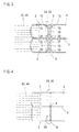
- the apparatus includes partially cutting means combined with totally cutting means.
- the material 4 is partially cut by the partially cutting means along the upstream edge 10 and totally cut by the totally cutting means along the downstream edge 12 of waste 8 whenever intermittently fed and temporarily stopped.
- the partially cutting means includes Thomson blade means comprising a Thomson blade 84, mounted on a carriage 22 and opposed to the material 4.
- the partially cutting means further includes drive means such as the linkage 26, as in the case of the Thomson blades 18 and 20 of Fig. 1.
- the Thomson blade 84 has the same micro depressions as the Thomson blade 18 or 20. Accordingly, the Thomson blade 84 is moved toward the material 4 so that the material 4 can be partially cut by the Thomson blade 84 along the upstream edge 10 of waste 8.
- the micro joints make the material 4 partially cut.
- the waste 8 is therefore kept connected with the material 4 by the micro joints.
- the totally cutting means comprises Thomson blade 86 mounted on the carriage 22 and opposed to the material 4.
- the Thomson blade 86 has no depression. Accordingly, the Thomson blade 86 is moved toward the material 4 so that the material 4 can be totally cut by the Thomson blade 86 along the downstream edge 12 of waste 8.
- the apparatus further includes discharge means disposed downstream of and at a distance from the Thomson blades 84 and 86.
- the discharge means comprises upper and lower belts 42 and 44 between which the material 4 is directed.
- the upper belt 42 is engaged with the pulley 46 which is moved by the linkage 48, as in the case of the apparatus of Fig. 1, so that the material 4 can be sandwiched between the upper and lower belts 42 and 44 when partially and totally cut by the Thomson blades 84 and 86.
- the material 4 is therefore discharged by the upper and lower belts 42 and 44 as a plastic bag 2 after partially and totally cut by the Thomson blades 84 and 86.
- the pulley 46 is then moved by the linkage 48 to return to the original position.
- the waste 8 then reaches the upper and lower belts 42 and 44 when the material 4 is intermittently fed again.
- the waste 8 is directed and sandwiched between the upper and lower belts 42 and 44 at the position of pulleys 52 and 54. The waste 8 is therefore pulled, torn and removed by the upper and lower belts 42 and 44 from the upstream edge 10 of waste 8.
- the apparatus further includes stop means incorporated into the upper and lower belts 42 and 44.
- the upper belt 42 comprises a plurality of narrow belts extending parallel to the feeding path of material 4 and spaced from each other perpendicularly to the feeding path of material 4, as shown in Fig. 10.
- the stop means comprises a stop 88 which is comb-shaped and inserted between the narrow belts 42.
- the lower belt 44 comprises upstream and downstream belts spaced from each other along the feeding path of material 4.
- the stop 88 is moved by an air cylinder 90 to advance into the feeding path of material 4 between the upstream and downstream belts 44 when the waste 8 is pulled and torn by the upper and lower belts 42 and 44 so that the waste 8 can strike against the stop 88 to pass between the upstream and downstream belts 44 for dropping from the upper and lower belts 42 and 44.
- the stop 88 is then moved by the air cylinder 90 to return the original position.
- the material 4 is partially and totally cut again and again, to be discharged as a plastic bag 2.
- the waste 8 is then pulled, torn and removed again and again.
- the apparatus may include detector means for detecting rejected bags.
- the stop 88 may be moved in response to the detecting signal from the detector means so that rejected bags can be removed by the stop 88.
Landscapes
- Life Sciences & Earth Sciences (AREA)
- Forests & Forestry (AREA)
- Engineering & Computer Science (AREA)
- Mechanical Engineering (AREA)
- Making Paper Articles (AREA)
- Moulding By Coating Moulds (AREA)
Claims (16)
- Vorrichtung zum Herstellen von Kunststoffbeuteln (2) aus einem Bahnmaterial (4), das zwei oder mehr Schichten aus Kunststofffilm aufweist, welche Vorrichtung Zuführungsmittel (14) enthält, durch die das Material (4) intermittierend um eine Länge entlang eines Längszuführungspfades zugeführt wird, um aufeinander folgend Kunststoffbeutel (2) mit Verschnittstücken (8) herzustellen, wobei jedes der Verschnittstücke (8) stromaufwärtsseitige und stromabwärtsseitige Kanten (10, 12) hat, welche Vorrichtung gekennzeichnet ist durch
Teilschneidmittel (18, 20), die sich in einer ersten Station befinden, die entlang des Zuführungspfades vorbestimmt ist, wobei das Material (4) durch die Teilschneidmittel (18, 20) teilweise entlang der stromaufwärtsseitigen und stromabwärtsseitigen Kanten (10, 12) der Verschnittstücke (8) geschnitten wird, wenn es intermittierend zugeführt und vorübergehend angehalten wird;
Verschnittentfernungsmittel (34, 36, 60, 62, 74, 76), die sich in einer zweiten Station befinden, die stromabwärts und im Abstand von der ersten Station vorbestimmt ist, wobei die Verschnittstücke (8) die zweite Station erreichen, wenn das Material (4) wieder intermittierend zugeführt wird, nachdem es von den Teilschneidmitteln (18, 20) teilweise geschnitten wurde; und Ausgabemittel (42, 44), die sich in einer dritten Station befinden, die stromabwärts und im Abstand von der zweiten Station vorbestimmt ist, wobei das Material (4) die dritte Station erreicht, wenn es wieder intermittierend zugeführt wird, nachdem es von den Teilschneidmitteln (18, 20) teilweise geschnitten wurde, das Material (4) durch die Ausgabemittel (42, 44) gezogen und abgerissen wird von der stromabwärtsseitigen Kante (12) des Verschnittstücks (8), um von den Ausgabemitteln (42, 44) als ein Kunststoffbeutel (2) ausgegeben zu werden, welches Verschnittstück (8) von Verschnittentfernungsmitteln (34, 36, 60, 62, 74, 76) gezogen, von der stromaufwärtsseitigen Kante (10) des Verschnittstücks (8) abgerissen und entfernt wird, nachdem das Verschnittstück (8) die zweite Station erreicht hat und das Material (4) die dritte Station erreicht hat. - Vorrichtung nach Anspruch 1, bei der die Teilschneidmittel Thomson-Messermittel (18, 20), die dem Material (4) gegenüberliegen, und Antriebsmittel (26), durch die die Thomson-Messermittel (18, 20) zu dem Material (4) hin bewegt werden, aufweisen, so dass das Material (4) durch die Thomson-Messermittel (18, 20) entlang seiner stromaufwärtsseitigen und stromabwärtsseitigen Kanten (10, 12) der Verschnittstücke (8) teilweise geschnitten werden kann.
- Vorrichtung nach Anspruch 2, bei der die Thomson-Messermittel (18, 20) Mikrovertiefungen haben, die entlang der Schneidkante hiervon gebildet sind und einen Abstand voneinander haben, um Mikroverbindungen (28, 30) stehen zu lassen, die entlang der stromaufwärtsseitigen und stromabwärtsseitigen Kanten (10, 12) der Verschnittstücke (8) gebildet sind und einen gegenseitigen Abstand aufweisen, welche Mikroverbindungen (28, 30) bewirken, dass das Material (4) teilweise geschnitten ist, wobei das Material (4) und das Verschnittstück (8) durch die Mikroverbindungen (28, 30) miteinander verbunden bleiben.
- Vorrichtung nach einem der Ansprüche 1 bis 3, bei der das Material (4) teilweise durch Teilschneidmittel (18, 20) geschnitten wird, um gezogen und leichter an der stromabwärtsseitigen Kante (12) als an der stromaufwärtsseitigen Kante (10) des Verschnittstücks (8) abgerissen zu werden, welches Material (4) zuerst durch die Ausgabemittel (42, 44) von der stromabwärtsseitigen Kante (12) des Verschnittstücks (8) gezogen und abgerissen wird, nachdem das Verschnittstück (8) die zweite Station erreicht hat und das Material (4) die dritte Station erreicht hat, welches Verschnittstück (8) dann durch die Verschnittentfernungsmittel (34, 36, 60, 62, 74, 76) gezogen und von der stromaufwärtsseitigen Kante (10) des Verschnittstücks (8) abgerissen wird.
- Vorrichtung nach Anspruch 4, bei der die Verschnittentfernungsmittel aufweisen: ein oberes und ein unteres Drehteil (34, 36), die auf de oberen und der unteren Seite des Zuführungspfades angeordnet sind, Antriebsmittel (38), durch die zumindest eines von dem oberen und dem unteren Drehglied (34) zu dem Verschnittstück (8) hin bewegt wird, so dass das Verschnittstück (8) zwischen dem oberen und dem unteren Drehteil (34, 36) angeordnet werden kann, und Antriebsmittel (40), durch die zumindest eines von dem oberen und dem unteren Drehteil (36) mit einer beträchtlichen Geschwindigkeit gedreht wird, so dass das Verschnittstück (8) durch das obere und das untere Drehteil (34, 36) gezogen und abgerissen werden kann.
- Vorrichtung nach Anspruch 5, bei der die Ausgabemittel einen oberen und einen unteren Gurt (42, 44) aufweisen, zwischen denen das Material (4) gerichtet und so aufgenommen ist, dass es von dem oberen und dem unteren Gurt (42, 44) gezogen und abgerissen wird.
- Vorrichtung nach einem der Ansprüche 1 bis 3, bei der das Verschnittstück (8) von den Verschnittentfernungsmitteln (34, 36) gehalten wird, nachdem es die zweite Station erreicht hat, so dass das Material (4) von den Ausgabemitteln (42, 44) gezogen und von der stromabwärtsseitigen Kante (12) des Verschnittstücks (8) abgerissen werden kann, welches Verschnittstück (8) dann von den Verschnittentfernungsmitteln (34, 36) gezogen und von der stromaufwärtsseitigen Kante (10) des Verschnittstücks (8) abgerissen wird.
- Vorrichtung nach Anspruch 7, bei der die Verschnittentfernungsmittel aufweisen: ein oberes und ein unteres Drehteil (34, 36), die sich auf der oberen und der unteren Seite des Zuführungspfades befinden, Antriebsmittel (68), durch die zumindest eines von dem oberen und dem unteren Drehteil (34) zu dem Verschnittstück (8) hin bewegt wird, so dass das Verschnittstück (8) zwischen dem oberen und dem unteren Drehteil (34, 36) angeordnet und gehalten werden kann, nachdem es die zweite Station erreicht hat, und Antriebsmittel (70, 72), durch die zumindest eines von dem oberen und dem unteren Drehteil (36) mit einer beträchtlichen Geschwindigkeit gedreht wird, so dass das Verschnittstück (8) durch das obere und das untere Drehteil (34, 36) gezogen und abgerissen werden kann.
- Vorrichtung nach Anspruch 8, bei der die Ausgabemittel einen oberen und einen unteren Gurt (42, 44) aufweisen, zwischen denen das Material (4) gerichtet und so aufgenommen wird, dass es von dem oberen und dem unteren Gurt (42, 44) gezogen und abgerissen wird.
- Vorrichtung nach Anspruch 7, bei der die Verschnittentfernungsmittel aufweisen: einen oberen und einen unteren Finger (74, 76) die sich auf der oberen und der unteren Seite des Zuführungspfades befinden, Antriebsmittel (78), durch die zumindest einer von dem oberen und dem unteren Finger (74, 76) zu dem Verschnittstück (8) hin bewegt wird, so dass das Verschnittstück (8) zwischen dem oberen und dem unteren Finger (74, 76) aufgenommen und gehalten werden kann, nachdem es die zweite Station erreicht hat, und Antriebsmittel (82), durch die der obere und der untere Finger (74, 76) in einer Richtung bewegt werden, so dass das Verschnittstück (8) durch den oberen und den unteren Finger (74, 76) gezogen und abgerissen werden kann.
- Vorrichtung nach Anspruch 10, bei der die Ausgabemittel einen oberen und einen unteren Gurt (42, 44) aufweisen, zwischen denen das Material (4) gerichtet und aufgenommen ist, um durch den oberen und den unteren Gurt (42, 44) gezogen und abgerissen zu werden.
- Vorrichtung nach einem der Ansprüche 1 bis 3, bei der die Ausgabemittel einen oberen und einen unteren Gurt (42, 44), zwischen denen das Material (4) gerichtet und angeordnet ist, und Antriebsmittel (50), durch die der obere und der unteren Gurt (42, 44) mit einer ersten Geschwindigkeit angetrieben werden, aufweisen, die Verschnittentfernungsmittel ein oberes und ein unteres Drehteil (34, 36), die sich auf der oberen und der unteren Seite des Zuführungspfads befinden, Antriebsmittel (38), durch die zumindest eines von dem oberen und dem unteren Drehteil (34) zu dem Verschnittstück (8) hin bewegt wird, so dass das Verschnittstück (8) zwischen dem oberen und dem unteren Drehteil (34, 36) zu derselben Zeit angeordnet werden kann, zu der das Material (4) zwischen dem oberen und dem unteren Gurt (42, 44) angeordnet wird, und Antriebsmittel (40), durch die zumindest eines von dem oberen und dem unteren Drehteil (36) mit einer zweiten Geschwindigkeit gedreht wird, die niedriger als die erste Geschwindigkeit ist, aufweisen, so dass das Material (4) durch den oberen und den unteren Gurt (42, 44) gezogen und abgerissen wird, während das Verschnittstück (8) von dem oberen und dem unteren Drehteil (34, 36) gezogen und abgerissen wird, mittels einer Geschwindigkeitsdifferenz zwischen dem oberen und dem unteren Gurt (42, 44) und dem oberen und dem unteren Drehteil (34, 36).
- Vorrichtung zum Herstellen von Kunststoffbeuteln (2) aus einem Bahnmaterial (4), das zwei oder mehr Schichten aus Kunststofffilm aufweist, welche Vorrichtung Zuführungsmittel (14) enthält, durch die das Material (4) intermittierend um eine Länge entlang eines Längszuführungspfades zugeführt wird, um aufeinander folgend Kunststoffbeutel (2) mit Verschnittstücken (8) herzustellen, wobei jedes der Verschnittstücke (8) stromaufwärtsseitige und stromabwärtsseitige Kanten (10, 12) aufweist, welche Vorrichtung gekennzeichnet ist durch
Teilschneidmittel (84), die mit Ganzschneidmitteln (86) kombiniert sind, wobei das Material (4) durch die Teilschneidmittel (84) entlang der stromaufwärtsseitigen Kante (10) teilweise geschnitten wird und durch die Ganzschneidmittel (86) entlang der stromabwärtsseitigen Kante (12) des Verschnittstücks (8) vollständig geschnitten wird, wenn es intermittierend zugeführt und vorübergehend angehalten wird; und
Ausgabemittel (42, 44), die sich stromabwärts und im Abstand von den Teil- und Ganzschneidmitteln (84, 86) befinden, wobei das Material (4) von den Ausgabemitteln (42, 44) nach dem teilweisen und dem vollständigen Schneiden als ein Kunststoffbeutel (2) ausgegeben wird, und das Verschnittstück (8) dann die Ausgabemittel (42, 44) erreicht, wenn das Material (4) wieder intermittierend zugeführt wird, um durch die Ausgabemittel (42, 44) gezogen, von der stromaufwärtsseitigen Kante (10) des Verschnittstücks (8) abgerissen und entfernt wird. - Vorrichtung nach Anspruch 13, bei der die Teilschneidmittel Thomson-Messermittel (84), die dem Material (4) gegenüberliegen, und Antriebsmittel (26) aufweisen, durch die die Thomson-Messermittel (84) zu dem Material (4) hin bewegt werden, so dass das Material (4) durch die Thomson-Messermittel (84) entlang der stromaufwärtsseitigen Kante (10) des Verschnittstücks (8) teilweise geschnitten werden kann.
- Vorrichtung nach Anspruch 14, bei der die Thomson-Messermittel (84) Mikrovertiefungen haben, die entlang der Schneidkante hiervon gebildet und im Abstand voneinander angeordnet sind, um Mikroverbindungen (28, 30) stehen zu lassen, die entlang der stromaufwärtsseitigen Kante (10) des Verschnittstücks (8) gebildet und im Abstand voneinander angeordnet sind, welche Mikroverbindungen (28, 30) bewirken, dass das Material (4) teilweise geschnitten ist, wobei das Verschnittstück (8) durch die Mikroverbindungen (28, 30) in Verbindung mit dem Material (4) gehalten wird.
- Vorrichtung nach einem der Ansprüche 13 bis 15, bei der die Ausgabemittel aufweisen: einen oberen und einen unteren Gurt (42, 44), wobei das Material (4) zwischen dem oberen und dem unteren Gurt (42, 44) gerichtet und aufgenommen ist, um durch den oberen und den unteren Gurt (42, 44) ausgegeben zu werden, und wobei das Verschnittstück (8) dann zwischen dem oberen und dem unteren Gurt (42, 44) gerichtet und aufgenommen wird, um durch den oberen und den unteren Gurt (42, 44) gezogen, abgerissen und entfernt zu werden, Anschlagmittel (88), die mit dem oberen und dem unteren Gurt (42, 44) vereinigt sind, so dass das Verschnittstück (8) auf die Anschlagmittel (88) auftreffen kann, um von dem oberen und dem unteren Gurt (42, 44) herunterzufallen.
Applications Claiming Priority (4)
| Application Number | Priority Date | Filing Date | Title |
|---|---|---|---|
| JP2000179636 | 2000-06-15 | ||
| JP2000179636 | 2000-06-15 | ||
| JP2000257360 | 2000-08-28 | ||
| JP2000257360A JP3623157B2 (ja) | 2000-06-15 | 2000-08-28 | 製袋機 |
Publications (3)
| Publication Number | Publication Date |
|---|---|
| EP1166978A2 EP1166978A2 (de) | 2002-01-02 |
| EP1166978A3 EP1166978A3 (de) | 2004-01-02 |
| EP1166978B1 true EP1166978B1 (de) | 2005-10-12 |
Family
ID=26593984
Family Applications (1)
| Application Number | Title | Priority Date | Filing Date |
|---|---|---|---|
| EP01250215A Expired - Lifetime EP1166978B1 (de) | 2000-06-15 | 2001-06-13 | Maschine zur Herstellung von Kunststoffbeuteln |
Country Status (8)
| Country | Link |
|---|---|
| US (2) | US6648808B2 (de) |
| EP (1) | EP1166978B1 (de) |
| JP (1) | JP3623157B2 (de) |
| CN (2) | CN1323011C (de) |
| AT (1) | ATE306373T1 (de) |
| DE (1) | DE60113922T2 (de) |
| DK (1) | DK1166978T3 (de) |
| HK (1) | HK1040968B (de) |
Cited By (1)
| Publication number | Priority date | Publication date | Assignee | Title |
|---|---|---|---|---|
| CN104290351A (zh) * | 2014-09-29 | 2015-01-21 | 任杰 | 一种具有防松装置的塑料袋生产设备 |
Families Citing this family (19)
| Publication number | Priority date | Publication date | Assignee | Title |
|---|---|---|---|---|
| JP3619208B2 (ja) * | 2002-04-26 | 2005-02-09 | トタニ技研工業株式会社 | 製袋機の底材折り込み機構 |
| JP3619228B2 (ja) * | 2002-11-12 | 2005-02-09 | トタニ技研工業株式会社 | 製袋機 |
| CN1302915C (zh) * | 2004-10-29 | 2007-03-07 | 覃通衡 | 塑质膜袋连续封口制袋机 |
| WO2007013338A1 (ja) * | 2005-07-29 | 2007-02-01 | Matsushita Electric Industrial Co., Ltd. | アンテナユニット及び携帯通信機器 |
| US20070295637A1 (en) * | 2006-06-22 | 2007-12-27 | Howard Ho | Self opening T-shirt bag pack |
| CN101746077A (zh) * | 2008-12-11 | 2010-06-23 | 天津锦利程包装有限公司 | 包装袋封装口裁刀 |
| JP4829364B1 (ja) * | 2010-05-25 | 2011-12-07 | トタニ技研工業株式会社 | 製袋機 |
| CN101905760A (zh) * | 2010-07-21 | 2010-12-08 | 陈义忠 | 一种蓄电池包片机的隔板纸送料机构 |
| US9505504B2 (en) | 2011-02-18 | 2016-11-29 | Pouch Pac Innovations, Llc | Apparatus for the two stage filling of flexible pouches |
| US9944037B2 (en) * | 2011-05-12 | 2018-04-17 | Pouch Pac Innovations, Llc | Apparatus for simultaneously separating a plurality of pouches, transferring the pouches and method of same |
| JP6025338B2 (ja) | 2012-02-08 | 2016-11-16 | 株式会社フジシールインターナショナル | 製袋機 |
| CN102795355A (zh) * | 2012-08-22 | 2012-11-28 | 大连巨峰包装制品有限公司 | 袋装物料的包装方法 |
| CN104044951B (zh) * | 2014-05-04 | 2016-07-13 | 无锡鸿昌精密机械有限公司 | 一种制袋切割机 |
| JP6517854B2 (ja) * | 2017-02-08 | 2019-05-22 | 本田技研工業株式会社 | 製品切り取り方法 |
| CN107175848B (zh) * | 2017-05-12 | 2018-12-25 | 重庆锦沙沣包装有限公司 | 多规格包装袋生产机 |
| KR200486659Y1 (ko) * | 2018-01-04 | 2018-06-18 | 주식회사 대진씨앤씨 | 비닐봉투 제조장치 |
| JP6949768B2 (ja) * | 2018-03-27 | 2021-10-13 | 藤森工業株式会社 | 製袋方法及び製袋機 |
| JP7176220B2 (ja) * | 2018-04-05 | 2022-11-22 | 凸版印刷株式会社 | パウチの製造方法および製造装置 |
| CN113526213B (zh) * | 2021-07-30 | 2023-01-31 | 滕州市中等职业教育中心学校 | 一种物流单据生产用的撕页机 |
Family Cites Families (16)
| Publication number | Priority date | Publication date | Assignee | Title |
|---|---|---|---|---|
| DE1236314B (de) * | 1962-01-10 | 1967-03-09 | Gartemann & Hollmann G M B H | Perforiervorrichtung fuer Maschinen zum Herstellen von mehrwandigen Papiersaecken mit gestaffeltem Bodenende und geradem oder ebenfalls gestaffeltem Fuellende |
| GB1333161A (en) * | 1970-01-30 | 1973-10-10 | Windmoeller & Hoelscher | Severing apparatus for severing lengths of tube from flattened scored tubing |
| US4033240A (en) * | 1975-05-14 | 1977-07-05 | Deslauriers Clovis F | Rotary stripping wheel |
| JPS529190A (en) * | 1975-07-14 | 1977-01-24 | Masaharu Matsuo | Conveyer means for driving waste removing claws |
| US4096981A (en) * | 1977-03-18 | 1978-06-27 | Wilson Jones Company | Apparatus for stripping a continuous web of material from the marginal edge of a body |
| US4285681A (en) * | 1978-01-25 | 1981-08-25 | Union Carbide Corporation | Tear resistant separable end-connected bags |
| CA1188557A (en) * | 1982-10-04 | 1985-06-11 | Roderick A. Bolton | Method for making partially separated multibags |
| US4529114A (en) * | 1983-09-09 | 1985-07-16 | Moore Business Forms, Inc. | Form burster |
| NL8403057A (nl) * | 1984-10-08 | 1986-05-01 | Hadewe Bv | Gecombineerde separatie-, scheidings- en sorteerinrichting voor een meervoudige kettingformulierenbaan. |
| US4785696A (en) * | 1987-04-03 | 1988-11-22 | Kraft, Inc. | High-speed apparatus for forming sheets from a web |
| JP3107807B2 (ja) * | 1990-06-01 | 2000-11-13 | 日本石油化学株式会社 | シート積み上げ装置 |
| JP2578530B2 (ja) * | 1991-04-16 | 1997-02-05 | 峯木 隆良 | 型抜きシートの剥離装置 |
| DE4447782C2 (de) * | 1994-11-14 | 2000-08-31 | Windmoeller & Hoelscher | Trenneinrichtung zum Abtrennen perforierter Schlauchabschnitte |
| ES2212220T3 (es) * | 1997-01-30 | 2004-07-16 | Totani Giken Kogyo Co., Ltd. | Dispositivo de alimentacion de material en lamina. |
| JP3344958B2 (ja) * | 1998-12-28 | 2002-11-18 | トタニ技研工業株式会社 | 製袋機 |
| US6467382B2 (en) * | 2000-02-07 | 2002-10-22 | Spartanics | Extractor for extracting cut partially cut parts from a sheet of material |
-
2000
- 2000-08-28 JP JP2000257360A patent/JP3623157B2/ja not_active Expired - Lifetime
-
2001
- 2001-06-13 DE DE60113922T patent/DE60113922T2/de not_active Expired - Lifetime
- 2001-06-13 AT AT01250215T patent/ATE306373T1/de active
- 2001-06-13 EP EP01250215A patent/EP1166978B1/de not_active Expired - Lifetime
- 2001-06-13 US US09/879,111 patent/US6648808B2/en not_active Expired - Lifetime
- 2001-06-13 DK DK01250215T patent/DK1166978T3/da active
- 2001-06-14 CN CNB2004100713630A patent/CN1323011C/zh not_active Expired - Fee Related
- 2001-06-14 CN CNB011188057A patent/CN1169690C/zh not_active Expired - Fee Related
-
2002
- 2002-04-16 HK HK02102868.3A patent/HK1040968B/zh not_active IP Right Cessation
- 2002-12-16 US US10/319,572 patent/US20030073557A1/en not_active Abandoned
Cited By (1)
| Publication number | Priority date | Publication date | Assignee | Title |
|---|---|---|---|---|
| CN104290351A (zh) * | 2014-09-29 | 2015-01-21 | 任杰 | 一种具有防松装置的塑料袋生产设备 |
Also Published As
| Publication number | Publication date |
|---|---|
| EP1166978A2 (de) | 2002-01-02 |
| US6648808B2 (en) | 2003-11-18 |
| EP1166978A3 (de) | 2004-01-02 |
| HK1073449A1 (en) | 2005-10-07 |
| ATE306373T1 (de) | 2005-10-15 |
| CN1323011C (zh) | 2007-06-27 |
| JP2002067194A (ja) | 2002-03-05 |
| HK1040968B (zh) | 2005-03-18 |
| CN1590082A (zh) | 2005-03-09 |
| DK1166978T3 (da) | 2005-11-07 |
| JP3623157B2 (ja) | 2005-02-23 |
| DE60113922T2 (de) | 2006-07-27 |
| HK1040968A1 (en) | 2002-06-28 |
| CN1169690C (zh) | 2004-10-06 |
| CN1330023A (zh) | 2002-01-09 |
| US20010053737A1 (en) | 2001-12-20 |
| DE60113922D1 (de) | 2006-02-23 |
| US20030073557A1 (en) | 2003-04-17 |
Similar Documents
| Publication | Publication Date | Title |
|---|---|---|
| EP1166978B1 (de) | Maschine zur Herstellung von Kunststoffbeuteln | |
| US7044184B2 (en) | Plastic bag making apparatus | |
| US4744845A (en) | Apparatus for splicing film together | |
| US12350902B2 (en) | Bag making method and bag making apparatus | |
| US5953971A (en) | Dual web singulating cutter | |
| EP0490398A2 (de) | Verfahren und Vorrichtung zum Anbringen von Verbindungsstellen-Anzeigelöchern in Fotopapier | |
| JP2017205966A (ja) | 製袋機 | |
| US20080250908A1 (en) | Bag Making Machine | |
| CA2070324C (en) | Method and apparatus for removing waste paper from a continuous web of photographic prints | |
| US4033212A (en) | Method of and device for severing a veneer sheet | |
| US3789713A (en) | Apparatus for slitting seamless flattened tubes of plastics film | |
| US5304275A (en) | Applying a reinforcement film to sheets | |
| JP2000177897A (ja) | サクションロールならびにフイルムの搬送装置 | |
| HK1073449B (en) | Plastic bag making apparatus | |
| EP0520529B1 (de) | Verfahren und Vorrichtung zum Entfernen von Gegenständen aus Verpackungen | |
| JPH06329311A (ja) | ウエブのパスライン変更方法及びその装置 | |
| JP2001287195A (ja) | 帯状弾性シートの送りカット装置及び送りカット方法 | |
| JPH11246115A (ja) | 合成樹脂袋の折り畳み装置 | |
| JP2002234505A (ja) | 個装体が連結された連続包装体及び該連続包装体を製造する自動包装機械 | |
| HK1064330B (en) | Plastic bag making apparatus | |
| EP1663633A1 (de) | Kunststoffabfallbeutel, verfahren zur herstellung eines kunststoffabfallbeutels, vorrichtung zur herstellung eines kunststoffabfallbeutels | |
| JPH01321200A (ja) | ミシン目切断装置 | |
| JPS60144258A (ja) | シ−ト状材料の搬送装置 |
Legal Events
| Date | Code | Title | Description |
|---|---|---|---|
| PUAI | Public reference made under article 153(3) epc to a published international application that has entered the european phase |
Free format text: ORIGINAL CODE: 0009012 |
|
| AK | Designated contracting states |
Kind code of ref document: A2 Designated state(s): AT BE CH CY DE DK ES FI FR GB GR IE IT LI LU MC NL PT SE TR |
|
| AX | Request for extension of the european patent |
Free format text: AL;LT;LV;MK;RO;SI |
|
| PUAL | Search report despatched |
Free format text: ORIGINAL CODE: 0009013 |
|
| AK | Designated contracting states |
Kind code of ref document: A3 Designated state(s): AT BE CH CY DE DK ES FI FR GB GR IE IT LI LU MC NL PT SE TR |
|
| AX | Request for extension of the european patent |
Extension state: AL LT LV MK RO SI |
|
| 17P | Request for examination filed |
Effective date: 20040205 |
|
| 17Q | First examination report despatched |
Effective date: 20040414 |
|
| AKX | Designation fees paid |
Designated state(s): AT BE CH CY DE DK ES FI FR GB GR IE IT LI LU MC NL PT SE TR |
|
| GRAP | Despatch of communication of intention to grant a patent |
Free format text: ORIGINAL CODE: EPIDOSNIGR1 |
|
| RIC1 | Information provided on ipc code assigned before grant |
Ipc: 7B 26D 7/18 A Ipc: 7B 26F 3/00 B Ipc: 7B 31B 1/16 B |
|
| GRAS | Grant fee paid |
Free format text: ORIGINAL CODE: EPIDOSNIGR3 |
|
| GRAA | (expected) grant |
Free format text: ORIGINAL CODE: 0009210 |
|
| AK | Designated contracting states |
Kind code of ref document: B1 Designated state(s): AT BE CH CY DE DK ES FI FR GB GR IE IT LI LU MC NL PT SE TR |
|
| PG25 | Lapsed in a contracting state [announced via postgrant information from national office to epo] |
Ref country code: NL Free format text: LAPSE BECAUSE OF FAILURE TO SUBMIT A TRANSLATION OF THE DESCRIPTION OR TO PAY THE FEE WITHIN THE PRESCRIBED TIME-LIMIT Effective date: 20051012 Ref country code: BE Free format text: LAPSE BECAUSE OF FAILURE TO SUBMIT A TRANSLATION OF THE DESCRIPTION OR TO PAY THE FEE WITHIN THE PRESCRIBED TIME-LIMIT Effective date: 20051012 Ref country code: FI Free format text: LAPSE BECAUSE OF FAILURE TO SUBMIT A TRANSLATION OF THE DESCRIPTION OR TO PAY THE FEE WITHIN THE PRESCRIBED TIME-LIMIT Effective date: 20051012 |
|
| REG | Reference to a national code |
Ref country code: GB Ref legal event code: FG4D |
|
| REG | Reference to a national code |
Ref country code: CH Ref legal event code: NV Representative=s name: TROESCH SCHEIDEGGER WERNER AG Ref country code: CH Ref legal event code: EP |
|
| REG | Reference to a national code |
Ref country code: IE Ref legal event code: FG4D |
|
| REG | Reference to a national code |
Ref country code: DK Ref legal event code: T3 |
|
| PG25 | Lapsed in a contracting state [announced via postgrant information from national office to epo] |
Ref country code: GR Free format text: LAPSE BECAUSE OF FAILURE TO SUBMIT A TRANSLATION OF THE DESCRIPTION OR TO PAY THE FEE WITHIN THE PRESCRIBED TIME-LIMIT Effective date: 20060112 Ref country code: SE Free format text: LAPSE BECAUSE OF FAILURE TO SUBMIT A TRANSLATION OF THE DESCRIPTION OR TO PAY THE FEE WITHIN THE PRESCRIBED TIME-LIMIT Effective date: 20060112 |
|
| PG25 | Lapsed in a contracting state [announced via postgrant information from national office to epo] |
Ref country code: ES Free format text: LAPSE BECAUSE OF FAILURE TO SUBMIT A TRANSLATION OF THE DESCRIPTION OR TO PAY THE FEE WITHIN THE PRESCRIBED TIME-LIMIT Effective date: 20060123 |
|
| REF | Corresponds to: |
Ref document number: 60113922 Country of ref document: DE Date of ref document: 20060223 Kind code of ref document: P |
|
| PG25 | Lapsed in a contracting state [announced via postgrant information from national office to epo] |
Ref country code: PT Free format text: LAPSE BECAUSE OF FAILURE TO SUBMIT A TRANSLATION OF THE DESCRIPTION OR TO PAY THE FEE WITHIN THE PRESCRIBED TIME-LIMIT Effective date: 20060313 |
|
| NLV1 | Nl: lapsed or annulled due to failure to fulfill the requirements of art. 29p and 29m of the patents act | ||
| ET | Fr: translation filed | ||
| PG25 | Lapsed in a contracting state [announced via postgrant information from national office to epo] |
Ref country code: GB Free format text: LAPSE BECAUSE OF NON-PAYMENT OF DUE FEES Effective date: 20060613 Ref country code: IE Free format text: LAPSE BECAUSE OF NON-PAYMENT OF DUE FEES Effective date: 20060613 |
|
| PG25 | Lapsed in a contracting state [announced via postgrant information from national office to epo] |
Ref country code: MC Free format text: LAPSE BECAUSE OF NON-PAYMENT OF DUE FEES Effective date: 20060630 |
|
| PLBE | No opposition filed within time limit |
Free format text: ORIGINAL CODE: 0009261 |
|
| STAA | Information on the status of an ep patent application or granted ep patent |
Free format text: STATUS: NO OPPOSITION FILED WITHIN TIME LIMIT |
|
| 26N | No opposition filed |
Effective date: 20060713 |
|
| GBPC | Gb: european patent ceased through non-payment of renewal fee |
Effective date: 20060613 |
|
| REG | Reference to a national code |
Ref country code: IE Ref legal event code: MM4A |
|
| PG25 | Lapsed in a contracting state [announced via postgrant information from national office to epo] |
Ref country code: LU Free format text: LAPSE BECAUSE OF NON-PAYMENT OF DUE FEES Effective date: 20060613 Ref country code: TR Free format text: LAPSE BECAUSE OF FAILURE TO SUBMIT A TRANSLATION OF THE DESCRIPTION OR TO PAY THE FEE WITHIN THE PRESCRIBED TIME-LIMIT Effective date: 20051012 |
|
| PG25 | Lapsed in a contracting state [announced via postgrant information from national office to epo] |
Ref country code: CY Free format text: LAPSE BECAUSE OF FAILURE TO SUBMIT A TRANSLATION OF THE DESCRIPTION OR TO PAY THE FEE WITHIN THE PRESCRIBED TIME-LIMIT Effective date: 20051012 |
|
| REG | Reference to a national code |
Ref country code: FR Ref legal event code: PLFP Year of fee payment: 16 |
|
| REG | Reference to a national code |
Ref country code: FR Ref legal event code: PLFP Year of fee payment: 17 |
|
| REG | Reference to a national code |
Ref country code: FR Ref legal event code: PLFP Year of fee payment: 18 |
|
| PGFP | Annual fee paid to national office [announced via postgrant information from national office to epo] |
Ref country code: CH Payment date: 20180621 Year of fee payment: 18 |
|
| PGFP | Annual fee paid to national office [announced via postgrant information from national office to epo] |
Ref country code: DK Payment date: 20180620 Year of fee payment: 18 |
|
| PGFP | Annual fee paid to national office [announced via postgrant information from national office to epo] |
Ref country code: DE Payment date: 20190619 Year of fee payment: 19 Ref country code: IT Payment date: 20190624 Year of fee payment: 19 |
|
| PGFP | Annual fee paid to national office [announced via postgrant information from national office to epo] |
Ref country code: FR Payment date: 20190619 Year of fee payment: 19 |
|
| REG | Reference to a national code |
Ref country code: DK Ref legal event code: EBP Effective date: 20190630 |
|
| REG | Reference to a national code |
Ref country code: CH Ref legal event code: PL |
|
| REG | Reference to a national code |
Ref country code: AT Ref legal event code: MM01 Ref document number: 306373 Country of ref document: AT Kind code of ref document: T Effective date: 20190613 |
|
| PG25 | Lapsed in a contracting state [announced via postgrant information from national office to epo] |
Ref country code: AT Free format text: LAPSE BECAUSE OF NON-PAYMENT OF DUE FEES Effective date: 20190613 |
|
| PG25 | Lapsed in a contracting state [announced via postgrant information from national office to epo] |
Ref country code: CH Free format text: LAPSE BECAUSE OF NON-PAYMENT OF DUE FEES Effective date: 20190630 Ref country code: LI Free format text: LAPSE BECAUSE OF NON-PAYMENT OF DUE FEES Effective date: 20190630 |
|
| PG25 | Lapsed in a contracting state [announced via postgrant information from national office to epo] |
Ref country code: DK Free format text: LAPSE BECAUSE OF NON-PAYMENT OF DUE FEES Effective date: 20190630 |
|
| REG | Reference to a national code |
Ref country code: DE Ref legal event code: R119 Ref document number: 60113922 Country of ref document: DE |
|
| PG25 | Lapsed in a contracting state [announced via postgrant information from national office to epo] |
Ref country code: FR Free format text: LAPSE BECAUSE OF NON-PAYMENT OF DUE FEES Effective date: 20200630 |
|
| PG25 | Lapsed in a contracting state [announced via postgrant information from national office to epo] |
Ref country code: DE Free format text: LAPSE BECAUSE OF NON-PAYMENT OF DUE FEES Effective date: 20210101 |
|
| PG25 | Lapsed in a contracting state [announced via postgrant information from national office to epo] |
Ref country code: IT Free format text: LAPSE BECAUSE OF NON-PAYMENT OF DUE FEES Effective date: 20200613 |