EP1167548A2 - Verfahren und Vorrichtung zum Bestimmen der Abkühlwirkung einer strömenden Gasatmosphäre auf Werkstücke - Google Patents
Verfahren und Vorrichtung zum Bestimmen der Abkühlwirkung einer strömenden Gasatmosphäre auf Werkstücke Download PDFInfo
- Publication number
- EP1167548A2 EP1167548A2 EP01110912A EP01110912A EP1167548A2 EP 1167548 A2 EP1167548 A2 EP 1167548A2 EP 01110912 A EP01110912 A EP 01110912A EP 01110912 A EP01110912 A EP 01110912A EP 1167548 A2 EP1167548 A2 EP 1167548A2
- Authority
- EP
- European Patent Office
- Prior art keywords
- measuring body
- workpieces
- temperature
- heated
- quenching
- Prior art date
- Legal status (The legal status is an assumption and is not a legal conclusion. Google has not performed a legal analysis and makes no representation as to the accuracy of the status listed.)
- Granted
Links
- 238000000034 method Methods 0.000 title claims abstract description 28
- 238000001816 cooling Methods 0.000 title claims abstract description 20
- 230000000694 effects Effects 0.000 title claims abstract description 15
- 230000000171 quenching effect Effects 0.000 claims abstract description 48
- 238000010438 heat treatment Methods 0.000 claims abstract description 36
- 229910000831 Steel Inorganic materials 0.000 claims abstract description 9
- 239000010959 steel Substances 0.000 claims abstract description 9
- 230000002123 temporal effect Effects 0.000 claims abstract description 5
- 238000010791 quenching Methods 0.000 claims description 48
- 238000012546 transfer Methods 0.000 claims description 14
- 230000006698 induction Effects 0.000 claims description 11
- 229910045601 alloy Inorganic materials 0.000 claims description 6
- 239000000956 alloy Substances 0.000 claims description 6
- 239000000463 material Substances 0.000 claims description 4
- 230000006399 behavior Effects 0.000 claims description 2
- 230000009064 short-term regulation Effects 0.000 abstract 1
- 239000007789 gas Substances 0.000 description 40
- 238000012360 testing method Methods 0.000 description 10
- 235000019589 hardness Nutrition 0.000 description 8
- 229910001563 bainite Inorganic materials 0.000 description 7
- 238000005259 measurement Methods 0.000 description 7
- 239000000112 cooling gas Substances 0.000 description 6
- 239000002826 coolant Substances 0.000 description 5
- 229910000734 martensite Inorganic materials 0.000 description 5
- 239000000203 mixture Substances 0.000 description 5
- 229910001562 pearlite Inorganic materials 0.000 description 5
- IJGRMHOSHXDMSA-UHFFFAOYSA-N Atomic nitrogen Chemical compound N#N IJGRMHOSHXDMSA-UHFFFAOYSA-N 0.000 description 4
- 230000033228 biological regulation Effects 0.000 description 4
- 238000010586 diagram Methods 0.000 description 4
- 239000001307 helium Substances 0.000 description 4
- 229910052734 helium Inorganic materials 0.000 description 4
- SWQJXJOGLNCZEY-UHFFFAOYSA-N helium atom Chemical compound [He] SWQJXJOGLNCZEY-UHFFFAOYSA-N 0.000 description 4
- 239000001257 hydrogen Substances 0.000 description 3
- 229910052739 hydrogen Inorganic materials 0.000 description 3
- 238000004519 manufacturing process Methods 0.000 description 3
- 230000001105 regulatory effect Effects 0.000 description 3
- UFHFLCQGNIYNRP-UHFFFAOYSA-N Hydrogen Chemical compound [H][H] UFHFLCQGNIYNRP-UHFFFAOYSA-N 0.000 description 2
- 238000006243 chemical reaction Methods 0.000 description 2
- 230000001934 delay Effects 0.000 description 2
- 230000001419 dependent effect Effects 0.000 description 2
- 229910052757 nitrogen Inorganic materials 0.000 description 2
- 210000001331 nose Anatomy 0.000 description 2
- 238000012545 processing Methods 0.000 description 2
- 230000008646 thermal stress Effects 0.000 description 2
- 238000007792 addition Methods 0.000 description 1
- 230000009286 beneficial effect Effects 0.000 description 1
- 230000015572 biosynthetic process Effects 0.000 description 1
- 238000007664 blowing Methods 0.000 description 1
- 239000012141 concentrate Substances 0.000 description 1
- 238000010924 continuous production Methods 0.000 description 1
- 239000000498 cooling water Substances 0.000 description 1
- 230000007423 decrease Effects 0.000 description 1
- 238000001514 detection method Methods 0.000 description 1
- 230000006866 deterioration Effects 0.000 description 1
- 238000005516 engineering process Methods 0.000 description 1
- 238000003912 environmental pollution Methods 0.000 description 1
- 230000006870 function Effects 0.000 description 1
- 230000007274 generation of a signal involved in cell-cell signaling Effects 0.000 description 1
- 150000002431 hydrogen Chemical class 0.000 description 1
- 239000007788 liquid Substances 0.000 description 1
- 238000011326 mechanical measurement Methods 0.000 description 1
- 238000010310 metallurgical process Methods 0.000 description 1
- 238000005272 metallurgy Methods 0.000 description 1
- 238000003801 milling Methods 0.000 description 1
- 238000012544 monitoring process Methods 0.000 description 1
- 238000000275 quality assurance Methods 0.000 description 1
- 150000003839 salts Chemical class 0.000 description 1
- 239000000523 sample Substances 0.000 description 1
- 230000035882 stress Effects 0.000 description 1
- 230000001360 synchronised effect Effects 0.000 description 1
- 230000002195 synergetic effect Effects 0.000 description 1
- 238000002076 thermal analysis method Methods 0.000 description 1
- XLYOFNOQVPJJNP-UHFFFAOYSA-N water Substances O XLYOFNOQVPJJNP-UHFFFAOYSA-N 0.000 description 1
Images

Classifications
-
- C—CHEMISTRY; METALLURGY
- C21—METALLURGY OF IRON
- C21D—MODIFYING THE PHYSICAL STRUCTURE OF FERROUS METALS; GENERAL DEVICES FOR HEAT TREATMENT OF FERROUS OR NON-FERROUS METALS OR ALLOYS; MAKING METAL MALLEABLE, e.g. BY DECARBURISATION OR TEMPERING
- C21D1/00—General methods or devices for heat treatment, e.g. annealing, hardening, quenching or tempering
- C21D1/55—Hardenability tests, e.g. end-quench tests
-
- C—CHEMISTRY; METALLURGY
- C21—METALLURGY OF IRON
- C21D—MODIFYING THE PHYSICAL STRUCTURE OF FERROUS METALS; GENERAL DEVICES FOR HEAT TREATMENT OF FERROUS OR NON-FERROUS METALS OR ALLOYS; MAKING METAL MALLEABLE, e.g. BY DECARBURISATION OR TEMPERING
- C21D1/00—General methods or devices for heat treatment, e.g. annealing, hardening, quenching or tempering
- C21D1/56—General methods or devices for heat treatment, e.g. annealing, hardening, quenching or tempering characterised by the quenching agents
- C21D1/613—Gases; Liquefied or solidified normally gaseous material
Definitions
- the invention relates to a method and an apparatus for determining the cooling effect of a flowing gas atmosphere on workpieces according to the preambles of claims 1 and 10.
- the quenching chamber is designed for pressures up to 5.0 MPa and possibly even more, and as Quench gases can preferably be hydrogen, helium, nitrogen or mixtures of at least two of these gases can be used. These gases are passed through a circulation fan, not shown the batch (s) passed and sucked off again. On their way they will Quenching gases passed over heat exchanger, not shown here, and cooled down again.
- the drive power required for gas circulation increases with Pressure, but decreases with the atomic weight of the quenching gases, so that the Gases hydrogen and helium or mixtures thereof preferred is given, especially since the heat transfer to these gases is special is cheap and the quenching speed is increased. in this connection not only does the heat transfer on the workpieces play, but also a role in the heat exchangers.
- thermocouples With such quenching procedures one has so far proceeded so that Has provided parts of a stationary batch with thermocouples. Provided if this was not possible, the batch has so-called passive a-probes enclosed, i.e. special samples with thermocouples without Heating device by heat transfer from the neighboring Workpieces are heated.
- passive a-probes enclosed, i.e. special samples with thermocouples without Heating device by heat transfer from the neighboring Workpieces are heated.
- Measured values of batches that have already been driven are used as Default used for new batches.
- Such measuring methods are continuous in moving batches not operated systems with so-called “cold chambers” possible because the batches are conveyed through individual chambers of the systems are and the individual chambers by pressure-tight slide from each other are separated.
- the systems are therefore checked in such systems Deterrent effect through the monitoring of "secondary quantities” such as gas pressure, gas temperature, cooling water temperature and the Power consumption of the blower motors for gas circulation.
- secondary quantities such as gas pressure, gas temperature, cooling water temperature and the Power consumption of the blower motors for gas circulation.
- the quenching rate is determined from these quantities only possible with a high computational effort and even then extremely imprecise due to measurement tolerances.
- Such indirect measurements and Therefore, calculations do not meet quality assurance requirements in modern manufacturing processes.
- a laboratory device is known from JP 4-59921 A with which it is possible is the cooling effect of a coolant regulated to constant temperature, of a solution by determining a test specimen, which is provided with a temperature sensor in one of the coolant removed heating device and then by means of a Immerses the drive out of the heating device into the coolant and records the temperature changes.
- a test specimen which is provided with a temperature sensor in one of the coolant removed heating device and then by means of a Immerses the drive out of the heating device into the coolant and records the temperature changes.
- the invention is therefore based on the object, a method and a Specify device with which the cooling effect or the quenching effect and the temperature profile over time, even with large batches and can be determined directly, so that any control interventions extremely short-term, i.e. can be done in fractions of a second can. This is to ensure that all workpieces in a batch dosed at high speed in accordance with the hardness regulations or quenched and hardened if necessary.
- the respective heat transfer from the workpieces or the batch of workpieces affected by the cooling gas to be harmful thermal stress and / or uneven Avoid product properties, and also the respective Heat transfer from the cooling gas to the heat exchanger are influenced, because the processes on the workpiece surfaces and on the surfaces of the heat exchanger in turn influence each other.
- the task is fully Scope solved, and in particular the cooling effect or Quenching effect and the temperature profile over time, even with large ones Batches are determined continuously and directly, so that possible control interventions extremely short-term, i.e. carried out in fractions of a second can be.
- This ensures that all workpieces in a batch dosed at high speed in accordance with the hardness regulations or quenched and hardened if necessary.
- the invention also relates to the application of the method according to Claim 1 and the device according to claim 10 for high pressure gas quenching of workpieces in a quenching chamber with a Heat exchangers at gas pressures between 0.5 and 5.0 MPa, preferably between 1.0 and 4.0 MPa.
- Figure 1 is a chamber 1 with a flange 2 and an insulating bushing 3 shown for the holder of a sensor unit 4, which consists of a measuring body 5 with bores and thermal sensors 6 and 7.
- the measuring body 5 preferably consists of an austenitic alloy with a low emission coefficient to prevent heat loss during of heating, and should be in terms of its geometry, Mass and thermal conductivity of the workpieces as much as possible correspond to their thermal analysis. However, it is not a requirement, since conversion factors are based on empirical values have it determined. In the simplest case, a cylindrical one is sufficient Measuring body 5 with a diameter between 5 and 50 mm, preferably between 15 and 30 mm.
- the measuring body 5 is held in position by a carrier 8 and concentric surrounded by a heater 9, the water-cooled Induction coil is formed, the coolant flow through the arrows 10 and 11 is indicated.
- the induction coil is powered by a medium frequency generator 12 supplied with heating energy so that it is possible to Heating up very quickly and thoroughly and the Initiate heating process via a control line 13 and practical break off indolently.
- the induction coil concentrates its heating power exclusively on the measuring body 5 and heats the environment, e.g. Chamber walls, not on.
- thermal sensor 14 is arranged in the vicinity of the sensor unit, with which the gas temperature can be measured.
- the measured values the thermal sensors 6, 7 and 14 are not specified Measuring lines fed to a central unit 15, which in addition to a variety from memory locations not shown, an input keyboard 16 for setpoints and control commands and a display 17 for the display of the measured values or a sequence of measured values and possibly setpoints. over a data line 18 a printer 19 can be connected.
- the gas flow is indicated by arrows 21.
- the function is as follows:
- the sensor unit 4 allows direct Measurement of the cooling rate. Just before implementing one Batch of workpieces from a heating chamber or a heating furnace in the actual quenching chamber 1 is the measuring body 5 to a predetermined Temperature, for example to the austenitizing temperature of the workpieces, heated and then the heating power turned off. After the batch has been transferred to the quenching chamber, the a presettable pressure from a quenching gas as short as possible built up and this with appropriate speed in the chamber 1 circulated. The quench gas cools both - not here shown - batch and the measuring body 5th
- the thermal sensors 6 (edge zone) and 7 (center) located in the measuring body 5 track the local temperatures of the measuring body and enable the Determination of the quenching curves, as shown in Figure 2. to These curves are documented in the batch depending on the documentation Central unit 15 stored and / or printed out via the printer 19.
- a characteristic can also be used Cooling parameters, e.g. a lambda value for the cooling time between 800 and 500 ° C. In this way carry out a continuous process control, by way of example deterioration of the quenching properties also at an early stage can be seen how z. B. by deposit formation in the heat exchanger can occur.
- the heat transfer coefficient determine "on-line". This has, for example, for workpieces with complex geometries the advantage that with the help of this heat transfer coefficient and a suitable finite element program deviating from the geometry of the Measuring body 5 simulates the quenching process of such complex components can be.
- the actual quenching curves measured with the sensor unit 4 can by means of target quenching curves stored in the central unit 15 Comparison.
- the quenching speeds can be adjusted accordingly and regulated, for example by regulating the gas pressure and the gas velocities, thereby minimizing a possible distortion of the workpieces can be achieved.
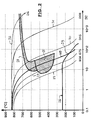
- a representation according to Figure 2 with a logarithmic scale of the abscissa has long been common in metallurgy. From the starting point (0.1 sec) from the first abscissa line it is 10 seconds to the second Abscissa 100 seconds, almost 2 minutes, and until the third Abscissa 1000 seconds, almost 17 minutes etc.
- FIG. 2 shows a so-called Z-T-U diagram (time-temperature conversion), when on the abscissa on a logarithmic scale the time in Seconds and the temperature is plotted on the ordinate on a linear scale are.
- the 100Cr6 steel is entered for the difficult-to-harden steel Pearlite area 24, the intermediate structure area 25 (bainite area) and the upper boundary line of the martensite area 26. These areas represent the material structure and properties for the steel 100Cr6 (1.2067).
- the quenching curves 27 to 32 are now entered for a rod with a 25 mm diameter and the following quenching parameters: austenitizing temperature 830 ° C. and helium as quenching gas.
- austenitizing temperature 830 ° C. and helium as quenching gas By changing the quenching speed, for example by changing the pressure, temperature and / or speed of the quenching gas, the various final hardnesses shown on the surface can now be achieved: Curve Vickers hardness HV 27 904 28 675 29 410 30 315 31 268 32 216th
- the bold curve represents the following quenching conditions:
- the final hardness increases as the curves move to the right ever lower, until the end only the normal hardness of the Material is present.
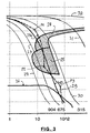
- FIG. 3 now shows an enlarged detail from Figure 2 with the following Additions in a greatly simplified and exaggerated form:
- the actual quenching curve 29a (dashed) now represents the one according to the invention Sensor unit by comparison with a stored setpoint curve according to curve 29 that the quenching rate is too slow.
- the quenching rate is now increased, and the Curve 29a undercuts curve 29.
Landscapes
- Chemical & Material Sciences (AREA)
- Engineering & Computer Science (AREA)
- Materials Engineering (AREA)
- Thermal Sciences (AREA)
- Crystallography & Structural Chemistry (AREA)
- Mechanical Engineering (AREA)
- Physics & Mathematics (AREA)
- Metallurgy (AREA)
- Organic Chemistry (AREA)
- Heat Treatment Of Articles (AREA)
- Control Of Heat Treatment Processes (AREA)
- Heat Treatments In General, Especially Conveying And Cooling (AREA)
- Sampling And Sample Adjustment (AREA)
- Investigating Or Analyzing Materials Using Thermal Means (AREA)
Abstract
Description
- die zeitlichen Abkühlverläufe mit Sollwertvorgaben verglichen werden und wenn die Differenzen zwischen den Istwerten und den Sollwertvorgaben zur Regelung mindestens einer Größe aus der Gruppe Gasdruck, Gasgeschwindigkeit und Kühlleistung eines Wärmetauschers verwendet werden,
- der Meßkörper vor dem Einbringen der Werkstücke in die mit dem Meßkörper ausgestattete Abschreckkammer auf die vorgegebene Ausgangstemperatur aufgeheizt wird und wenn nach dem Einbringen der Werkstücke in die Abschreckkammer die Beheizung des Meßkörpers abgebrochen wird,
- die Temperatur der Gasatmosphäre mittels eines zusätzlichen und vom Meßkörper unabhängigen Thermofühlers gemessen und hieraus unter Berücksichtigung der Meßwerte der Thermofühler des Meßkörpers der Wärmeübergangskoeffizient bestimmt wird,
- die Aufheizung des Meßkörpers durch eine den Meßkörper umgebende Induktionsspule und/oder eine im Meßkörper angeordnete Heizeinrichtung (z.B. eine Heizpatrone) als Heizeinrichtung durchgeführt wird, und/oder dadurch, daß der Meßkörper durch direkten Stromdurchgang aufgeheizt wird,
- der Temperaturverlauf durch einen im Oberflächenbereich des Meßkörpers angeordneten Thermofühler bestimmt wird, und/oder, wenn
- der Temperaturverlauf durch einen im Zentrum des Meßkörpers angeordneten Thermofühler bestimmt wird,
- die dem Meßkörper zugeordnete Heizeinrichtung eine den Meßkörper umgebende Induktionsspule, eine im Meßkörper angeordnete Heizeinrichtung oder der Meßkörper selbst ist, der zu diesem Zweck in der Stromkreis einer Niederspannungs-Stromquelle gelegt ist,
- zur Erfassung der Temperatur der Gasatmosphäre ein zusätzlicher und vom Meßkörper unabhängiger Thermofühler vorgesehen ist,. durch den unter Berücksichtigung der Meßwerte der Thermofühler des Meßkörpers der Wärmeübergangskoeffizient bestimmbar ist,
- die Thermofühler des Meßkörpers einer Zentraleinheit mit Speicherplätzen aufgeschaltet sind, in der die zeitlichen Verläufe der Meßwerte der Thermofühler mit vorgegebenen und gespeicherten Sollwertkurven vergleichbar sind,
- die Stromquelle der Heizeinrichtung über eine Zentraleinheit nach Erreichen der in der Zentraleinheit vorgebbaren Ausgangstemperatur des Meßkörpers abschaltbar ist,
- die Zentraleinheit über eine Steuerleitung einem Mittelfrequenzgenerator für die Versorgung der Induktionsspule aufgeschaltet ist und wenn die Induktionsspule nach Erreichen der in der Zentraleinheit vorgebbaren Ausgangstemperatur des Meßkörpers durch die Zentraleinheit abschaltbar ist,
- der Meßkörper hinsichtlich mindestens einer der Größen Werkstoff, Masse, Geometrie und Emissionsverhalten den entsprechenden Größen der Werkstücke entsprechend beschaffen ist,
- der Meßkörper als Zylinder ausgeführt ist, und/oder, wenn
- der Meßkörper (5) aus einer austenitischen Legierung mit niedrigem Emissionskoeffizienten ausgebildet ist.
- Figur 1
- einen Schnitt durch eine Sensoreinheit mit einem Meßkörper in Verbindung mit einem Blockschaltbild für die Signalerzeugung und -verarbeitung,
- Figur 2
- ein Z-T-U-Diagramm des Stahles 100Cr6 mit eingezeichneten Abkühlkurven des Meßkörpers mit verschiedenen Abschreckgeschwindigkeiten und
- Figur 3
- eine Ausschnittvergrößerung aus Figur 2 mit einer eingezeichneten Regelkurve.
| Kurve | Vickers-Härte HV |
| 27 | 904 |
| 28 | 675 |
| 29 | 410 |
| 30 | 315 |
| 31 | 268 |
| 32 | 216. |
- 1
- Kammer
- 2
- Flansch
- 3
- Isolierdurchführung
- 4
- Sensoreinheit
- 5
- Meßkörper
- 6
- Thermofühler
- 7
- Thermofühler
- 8
- Träger
- 9
- Heizeinrichtung
- 10
- Pfeil
- 11
- Pfeil
- 12
- Mittelfrequenzgenerator
- 13
- Steuerleitung
- 14
- Thermofühler
- 15
- Zentraleinheit
- 16
- Eingabetastatur
- 17
- Display
- 18
- Datenleitung
- 19
- Drucker
- 20
- Diskettenlaufwerk
- 21
- Pfeile
- 22
- Abschreckkurve
- 23
- Abschreckkurve
- 24
- Bereich
- 25
- Bereich
- 26
- Bereich
- 27
- Kurve
- 28
- Kurve
- 29
- Kurve
- 30
- Kurve
- 31
- Kurve
- 32
- Kurve
Claims (22)
- Verfahren zum Bestimmen der Abkühlwirkung einer strömenden Gasatmosphäre auf in einer Heizkammer aufgeheizte Werkstücke, insbesondere beim Härten von Werkstücken aus Stahl, durch einen auf Werkstücktemperatur erhitzten, mit mindestens einem Temperaturfühler (6, 7) versehenen Meßkörper (5), der in einer Abschreckkammer der über die Werkstücke geführten Gasströmung ausgesetzt ist, dadurch gekennzeichnet, daß der Meßkörper (5) außerhalb der Werkstücke lagefest angeordnet und mittels einer ihm unmittelbar zugeordneten Heizeinrichtung (9) auf eine vorgegebene Ausgangstemperatur aufgeheizt und anschließend zusammen mit den Werkstücken der strömenden Gasatmosphäre ausgesetzt wird und daß die hierbei am Meßkörper (5) gemessenen zeitlichen Abkühlverläufe gemessen werden.
- Verfahren nach Anspruch 1, dadurch gekennzeichnet, daß die zeitlichen Abkühlverläufe mit Sollwertvorgaben verglichen werden und daß die Differenzen zwischen den Istwerten und den Sollwertvorgaben zur Regelung mindestens einer Größe aus der Gruppe Gasdruck, Gasgeschwindigkeit und Kühlleistung eines Wärmetauschers verwendet werden.
- Verfahren nach Anspruch 1, dadurch gekennzeichnet, daß der Meßkörper (5) vor dem Einbringen der Werkstücke in die mit dem Meßkörper (5) ausgestattete Abschreckkammer auf die vorgegebene Ausgangstemperatur aufgeheizt wird und daß nach dem Einbringen der Werkstücke in die Abschreckkammer die Beheizung des Meßkörpers (5) abgebrochen wird.
- Verfahren nach Anspruch 1, dadurch gekennzeichnet, daß die Temperatur der Gasatmosphäre mittels eines zusätzlichen und vom Meßkörper (5) unabhängigen Thermofühlers (14) gemessen und hieraus unter Berücksichtigung der Meßwerte der Thermofühler (6, 7) des Meßkörpers (5) der Wärmeübergangskoeffizient bestimmt wird.
- Verfahren nach Anspruch 1, dadurch gekennzeichnet, daß die Aufheizung des Meßkörpers (5) durch eine den Meßkörper (5) umgebende Induktionsspule als Heizeinrichtung (9) durchgeführt wird.
- Verfahren nach Anspruch 1, dadurch gekennzeichnet, daß die Aufheizung des Meßkörpers (5) durch eine im Meßkörper (5) angeordnete Heizeinrichtung durchgeführt wird.
- Verfahren nach Anspruch 1, dadurch gekennzeichnet, daß der Meßkörper (5) durch Stromdurchgang aufgeheizt wird.
- Verfahren nach Anspruch 1, dadurch gekennzeichnet, daß der Temperaturverlauf durch einen im Oberflächenbereich des Meßkörpers (5) angeordneten Thermofühler (6) bestimmt wird.
- Verfahren nach Anspruch 1, dadurch gekennzeichnet, daß der Temperaturverlauf durch einen im Zentrum des Meßkörpers (5) angeordneten Thermofühler (7) bestimmt wird.
- Vorrichtung zum Bestimmen der Abkühlwirkung einer strömenden Gasatmospäre auf Werkstücke, die in einer Heizkammer aufgeheizt worden sind, insbesondere zum Härten von Werkstücken aus Stahl, durch einen auf Werkstücktemperatur aufheizbaren, mit mindestens einem Temperaturfühler (6, 7) versehenen Meßkörper (5), der in einer Abschreckkammer angeordnet ist, dadurch gekennzeichnet, daß dem außerhalb der Werkstücke lagefest angeordneten Meßkörper (5) unmittelbar eine eigene an eine Stromquelle anschließbaren Heizeinrichtung (9) zugeordnet ist, mittels welcher der Meßkörper (5) auf eine vorgebbare Ausgangstemperatur aufheizbar ist, und daß der Meßkörper (5) im Strömungsweg der über die Werkstücke führbaren Gasströmung angeordnet ist.
- Vorrichtung nach Anspruch 10, dadurch gekennzeichnet, daß die dem Meßkörper (5) zugeordnete Heizeinrichtung (9) eine den Meßkörper (5) umgebende Induktionsspule ist.
- Vorrichtung nach Anspruch 10, dadurch gekennzeichnet, daß die dem Meßkörper (5) zugeordnete Heizeinrichtung (9) eine im Meßkörper (5) angeordnete Heizeinrichtung ist.
- Vorrichtung nach Anspruch 10, dadurch gekennzeichnet, daß der Meßkörpers (5) in den Stromkreis einer Niederspannungs-Stromquelle geschaltet ist.
- Vorrichtung nach Anspruch 10, dadurch gekennzeichnet, daß zur Erfassung der Temperatur der Gasatmosphäre ein zusätzlicher und vom Meßkörper (5) unabhängiger Thermofühler (14) vorgesehen ist, durch den unter Berücksichtigung der Meßwerte der Thermofühler (6, 7) des Meßkörpers (5) der Wärmeübergangskoeffizient bestimmbar ist.
- Vorrichtung nach Anspruch 10, dadurch gekennzeichnet, daß die Thermofühler (6, 7) des Meßkörpers (5) einer Zentraleinheit (15) mit Speicherplätzen aufgeschaltet sind, in der die zeitlichen Verläufe der Meßwerte der Thermofühler (6, 7) mit vorgegebenen und gespeicherten Sollwertkurven vergleichbar sind.
- Vorrichtung nach Anspruch 10 dadurch gekennzeichnet, daß die Stromquelle der Heizeinrichtung (9) über eine Zentraleinheit (15) nach Erreichen der in der Zentraleinheit (15) vorgebbaren Ausgangstemperatur des Meßkörpers (5) abschaltbar ist.
- Vorrichtung nach Anspruch 16 dadurch gekennzeichnet, daß die Zentraleinheit (15) über eine Steuerleitung (13) einem Mittelfrequenzgenerator (12) für die Versorgung der Induktionsspule (9) aufgeschaltet ist und daß die Induktionsspule (9) nach Erreichen der in der Zentraleinheit (15) vorgebbaren Ausgangstemperatur des Meßkörpers (5) durch die Zentraleinheit (15) abschaltbar ist.
- Vorrichtung nach Anspruch 10, dadurch gekennzeichnet, daß der Meßkörper (5) hinsichtlich mindestens einer der Größen Werkstoff, Masse, Geometrie und Emissionsverhalten den entsprechenden Größen der Werkstücke entsprechend beschaffen ist.
- Vorrichtung nach Anspruch 10, dadurch gekennzeichnet, daß der Meßkörper (5) als Zylinder ausgeführt ist.
- Vorrichtung nach Anspruch 10, dadurch gekennzeichnet, daß der Meßkörper (5) aus einer austenitischen Legierung mit niedrigem Emissionskoeffizienten ausgebildet ist.
- Anwendung des Verfahrens nach Anspruch 1 für die Hochdruck--Gasabschreckung von Werkstücken in einer Abschreckkammer mit einem Wärmetauscher bei Gasdrücken zwischen 0,5 und 5,0 MPa, vorzugsweise zwischen 1,0 und 4,0 MPa.
- Anwendung der Vorrichtung nach Anspruch 10 für die Hochdruck--Gasabschreckung von Werkstücken in einer Abschreckkammer mit einem Wärmetauscher bei Gasdrücken zwischen 0,5 und 5,0 MPa, vorzugsweise zwischen 1,0 und 4,0 MPa.
Applications Claiming Priority (2)
| Application Number | Priority Date | Filing Date | Title |
|---|---|---|---|
| DE10030046 | 2000-06-19 | ||
| DE10030046A DE10030046C1 (de) | 2000-06-19 | 2000-06-19 | Verfahren und Vorrichtung zum Bestimmen der Abkühlwirkung einer strömenden Gasatmosphäre auf Werkstücke |
Publications (3)
| Publication Number | Publication Date |
|---|---|
| EP1167548A2 true EP1167548A2 (de) | 2002-01-02 |
| EP1167548A3 EP1167548A3 (de) | 2004-01-02 |
| EP1167548B1 EP1167548B1 (de) | 2005-03-16 |
Family
ID=7646193
Family Applications (1)
| Application Number | Title | Priority Date | Filing Date |
|---|---|---|---|
| EP01110912A Expired - Lifetime EP1167548B1 (de) | 2000-06-19 | 2001-05-05 | Verfahren und Vorrichtung zum Bestimmen der Abkühlwirkung einer strömenden Gasatmosphäre auf Werkstücke |
Country Status (4)
| Country | Link |
|---|---|
| US (1) | US6554922B2 (de) |
| EP (1) | EP1167548B1 (de) |
| AT (1) | ATE291102T1 (de) |
| DE (2) | DE10030046C1 (de) |
Cited By (1)
| Publication number | Priority date | Publication date | Assignee | Title |
|---|---|---|---|---|
| WO2023094557A1 (de) * | 2021-11-25 | 2023-06-01 | Ald Vacuum Technologies Gmbh | Verfahren und system zum bainitisieren metallischer werkstücke |
Families Citing this family (7)
| Publication number | Priority date | Publication date | Assignee | Title |
|---|---|---|---|---|
| CH696042A5 (fr) * | 2002-11-28 | 2006-11-30 | Ecole D Ingenieurs Du Canton D | Procédé et dispositif de mesure de la conductivité thermique d'un fluide multifonctionnel. |
| US20060102620A1 (en) * | 2004-11-12 | 2006-05-18 | Ntn Corporation | Heat treat process |
| FR2880898B1 (fr) * | 2005-01-17 | 2007-05-11 | Const Mecaniques Sa Et | Cellule de trempe au gaz pour pieces en acier |
| EP2222428B1 (de) * | 2007-12-14 | 2016-11-16 | Quintus Technologies AB | Anordnung zum isostatischen heisspressen |
| EP2131168A1 (de) * | 2008-06-04 | 2009-12-09 | Siemens Aktiengesellschaft | Verfahren und Vorrichtung zur Erkennung von Kapazitätsänderungen in einer Flüssigkeit und Turbine |
| DE102009041041B4 (de) * | 2009-09-10 | 2011-07-14 | ALD Vacuum Technologies GmbH, 63450 | Verfahren und Vorrichtung zum Härten von Werkstücken, sowie nach dem Verfahren gehärtete Werkstücke |
| CN108531692B (zh) * | 2018-07-06 | 2023-12-26 | 江苏南钢通恒特材科技有限公司 | 感应正火生产线 |
Family Cites Families (6)
| Publication number | Priority date | Publication date | Assignee | Title |
|---|---|---|---|---|
| DE3037638A1 (de) * | 1980-10-04 | 1982-05-13 | Joachim Dr.-Ing. 7251 Warmbronn Wünning | Verfahren zur bestimmung der abschreckwirkung eines abschreckmediums, insbesondere beim haerten von stahl |
| US4412752A (en) * | 1981-09-21 | 1983-11-01 | International Harvester Co. | Method and apparatus for determining the cooling characteristics of a quenching medium |
| DE3736501C1 (de) * | 1987-10-28 | 1988-06-09 | Degussa | Verfahren zur Waermebehandlung metallischer Werkstuecke |
| JP2623359B2 (ja) * | 1990-06-28 | 1997-06-25 | 高周波熱錬株式会社 | 冷却溶液の冷却能試験方法及び装置 |
| DE4135313A1 (de) * | 1991-10-25 | 1993-04-29 | Ipsen Ind Int Gmbh | Verfahren zum abkuehlen einer werkstueckcharge innerhalb eines waermebehandlungsprozesses |
| US5918473A (en) * | 1997-05-09 | 1999-07-06 | Alcan International Limited | Method and apparatus for measuring quenchant properties of coolants |
-
2000
- 2000-06-19 DE DE10030046A patent/DE10030046C1/de not_active Expired - Fee Related
-
2001
- 2001-05-05 AT AT01110912T patent/ATE291102T1/de active
- 2001-05-05 DE DE50105589T patent/DE50105589D1/de not_active Expired - Lifetime
- 2001-05-05 EP EP01110912A patent/EP1167548B1/de not_active Expired - Lifetime
- 2001-05-31 US US09/871,158 patent/US6554922B2/en not_active Expired - Lifetime
Cited By (1)
| Publication number | Priority date | Publication date | Assignee | Title |
|---|---|---|---|---|
| WO2023094557A1 (de) * | 2021-11-25 | 2023-06-01 | Ald Vacuum Technologies Gmbh | Verfahren und system zum bainitisieren metallischer werkstücke |
Also Published As
| Publication number | Publication date |
|---|---|
| DE10030046C1 (de) | 2001-09-13 |
| DE50105589D1 (de) | 2005-04-21 |
| EP1167548B1 (de) | 2005-03-16 |
| EP1167548A3 (de) | 2004-01-02 |
| US20020036075A1 (en) | 2002-03-28 |
| US6554922B2 (en) | 2003-04-29 |
| ATE291102T1 (de) | 2005-04-15 |
Similar Documents
| Publication | Publication Date | Title |
|---|---|---|
| Soliman et al. | Tensile properties and bake hardening response of dual phase steels with varied martensite volume fraction | |
| EP2753439B1 (de) | Giessverfahren, insbesondere stranggiessverfahren | |
| EP1289691B2 (de) | Verfahren zum stranggiessen eines metallstranges | |
| EP1167548B1 (de) | Verfahren und Vorrichtung zum Bestimmen der Abkühlwirkung einer strömenden Gasatmosphäre auf Werkstücke | |
| EP3132062A1 (de) | Verfahren und vorrichtung zur herstellung eines bandstahls | |
| DE102019208736A1 (de) | Verfahren zum Gießen eines Gießstrangs in einer Stranggießanlage | |
| DE102009051157B4 (de) | Kammerofen mit Übertemperatur | |
| DE3733147A1 (de) | Verfahren zum laserwaermebehandeln, wie laserhaerten, laserweichgluehen, laserrekristallisieren von bauteilen in festem zustand | |
| EP1948834B1 (de) | Verfahren und vorrichtung zur kontinuierlichen ausbildung eines bainitgefüges in einem kohlenstoffstahl, insbesondere in einem bandstahl | |
| DE4135313C2 (de) | ||
| DE10044362A1 (de) | Verfahren und Ofenanlage zum Vergüten einer Charge von Werkstücken aus Stahl | |
| Pietrzyk et al. | Simulation of the behaviour of voids in steel plates during hot rolling | |
| Park et al. | Advanced temperature control of high carbon steel for hot strip mills | |
| DE102016200077A1 (de) | Verfahren und System zum Steuern und/oder Regeln einer Erwärmung eines gegossenen oder gewalzten Metallprodukts | |
| EP3966356B1 (de) | Verfahren zur wärmebehandlung eines metallischen produkts | |
| Mallow et al. | Investigations on case hardening of an additive manufactured steel 20MnCr5 (via PBF-LB/M) | |
| Kahra et al. | Heat Transfers Coefficients of Directly and Indirectly Cooled Component Areas during Air-Water Spray Cooling | |
| Liu et al. | Effects of heating and quenching processing parameters on phase transformation of 55CrMo steel | |
| Kawulok et al. | Microstructure influenced by controlled rolling, cooling and thermal processing of seamless tubes made of steel 25CrMo4 | |
| Martschin et al. | Tailoring the hardness in multi-stage press hardening of 22MnB5 sheet material in a progressive die | |
| Barełkowski et al. | Development of a technology of isothermal annealing with the use of the forging heat for chromium-molybdenum steel | |
| DE102018105782A1 (de) | Verfahren und Behandlungsvorrichtung zur Herstellung von pulvermetallurgischen Sinterformteilen | |
| DE2454400A1 (de) | Vorrichtung zur untersuchung der haertbarkeit von gut durchhaertenden staehlen | |
| DE102023136634A1 (de) | Verfahren zum Bestimmen von Gefügeumwandlungen und/oder Gefügearten und/oder von Werkstoffkenngrößen eines Werkstoffes eines Werkstücks und Vorrichtung hierzu | |
| DE2104826C3 (de) | Vorrichtung zur Durchführung von Stirnabschreckversuchen an zylindrischen Stahlprobenkörpern |
Legal Events
| Date | Code | Title | Description |
|---|---|---|---|
| PUAI | Public reference made under article 153(3) epc to a published international application that has entered the european phase |
Free format text: ORIGINAL CODE: 0009012 |
|
| AK | Designated contracting states |
Kind code of ref document: A2 Designated state(s): AT BE CH CY DE DK ES FI FR GB GR IE IT LI LU MC NL PT SE TR |
|
| AX | Request for extension of the european patent |
Free format text: AL;LT;LV;MK;RO;SI |
|
| PUAL | Search report despatched |
Free format text: ORIGINAL CODE: 0009013 |
|
| AK | Designated contracting states |
Kind code of ref document: A3 Designated state(s): AT BE CH CY DE DK ES FI FR GB GR IE IT LI LU MC NL PT SE TR |
|
| AX | Request for extension of the european patent |
Extension state: AL LT LV MK RO SI |
|
| RIC1 | Information provided on ipc code assigned before grant |
Ipc: 7C 21D 1/613 A Ipc: 7G 01N 33/00 B Ipc: 7C 21D 1/55 B Ipc: 7C 21D 11/00 B |
|
| 17P | Request for examination filed |
Effective date: 20040213 |
|
| GRAP | Despatch of communication of intention to grant a patent |
Free format text: ORIGINAL CODE: EPIDOSNIGR1 |
|
| AKX | Designation fees paid |
Designated state(s): AT BE CH CY DE DK ES FI FR GB GR IE IT LI LU MC NL PT SE TR |
|
| GRAS | Grant fee paid |
Free format text: ORIGINAL CODE: EPIDOSNIGR3 |
|
| GRAA | (expected) grant |
Free format text: ORIGINAL CODE: 0009210 |
|
| AK | Designated contracting states |
Kind code of ref document: B1 Designated state(s): AT BE CH CY DE DK ES FI FR GB GR IE IT LI LU MC NL PT SE TR |
|
| PG25 | Lapsed in a contracting state [announced via postgrant information from national office to epo] |
Ref country code: IT Free format text: LAPSE BECAUSE OF FAILURE TO SUBMIT A TRANSLATION OF THE DESCRIPTION OR TO PAY THE FEE WITHIN THE PRESCRIBED TIME-LIMIT;WARNING: LAPSES OF ITALIAN PATENTS WITH EFFECTIVE DATE BEFORE 2007 MAY HAVE OCCURRED AT ANY TIME BEFORE 2007. THE CORRECT EFFECTIVE DATE MAY BE DIFFERENT FROM THE ONE RECORDED. Effective date: 20050316 Ref country code: IE Free format text: LAPSE BECAUSE OF FAILURE TO SUBMIT A TRANSLATION OF THE DESCRIPTION OR TO PAY THE FEE WITHIN THE PRESCRIBED TIME-LIMIT Effective date: 20050316 Ref country code: FI Free format text: LAPSE BECAUSE OF FAILURE TO SUBMIT A TRANSLATION OF THE DESCRIPTION OR TO PAY THE FEE WITHIN THE PRESCRIBED TIME-LIMIT Effective date: 20050316 Ref country code: NL Free format text: LAPSE BECAUSE OF FAILURE TO SUBMIT A TRANSLATION OF THE DESCRIPTION OR TO PAY THE FEE WITHIN THE PRESCRIBED TIME-LIMIT Effective date: 20050316 Ref country code: TR Free format text: LAPSE BECAUSE OF FAILURE TO SUBMIT A TRANSLATION OF THE DESCRIPTION OR TO PAY THE FEE WITHIN THE PRESCRIBED TIME-LIMIT Effective date: 20050316 |
|
| REG | Reference to a national code |
Ref country code: GB Ref legal event code: FG4D Free format text: NOT ENGLISH |
|
| REG | Reference to a national code |
Ref country code: CH Ref legal event code: EP |
|
| REG | Reference to a national code |
Ref country code: IE Ref legal event code: FG4D Free format text: GERMAN |
|
| REF | Corresponds to: |
Ref document number: 50105589 Country of ref document: DE Date of ref document: 20050421 Kind code of ref document: P |
|
| REG | Reference to a national code |
Ref country code: CH Ref legal event code: NV Representative=s name: PPS POLYVALENT PATENT SERVICE AG |
|
| PG25 | Lapsed in a contracting state [announced via postgrant information from national office to epo] |
Ref country code: LU Free format text: LAPSE BECAUSE OF NON-PAYMENT OF DUE FEES Effective date: 20050505 Ref country code: CY Free format text: LAPSE BECAUSE OF FAILURE TO SUBMIT A TRANSLATION OF THE DESCRIPTION OR TO PAY THE FEE WITHIN THE PRESCRIBED TIME-LIMIT Effective date: 20050505 |
|
| GBT | Gb: translation of ep patent filed (gb section 77(6)(a)/1977) |
Effective date: 20050420 |
|
| PG25 | Lapsed in a contracting state [announced via postgrant information from national office to epo] |
Ref country code: MC Free format text: LAPSE BECAUSE OF NON-PAYMENT OF DUE FEES Effective date: 20050531 Ref country code: BE Free format text: LAPSE BECAUSE OF NON-PAYMENT OF DUE FEES Effective date: 20050531 |
|
| PG25 | Lapsed in a contracting state [announced via postgrant information from national office to epo] |
Ref country code: GR Free format text: LAPSE BECAUSE OF FAILURE TO SUBMIT A TRANSLATION OF THE DESCRIPTION OR TO PAY THE FEE WITHIN THE PRESCRIBED TIME-LIMIT Effective date: 20050616 Ref country code: DK Free format text: LAPSE BECAUSE OF FAILURE TO SUBMIT A TRANSLATION OF THE DESCRIPTION OR TO PAY THE FEE WITHIN THE PRESCRIBED TIME-LIMIT Effective date: 20050616 |
|
| PG25 | Lapsed in a contracting state [announced via postgrant information from national office to epo] |
Ref country code: ES Free format text: LAPSE BECAUSE OF FAILURE TO SUBMIT A TRANSLATION OF THE DESCRIPTION OR TO PAY THE FEE WITHIN THE PRESCRIBED TIME-LIMIT Effective date: 20050627 |
|
| NLV1 | Nl: lapsed or annulled due to failure to fulfill the requirements of art. 29p and 29m of the patents act | ||
| PG25 | Lapsed in a contracting state [announced via postgrant information from national office to epo] |
Ref country code: PT Free format text: LAPSE BECAUSE OF FAILURE TO SUBMIT A TRANSLATION OF THE DESCRIPTION OR TO PAY THE FEE WITHIN THE PRESCRIBED TIME-LIMIT Effective date: 20050907 |
|
| REG | Reference to a national code |
Ref country code: IE Ref legal event code: FD4D |
|
| BERE | Be: lapsed |
Owner name: ALD VACUUM TECHNOLOGIES A.G. Effective date: 20050531 |
|
| PLBE | No opposition filed within time limit |
Free format text: ORIGINAL CODE: 0009261 |
|
| STAA | Information on the status of an ep patent application or granted ep patent |
Free format text: STATUS: NO OPPOSITION FILED WITHIN TIME LIMIT |
|
| ET | Fr: translation filed | ||
| 26N | No opposition filed |
Effective date: 20051219 |
|
| BERE | Be: lapsed |
Owner name: ALD VACUUM TECHNOLOGIES A.G. Effective date: 20050531 |
|
| PG25 | Lapsed in a contracting state [announced via postgrant information from national office to epo] |
Ref country code: SE Free format text: LAPSE BECAUSE OF FAILURE TO SUBMIT A TRANSLATION OF THE DESCRIPTION OR TO PAY THE FEE WITHIN THE PRESCRIBED TIME-LIMIT Effective date: 20050616 |
|
| REG | Reference to a national code |
Ref country code: CH Ref legal event code: PFA Owner name: ALD VACUUM TECHNOLOGIES AG Free format text: ALD VACUUM TECHNOLOGIES AG#WILHELM-ROHN-STRASSE 35#63450 HANAU (DE) -TRANSFER TO- ALD VACUUM TECHNOLOGIES AG#WILHELM-ROHN-STRASSE 35#63450 HANAU (DE) |
|
| REG | Reference to a national code |
Ref country code: FR Ref legal event code: PLFP Year of fee payment: 16 |
|
| PGFP | Annual fee paid to national office [announced via postgrant information from national office to epo] |
Ref country code: CH Payment date: 20160519 Year of fee payment: 16 Ref country code: GB Payment date: 20160520 Year of fee payment: 16 Ref country code: DE Payment date: 20160520 Year of fee payment: 16 |
|
| PGFP | Annual fee paid to national office [announced via postgrant information from national office to epo] |
Ref country code: FR Payment date: 20160520 Year of fee payment: 16 Ref country code: AT Payment date: 20160520 Year of fee payment: 16 |
|
| REG | Reference to a national code |
Ref country code: DE Ref legal event code: R119 Ref document number: 50105589 Country of ref document: DE |
|
| REG | Reference to a national code |
Ref country code: CH Ref legal event code: PL |
|
| REG | Reference to a national code |
Ref country code: AT Ref legal event code: MM01 Ref document number: 291102 Country of ref document: AT Kind code of ref document: T Effective date: 20170505 |
|
| GBPC | Gb: european patent ceased through non-payment of renewal fee |
Effective date: 20170505 |
|
| PG25 | Lapsed in a contracting state [announced via postgrant information from national office to epo] |
Ref country code: AT Free format text: LAPSE BECAUSE OF NON-PAYMENT OF DUE FEES Effective date: 20170505 |
|
| PG25 | Lapsed in a contracting state [announced via postgrant information from national office to epo] |
Ref country code: CH Free format text: LAPSE BECAUSE OF NON-PAYMENT OF DUE FEES Effective date: 20170531 Ref country code: LI Free format text: LAPSE BECAUSE OF NON-PAYMENT OF DUE FEES Effective date: 20170531 |
|
| REG | Reference to a national code |
Ref country code: FR Ref legal event code: ST Effective date: 20180131 |
|
| PG25 | Lapsed in a contracting state [announced via postgrant information from national office to epo] |
Ref country code: DE Free format text: LAPSE BECAUSE OF NON-PAYMENT OF DUE FEES Effective date: 20171201 Ref country code: GB Free format text: LAPSE BECAUSE OF NON-PAYMENT OF DUE FEES Effective date: 20170505 |
|
| PG25 | Lapsed in a contracting state [announced via postgrant information from national office to epo] |
Ref country code: FR Free format text: LAPSE BECAUSE OF NON-PAYMENT OF DUE FEES Effective date: 20170531 |