EP1168570A2 - Enroulement de bobine pour une machine à courant continu - Google Patents
Enroulement de bobine pour une machine à courant continu Download PDFInfo
- Publication number
- EP1168570A2 EP1168570A2 EP01113405A EP01113405A EP1168570A2 EP 1168570 A2 EP1168570 A2 EP 1168570A2 EP 01113405 A EP01113405 A EP 01113405A EP 01113405 A EP01113405 A EP 01113405A EP 1168570 A2 EP1168570 A2 EP 1168570A2
- Authority
- EP
- European Patent Office
- Prior art keywords
- coil winding
- winding assembly
- set forth
- electrical coil
- electrical
- Prior art date
- Legal status (The legal status is an assumption and is not a legal conclusion. Google has not performed a legal analysis and makes no representation as to the accuracy of the status listed.)
- Withdrawn
Links
Images


Classifications
-
- H—ELECTRICITY
- H02—GENERATION; CONVERSION OR DISTRIBUTION OF ELECTRIC POWER
- H02K—DYNAMO-ELECTRIC MACHINES
- H02K1/00—Details of the magnetic circuit
- H02K1/06—Details of the magnetic circuit characterised by the shape, form or construction
- H02K1/12—Stationary parts of the magnetic circuit
- H02K1/14—Stator cores with salient poles
- H02K1/146—Stator cores with salient poles consisting of a generally annular yoke with salient poles
- H02K1/148—Sectional cores
-
- H—ELECTRICITY
- H02—GENERATION; CONVERSION OR DISTRIBUTION OF ELECTRIC POWER
- H02K—DYNAMO-ELECTRIC MACHINES
- H02K3/00—Details of windings
- H02K3/46—Fastening of windings on the stator or rotor structure
- H02K3/52—Fastening salient pole windings or connections thereto
- H02K3/521—Fastening salient pole windings or connections thereto applicable to stators only
- H02K3/522—Fastening salient pole windings or connections thereto applicable to stators only for generally annular cores with salient poles
-
- H—ELECTRICITY
- H02—GENERATION; CONVERSION OR DISTRIBUTION OF ELECTRIC POWER
- H02K—DYNAMO-ELECTRIC MACHINES
- H02K7/00—Arrangements for handling mechanical energy structurally associated with dynamo-electric machines, e.g. structural association with mechanical driving motors or auxiliary dynamo-electric machines
- H02K7/006—Structural association of a motor or generator with the drive train of a motor vehicle
-
- H—ELECTRICITY
- H02—GENERATION; CONVERSION OR DISTRIBUTION OF ELECTRIC POWER
- H02K—DYNAMO-ELECTRIC MACHINES
- H02K2203/00—Specific aspects not provided for in the other groups of this subclass relating to the windings
- H02K2203/03—Machines characterised by the wiring boards, i.e. printed circuit boards or similar structures for connecting the winding terminations
-
- H—ELECTRICITY
- H02—GENERATION; CONVERSION OR DISTRIBUTION OF ELECTRIC POWER
- H02K—DYNAMO-ELECTRIC MACHINES
- H02K2203/00—Specific aspects not provided for in the other groups of this subclass relating to the windings
- H02K2203/06—Machines characterised by the wiring leads, i.e. conducting wires for connecting the winding terminations
-
- H—ELECTRICITY
- H02—GENERATION; CONVERSION OR DISTRIBUTION OF ELECTRIC POWER
- H02K—DYNAMO-ELECTRIC MACHINES
- H02K2203/00—Specific aspects not provided for in the other groups of this subclass relating to the windings
- H02K2203/12—Machines characterised by the bobbins for supporting the windings
Definitions
- This invention relates to a coil winding for a DC machine and more particularly to an improved, simplified and lower cost coil-winding assembly for such machines.
- the winding core is comprised of radially spaced inner and outer annular elements.
- the armature cores are formed as extending teeth on one or the other of these elements.
- the core is preferably formed from a plurality of laminated electromagnetic steel plates such as silicate steel or the like.
- the outer periphery of the inner element is shrunk fit into the inner periphery of the outer element so as to form a complete assembly.
- a first feature of this invention is adapted to be embodied in an electrical coil winding assembly for a rotating electrical machine.
- the winding assembly comprises a core that is formed of annular radially inner and outer elements, which form a plurality of radially extending armature cores. Electrical coils are wound around the armature cores. Circumferentially spaced and radially extending interengaging parts on the core elements maintain the axial relationship between the core elements.
- the winding assembly comprises a core that is formed by annularly radially inner and radially outer elements forming a plurality of radially extending armature cores.
- Each of a plurality of bobbins surrounds a respective one of the armature cores.
- Electrical coils are wound around each of the bobbins.
- the bobbins and respective electrical coils are detachably connected to the core element that forms the armature cores by retaining clips. At least some of the retaining clips have end portions that extend in an axial direction beyond the core elements and a wiring plate is carried by such retaining clip end portions.
- Yet another feature of the invention is also adapted to be embodied in an electrical coil winding assembly for a rotating electrical machine.
- the assembly comprises a core that is formed by annular, radially inner and radially outer elements that form a plurality of radially extending armature cores.
- Each of a plurality of bobbins around which the respective electrical coils are wound surrounds a respective one of the armature cores.
- the bobbins have portions that form a retainer for retaining the conductor ends of the respective coils against movement.
- FIG. 1 is a cross sectional view of vehicle wheel driven by an electric motor constructed in accordance with an embodiment of the invention.
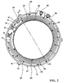
- FIG. 2 is an end elevational view showing the winding assembly of the electric motor employed in the arrangement shown in FIG. 1.
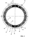
- FIG. 3 is an end elevational view of the winding assembly looking in the opposite direction from FIG. 2.
- FIG. 4 is a cross sectional view of the winding assembly taken along the line 4-4 of FIG. 2.
- FIG. 5 is an exploded view of certain of the winding assembly elements illustrating the manner and sequence of assembly.
- FIG. 6 is an enlarged perspective view showing the bobbins and the retaining structure associated therewith.
- an electric motor constructed in accordance with an embodiment of the invention is indicated generally by the reference numeral 11.
- the electric motor 11 is used in the exemplary, described embodiment for powering a vehicle wheel 12 for driving an associated vehicle (not shown) along the ground.
- the invention is described in conjunction with an electric motor, it should be readily apparent that the invention can be utilized in conjunction with other rotating electrical machines such as electrical generators.
- the specific embodiment illustrated, however, is one in which a number of the problems noted in the Background section are particularly prevalent and are solved by the construction.
- the motor 11 is contained within a motor case assembly, indicated generally by the reference numeral 13 that is affixed in a suitable manner to the aforenoted associated vehicle.
- This motor case is comprised of an inner housing element 14 and an outer housing element 15, which are secured to each other in a suitable manner and which enclose the motor 11.
- a suitable lubricant is filled into the motor case assembly 13.
- the motor 11 is comprised of a stator, which forms a winding assembly, which is indicated generally by the reference numeral 16, and a rotor, indicated generally by the reference numeral 17.
- the rotor 17 is fixed to a stub shaft 18.
- the stub shaft 18 is, in turn, journalled in the inner housing element 14 by a first anti-friction bearing 19.
- a second anti-friction bearing 21 journals the stub shaft 18 and rotor 17 on an axial shaft 22.
- the axial shaft 22 is, in turn, journalled in the outer housing element 15 by a pair of bearings 23 and 24.
- An oil seal 25 encloses the bearings and the interior of the motor case assembly 13 to prevent leakage of the lubricant contained therein.
- the wheel 12 is comprised of a rim portion 26 that mounts a suitable tire (not shown) and which is affixed to a disk portion 27.
- the disk portion 27 is, in turn, connected by fasteners 28 to a hub 29.
- the hub 29 has a splined connection to the axial shaft 22 and hence, the wheel 12 rotates with this axial shaft 22.
- a step-down planetary transmission interconnects the motor rotor 17 with the axle shaft 22 for driving it and the wheel 12.
- This step-down transmission is of the planetary type and is indicated generally by the reference numeral 31. It is comprised of a sun gear 32 that is fixed for rotation with the stub shaft 18 and is enmeshed with a plurality of planet gears 33 that are carried by a carrier 34.
- the carrier 34 is formed in part integrally with the axial shaft 22.
- These planet gears 33 are journalled on the carrier 34 by a plurality of stub shafts 35.
- the exterior periphery of these planet gears 33 are enmeshed with a ring gear 36 that is fixed relative to the motor outer housing element 15 by a carrier plate 37 that is fixed to the outer housing element 15 by threaded fasteners 38.
- the wheel 12 also forms an integral drum brake assembly.
- the hub 29 is formed with a drum brake inner surface 39 which is formed integrally with it and which is engaged by brake shoes 41 carried by actuator elements 42.
- actuator elements 42 are operated by a suitable brake actuator for bringing the brake shoes 41 into engagement with the drum brake inner surface 39 for halting the rotation of the wheel 12.
- the invention deals primarily with the construction of the electric motor 11 and particularly the stator or armature winding assembly 16 thereof which forms a plurality of armature cores.
- These armature cores are formed from laminated plates comprised of an outer member 43 and an inner member 44 which are secured together in a manner to be described.
- the inner member 44 forms a plurality of poles around which coil windings 45 are formed in a manner, which will be described in more detail shortly by reference to FIGS. 2 through 6.
- These coil windings 45 cooperate with permanent magnets 46 that are affixed to the periphery of the motor rotor 17 via a laminated electromagnetic steel plate annular magnetic bushing 50.
- the rotor 17 is primarily formed from aluminum or an aluminum alloy.
- These permanent magnets 46 are arranged so as to have alternate poles alternating in a circumferential direction around the rotor 17 of the motor 11 and in a preferred embodiment there are 12 permanent magnets 46.
- the permanent magnets 46 are formed from a material with a large magnetic flux density, such as neodymium-iron-boron.
- the armature winding assembly16 is comprised of a pair of ring-like elements comprised of an outer element, indicated generally by the reference numeral 47 and an inner element, indicated generally by the reference numeral 48. Both of these elements 47 and 48 are formed from a plurality of laminated sheets of material having high magnetic properties such as electromagnetic steel plates.
- the inner element 48 has a hub portion 49, which forms a continuous ring from which pole teeth 51 extend radially outwardly. In a preferred embodiment there are 18 of these pole teeth 51.
- the outer diameter of the pole teeth 51 is preferably slightly greater than the inner diameter 52 of the outer element 47 so as to permit shrink fit attachment there between.
- the outer element 47 has a plurality of lugs 53 formed thereon, each of which has an opening 54 so as to pass a threaded fastener 55 (FIG. 1) for fixation against rotation to the motor housing inner housing element 14.
- Bobbins are provided for embracing the teeth 51 and around which individual coil windings 45 are formed, in a manner to be described.
- the bobbins 56 are formed from a suitable insulating material such as a resin or the like and they comprise generally rectangular shaped tubular sections 57 which embrace the individual teeth 51 and inner and outer flanges 58 and 59.
- the inner flange 58 is engaged with the hub portion 49 of the inner element 48 while the outer flange 59 is spaced outwardly at the outer peripheral edge of the teeth 51.
- the inner periphery of the rectangular section 57 is formed with a plurality of resilient locking teeth 61 which will snugly engage the outer periphery of the pole teeth 51 to provide good attachment thereto.
- a key or tooth 62 is formed at one axial end of the bobbin 56 and which is designed so as to extend radially outwardly beyond the outer periphery of the pole teeth 51 and into proximity with the outer element 47 so as to engage one side thereof as clearly shown in FIG. 4 and to provide axial alignment between the inner and outer elements 47 and 48.
- certain of the bobbins 56 are formed with a recess 63, which receives one leg 64 of a L-shaped retainer key 65.
- This retainer key 65 has barb like edges 66 so that when pressed into the recess 63 the retainer key 65 will be permanently retained in the bobbin 56.
- seven (7) of the bobbins 56 receive such retainer keys 65 for a reason that will become apparent shortly.
- the leg 64 extends radially outwardly beyond the outer periphery of the pole teeth 51 as seen at 67 in FIG. 4 and engages the side of the outer element 47 opposite that engaged by the keys or teeth 62.
- the remaining leg of the retainer key 65 is provided with elongated projections 68 for a reason, which will be described shortly. It will be seen that the elongated projections 68 extends in an axial direction radially beyond the coil windings 45 and to pass through a like number of slotted openings 69 formed in a wiring board 71.
- the wiring board 71 may be affixed rigidly to complete the assembly by applying solder to the projecting ends of the elongated projections 68.
- step 1 the inner element 48 is positioned and the wound bobbins 56 are slid onto the teeth 51.
- the outer element is slipped over it and shrunk fit. This may be done by either cooling the inner element 48, heating the other outer element 47 or both and permitting these components to return to their temperature.
- the retainer key 65 are inserted to complete the axial locking at the step 3.
- the wiring board is inserted and attached by the aforenoted-soldering step.
- wiring board 71 and its relation to the coil windings 45 will now be described by primary reference to FIGS. 2 through 4 and 6, except as will be hereinafter noted.
- the side of the bobbin flange 59 opposite that that receives the retainer key 65 is formed with a slotted opening 72 across which a resilient tab 73 extends.
- the winding end, indicated at 74 may be looped under this tab 73 by lifting its outer edge 75.
- the coil windings 45 will be retained tightly in place relative to the bobbin 56 both during assembly and after assembly. This avoids the likelihood that the windings can be loosened in use.
- winding ends 74 are then connected to the wiring board 71 in a manner, which will be described by primary reference to FIGS. 2 through 4.
- the coil windings 45 are connected to each other for use in a three-phase circuit having phases identified as “U”, “V” and “W”, each having a phase difference of 120°.
- the wiring board 71 there are attached three metal conductors 76, 77 and 78, each of which is associated with the respective phases “U”, “V” and “W”.
- One end of each of these strips is provided with a respective terminal end 79, 81 and 82, respectively which have grooves for attachment to an external conductor which includes a terminal box 83 (FIG. 1) mounted in the motor case assembly 13 and specifically its inner housing element 14 and which is connected to an internal wiring harness that goes to these individual conductors 76, 77 and 78.
- the insulating plate of the wiring board 71 is formed with peripheral notches 84 over which the ends of the respective wires may be passed from the individual coil ends 74. As seen in FIG. 2 by the dotted lines, this shows how the individual coil windings may be connected to the respective terminal boards through conductors which may be formed either integrally with or separately attached to the insulating base.
- FIG. 6 Three coils are grouped with each set as may be seen by the dotted line views in FIG. 2 which are done for clarity so as to show how this connection is made.
- the remaining ends of the coil windings 45 are grouped and passed through openings in the insulating plate and which are sealed by a sealant 85 as seen in FIG. 3.
- the retaining structure shown in FIG. 6 facilitates the completion of this wiring upon assembly.
- Driving torque may be controlled by pulse controlling the "U", "V” and "W" phase currents.
- the wiring board 71 is also provided with a pair of terminals 88 and 89 (FIGS. 2 and 3), which may also be connected through the wiring harness to the terminal box 83. These may be provided for temperature sensors (not shown) that detect the temperature of the stator armature assembly.
- An improved armature winding arrangement for a rotating electrical machine such as a specifically illustrated DC motor for driving a vehicle wheel.
- the assembly is such that the armature core can be formed from two laminated pieces that are rigidly connected to each other and held against axial movement. This eliminates the need for bonding adhesive.
- an improved bobbin arrangement is employed for both permitting attachment of a wiring plate directly to the core but also for retaining the ends of the individual windings to prevent them from becoming loose either during assembly or in operation.
Landscapes
- Engineering & Computer Science (AREA)
- Power Engineering (AREA)
- Insulation, Fastening Of Motor, Generator Windings (AREA)
Applications Claiming Priority (4)
| Application Number | Priority Date | Filing Date | Title |
|---|---|---|---|
| JP2000165735 | 2000-06-02 | ||
| JP2000165735 | 2000-06-02 | ||
| US09/681,711 US6566779B2 (en) | 2000-06-02 | 2001-05-24 | Coil winding for DC machine |
| US681711 | 2001-05-24 |
Publications (2)
| Publication Number | Publication Date |
|---|---|
| EP1168570A2 true EP1168570A2 (fr) | 2002-01-02 |
| EP1168570A3 EP1168570A3 (fr) | 2004-03-17 |
Family
ID=26593211
Family Applications (1)
| Application Number | Title | Priority Date | Filing Date |
|---|---|---|---|
| EP01113405A Withdrawn EP1168570A3 (fr) | 2000-06-02 | 2001-06-01 | Enroulement de bobine pour une machine à courant continu |
Country Status (3)
| Country | Link |
|---|---|
| EP (1) | EP1168570A3 (fr) |
| CN (1) | CN1211899C (fr) |
| TW (1) | TW517430B (fr) |
Cited By (9)
| Publication number | Priority date | Publication date | Assignee | Title |
|---|---|---|---|---|
| EP1372242A3 (fr) * | 2002-05-14 | 2005-11-09 | AXIS S.p.A. | Méthode et appareil pour le bobinage de composants de machines dynamo-électriques |
| WO2009021597A2 (fr) | 2007-08-16 | 2009-02-19 | Dorma Gmbh + Co. Kg | Corps de bobine pour un stator de moteur linéaire pour une porte automatique |
| WO2010136206A3 (fr) * | 2009-05-29 | 2011-08-18 | Brose Fahrzeugteile Gmbh & Co. Kg, Würzburg | Stator pour moteur électrique |
| FR2995739A1 (fr) * | 2012-09-17 | 2014-03-21 | Valeo Equip Electr Moteur | Isolant de bobine apte a recevoir un capteur de temperature, interconnecteur pour stator et support pour capteur de temperature correspondants |
| EP2400638A3 (fr) * | 2010-06-25 | 2015-11-11 | Aumann GMBH | Procédé et dispositif de bobinage pour rembourrages destinés à des stators de moteurs à rotor intérieur |
| FR3058280A1 (fr) * | 2016-11-03 | 2018-05-04 | Valeo Equipements Electriques Moteur | Stator de machine electrique tournante muni d'un interconnecteur a configuration amelioree |
| CN111725903A (zh) * | 2019-03-22 | 2020-09-29 | 日本电产株式会社 | 定子、马达、定子的制造方法以及马达的制造方法 |
| US11245309B2 (en) * | 2013-04-03 | 2022-02-08 | Koch Engineered Solutions, Llc | Liquid cooled stator for high efficiency machine |
| GB2604034A (en) * | 2021-02-19 | 2022-08-24 | Electrified Automation Ltd | Electric machine, rotor and stator |
Families Citing this family (3)
| Publication number | Priority date | Publication date | Assignee | Title |
|---|---|---|---|---|
| JP4873264B2 (ja) * | 2008-05-30 | 2012-02-08 | アイシン・エィ・ダブリュ株式会社 | 駆動装置 |
| DE102009057446B4 (de) * | 2009-12-08 | 2013-11-14 | L-3 Communications Magnet-Motor Gmbh | Elektrische Maschine |
| CN106655569A (zh) * | 2016-10-27 | 2017-05-10 | 东莞市翰硕塑胶有限公司 | 一种家用风扇的dc三相无刷电机 |
Family Cites Families (6)
| Publication number | Priority date | Publication date | Assignee | Title |
|---|---|---|---|---|
| JPH0191628A (ja) * | 1987-10-02 | 1989-04-11 | Matsushita Electric Ind Co Ltd | 固定子 |
| JPH06169556A (ja) * | 1992-11-30 | 1994-06-14 | Matsushita Electric Ind Co Ltd | 電動機の固定子製造方法およびその固定子鉄心 |
| FR2711456B1 (fr) * | 1993-10-19 | 1995-11-24 | Valeo Systemes Dessuyage | Machine électrique tournante et son procédé de fabrication. |
| JP3248830B2 (ja) * | 1995-06-30 | 2002-01-21 | 本田技研工業株式会社 | 電動ホイールモータ |
| DE19652795A1 (de) * | 1996-12-18 | 1998-06-25 | Siemens Ag | Stator für elektrodynamische Maschinen und Verfahren zu deren Herstellung |
| JP2000032690A (ja) * | 1998-07-08 | 2000-01-28 | Sanyo Denki Co Ltd | 回転電機用固定子鉄心及び回転電機用固定子の製造方法並びに磁石回転子型電動機 |
-
2001
- 2001-05-30 TW TW90113037A patent/TW517430B/zh not_active IP Right Cessation
- 2001-06-01 EP EP01113405A patent/EP1168570A3/fr not_active Withdrawn
- 2001-06-04 CN CN 01121167 patent/CN1211899C/zh not_active Expired - Fee Related
Cited By (21)
| Publication number | Priority date | Publication date | Assignee | Title |
|---|---|---|---|---|
| EP1372242A3 (fr) * | 2002-05-14 | 2005-11-09 | AXIS S.p.A. | Méthode et appareil pour le bobinage de composants de machines dynamo-électriques |
| US7367106B2 (en) | 2002-05-14 | 2008-05-06 | Axis Usa, Inc. | Method of assembling a dynamo-electric machine component |
| US7774924B2 (en) | 2002-05-14 | 2010-08-17 | ATOP, S.p.A. | Method of winding a dynamo-electric machine component |
| US7975370B2 (en) | 2002-05-14 | 2011-07-12 | Atop S.P.A. | Apparatus for assembling dynamo-electric machine component in order to clearly describe the invention to which the claims are directed |
| WO2009021597A2 (fr) | 2007-08-16 | 2009-02-19 | Dorma Gmbh + Co. Kg | Corps de bobine pour un stator de moteur linéaire pour une porte automatique |
| WO2009021597A3 (fr) * | 2007-08-16 | 2009-04-16 | Dorma Gmbh & Co Kg | Corps de bobine pour un stator de moteur linéaire pour une porte automatique |
| CN102484400B (zh) * | 2009-05-29 | 2015-07-29 | 博泽沃尔兹堡汽车零部件有限公司 | 用于电动机的定子、电动机以及用于制造用于电动机的定子的方法 |
| WO2010136206A3 (fr) * | 2009-05-29 | 2011-08-18 | Brose Fahrzeugteile Gmbh & Co. Kg, Würzburg | Stator pour moteur électrique |
| US9413202B2 (en) | 2009-05-29 | 2016-08-09 | Brose Fahrzeugteile Gmbh & Co. Kg, Wuerzburg | Stator for an electric motor |
| CN102484400A (zh) * | 2009-05-29 | 2012-05-30 | 博泽沃尔兹堡汽车零部件有限公司 | 用于电动机的定子 |
| EP2400638A3 (fr) * | 2010-06-25 | 2015-11-11 | Aumann GMBH | Procédé et dispositif de bobinage pour rembourrages destinés à des stators de moteurs à rotor intérieur |
| FR2995739A1 (fr) * | 2012-09-17 | 2014-03-21 | Valeo Equip Electr Moteur | Isolant de bobine apte a recevoir un capteur de temperature, interconnecteur pour stator et support pour capteur de temperature correspondants |
| WO2014041265A3 (fr) * | 2012-09-17 | 2014-11-13 | Valeo Equipements Electriques Moteur | Isolant de bobine apte a recevoir un capteur de temperature, interconnecteur pour stator et support pour capteur de temperature correspondants |
| US11245309B2 (en) * | 2013-04-03 | 2022-02-08 | Koch Engineered Solutions, Llc | Liquid cooled stator for high efficiency machine |
| FR3058280A1 (fr) * | 2016-11-03 | 2018-05-04 | Valeo Equipements Electriques Moteur | Stator de machine electrique tournante muni d'un interconnecteur a configuration amelioree |
| CN109891716A (zh) * | 2016-11-03 | 2019-06-14 | 法雷奥电机设备公司 | 设置有具有改良配置的互连的旋转电机的定子 |
| WO2018083404A1 (fr) * | 2016-11-03 | 2018-05-11 | Valeo Equipements Electriques Moteur | Stator de machine electrique tournante muni d'un interconnecteur a configuration amelioree |
| CN109891716B (zh) * | 2016-11-03 | 2022-04-29 | 法雷奥电机设备公司 | 设置有具有改良配置的互连的旋转电机的定子 |
| CN111725903A (zh) * | 2019-03-22 | 2020-09-29 | 日本电产株式会社 | 定子、马达、定子的制造方法以及马达的制造方法 |
| GB2604034A (en) * | 2021-02-19 | 2022-08-24 | Electrified Automation Ltd | Electric machine, rotor and stator |
| GB2604034B (en) * | 2021-02-19 | 2023-05-31 | Electrified Automation Ltd | Electric machine, stator and insulator |
Also Published As
| Publication number | Publication date |
|---|---|
| CN1332509A (zh) | 2002-01-23 |
| EP1168570A3 (fr) | 2004-03-17 |
| CN1211899C (zh) | 2005-07-20 |
| TW517430B (en) | 2003-01-11 |
Similar Documents
| Publication | Publication Date | Title |
|---|---|---|
| US6566779B2 (en) | Coil winding for DC machine | |
| US6153957A (en) | DC brushless machine | |
| EP2329583B1 (fr) | Agencement d'isolation d'enroulement pour machines à flux axial | |
| US6873082B2 (en) | Stator assembly including a core slot insert member | |
| US6683397B2 (en) | Electric machine having at least one magnetic field detector | |
| EP1003268A1 (fr) | Machine électrique rotative | |
| EP1384306B1 (fr) | Machine electrique torique et support d'enroulement annulaire pour cette machine | |
| EP0543670B1 (fr) | Moteur électrique miniature | |
| US6313557B1 (en) | Electric motor of the electronic commutation type for applications with a feeder line | |
| JP2009118615A (ja) | ブラシレスモータ | |
| EP1168570A2 (fr) | Enroulement de bobine pour une machine à courant continu | |
| CN101192767B (zh) | 电机 | |
| US8205321B2 (en) | Method of assembling a magneto generator | |
| JP2013062901A (ja) | ステータおよびこのステータを備える回転電機 | |
| CN108631473B (zh) | 电动机 | |
| JP2002526012A (ja) | 固定子結合用尖端 | |
| JPH0588169U (ja) | 小型モータ | |
| US20040017128A1 (en) | Alternator field coil wire routing design | |
| US5268604A (en) | Armature of a small motor employing an insulating holder having a plurality of sections | |
| EP0491929B1 (fr) | Moteur electrique | |
| JPH059146U (ja) | 回転電機用固定子 | |
| US20050029892A1 (en) | Coil terminal circuit structure for rotary electrical device | |
| EP1075072B1 (fr) | Stator pour un moteur sans balais | |
| JPH11215745A (ja) | 電動モータ及びステータコアの形成方法 | |
| EP1292003A1 (fr) | Isolant pour induit d'une machine dynamo-électrique |
Legal Events
| Date | Code | Title | Description |
|---|---|---|---|
| PUAI | Public reference made under article 153(3) epc to a published international application that has entered the european phase |
Free format text: ORIGINAL CODE: 0009012 |
|
| AK | Designated contracting states |
Kind code of ref document: A2 Designated state(s): AT BE CH CY DE DK ES FI FR GB GR IE IT LI LU MC NL PT SE TR |
|
| AX | Request for extension of the european patent |
Free format text: AL;LT;LV;MK;RO;SI |
|
| PUAL | Search report despatched |
Free format text: ORIGINAL CODE: 0009013 |
|
| AK | Designated contracting states |
Kind code of ref document: A3 Designated state(s): AT BE CH CY DE DK ES FI FR GB GR IE IT LI LU MC NL PT SE TR |
|
| AX | Request for extension of the european patent |
Extension state: AL LT LV MK RO SI |
|
| 17P | Request for examination filed |
Effective date: 20040804 |
|
| AKX | Designation fees paid |
Designated state(s): DE FR GB IT |
|
| STAA | Information on the status of an ep patent application or granted ep patent |
Free format text: STATUS: THE APPLICATION HAS BEEN WITHDRAWN |
|
| 18W | Application withdrawn |
Effective date: 20051230 |