EP1169972A1 - Ablationskartierungskatheter - Google Patents
Ablationskartierungskatheter Download PDFInfo
- Publication number
- EP1169972A1 EP1169972A1 EP01305844A EP01305844A EP1169972A1 EP 1169972 A1 EP1169972 A1 EP 1169972A1 EP 01305844 A EP01305844 A EP 01305844A EP 01305844 A EP01305844 A EP 01305844A EP 1169972 A1 EP1169972 A1 EP 1169972A1
- Authority
- EP
- European Patent Office
- Prior art keywords
- electrode
- catheter
- region
- tip
- tip electrode
- Prior art date
- Legal status (The legal status is an assumption and is not a legal conclusion. Google has not performed a legal analysis and makes no representation as to the accuracy of the status listed.)
- Granted
Links
- 238000002679 ablation Methods 0.000 title abstract description 24
- 238000013507 mapping Methods 0.000 title abstract description 23
- 229920002635 polyurethane Polymers 0.000 claims description 15
- 239000004814 polyurethane Substances 0.000 claims description 15
- 239000004642 Polyimide Substances 0.000 claims description 7
- 229920001721 polyimide Polymers 0.000 claims description 7
- 229920000052 poly(p-xylylene) Polymers 0.000 claims description 4
- 239000004593 Epoxy Substances 0.000 claims description 3
- 229920000728 polyester Polymers 0.000 claims description 3
- OKTJSMMVPCPJKN-UHFFFAOYSA-N Carbon Chemical compound [C] OKTJSMMVPCPJKN-UHFFFAOYSA-N 0.000 claims description 2
- 229910052799 carbon Inorganic materials 0.000 claims description 2
- 239000000919 ceramic Substances 0.000 claims description 2
- 229910003460 diamond Inorganic materials 0.000 claims description 2
- 239000010432 diamond Substances 0.000 claims description 2
- 230000003902 lesion Effects 0.000 abstract description 11
- 210000001519 tissue Anatomy 0.000 description 25
- 239000003292 glue Substances 0.000 description 22
- 210000002216 heart Anatomy 0.000 description 17
- WABPQHHGFIMREM-UHFFFAOYSA-N lead(0) Chemical compound [Pb] WABPQHHGFIMREM-UHFFFAOYSA-N 0.000 description 17
- 238000000034 method Methods 0.000 description 15
- 230000006835 compression Effects 0.000 description 14
- 238000007906 compression Methods 0.000 description 14
- 208000007536 Thrombosis Diseases 0.000 description 12
- 210000005003 heart tissue Anatomy 0.000 description 11
- 230000000694 effects Effects 0.000 description 10
- 210000004369 blood Anatomy 0.000 description 9
- 239000008280 blood Substances 0.000 description 9
- 238000001816 cooling Methods 0.000 description 9
- 206010003119 arrhythmia Diseases 0.000 description 8
- BASFCYQUMIYNBI-UHFFFAOYSA-N platinum Chemical compound [Pt] BASFCYQUMIYNBI-UHFFFAOYSA-N 0.000 description 8
- 230000006793 arrhythmia Effects 0.000 description 7
- 230000015572 biosynthetic process Effects 0.000 description 7
- 239000011248 coating agent Substances 0.000 description 7
- 238000000576 coating method Methods 0.000 description 7
- 239000010935 stainless steel Substances 0.000 description 7
- 229910001220 stainless steel Inorganic materials 0.000 description 7
- 239000000463 material Substances 0.000 description 6
- 238000013461 design Methods 0.000 description 5
- 238000010438 heat treatment Methods 0.000 description 5
- 229920003023 plastic Polymers 0.000 description 5
- 239000004033 plastic Substances 0.000 description 5
- 238000010276 construction Methods 0.000 description 4
- 229910052697 platinum Inorganic materials 0.000 description 4
- 230000001681 protective effect Effects 0.000 description 4
- RYGMFSIKBFXOCR-UHFFFAOYSA-N Copper Chemical group [Cu] RYGMFSIKBFXOCR-UHFFFAOYSA-N 0.000 description 3
- 229920006362 Teflon® Polymers 0.000 description 3
- 230000001594 aberrant effect Effects 0.000 description 3
- 238000005476 soldering Methods 0.000 description 3
- 229910000831 Steel Inorganic materials 0.000 description 2
- 238000004873 anchoring Methods 0.000 description 2
- 210000001367 artery Anatomy 0.000 description 2
- 239000004020 conductor Substances 0.000 description 2
- 238000007796 conventional method Methods 0.000 description 2
- 230000008021 deposition Effects 0.000 description 2
- 238000006073 displacement reaction Methods 0.000 description 2
- 238000001035 drying Methods 0.000 description 2
- 210000001174 endocardium Anatomy 0.000 description 2
- PCHJSUWPFVWCPO-UHFFFAOYSA-N gold Chemical compound [Au] PCHJSUWPFVWCPO-UHFFFAOYSA-N 0.000 description 2
- 229910052737 gold Inorganic materials 0.000 description 2
- 239000010931 gold Substances 0.000 description 2
- -1 i.e. Polymers 0.000 description 2
- 229910052741 iridium Inorganic materials 0.000 description 2
- GKOZUEZYRPOHIO-UHFFFAOYSA-N iridium atom Chemical compound [Ir] GKOZUEZYRPOHIO-UHFFFAOYSA-N 0.000 description 2
- 230000007246 mechanism Effects 0.000 description 2
- 229910052751 metal Inorganic materials 0.000 description 2
- 239000002184 metal Substances 0.000 description 2
- 238000012544 monitoring process Methods 0.000 description 2
- HWLDNSXPUQTBOD-UHFFFAOYSA-N platinum-iridium alloy Chemical compound [Ir].[Pt] HWLDNSXPUQTBOD-UHFFFAOYSA-N 0.000 description 2
- 239000010959 steel Substances 0.000 description 2
- 210000003462 vein Anatomy 0.000 description 2
- 102000004506 Blood Proteins Human genes 0.000 description 1
- 108010017384 Blood Proteins Proteins 0.000 description 1
- 229910001006 Constantan Inorganic materials 0.000 description 1
- 229920001651 Cyanoacrylate Polymers 0.000 description 1
- 239000004677 Nylon Substances 0.000 description 1
- 229910000566 Platinum-iridium alloy Inorganic materials 0.000 description 1
- 239000004952 Polyamide Substances 0.000 description 1
- 229920002614 Polyether block amide Polymers 0.000 description 1
- 239000004830 Super Glue Substances 0.000 description 1
- 239000000853 adhesive Substances 0.000 description 1
- 238000004026 adhesive bonding Methods 0.000 description 1
- 230000001070 adhesive effect Effects 0.000 description 1
- 230000004075 alteration Effects 0.000 description 1
- 238000005452 bending Methods 0.000 description 1
- 239000012620 biological material Substances 0.000 description 1
- 210000005242 cardiac chamber Anatomy 0.000 description 1
- 230000001413 cellular effect Effects 0.000 description 1
- 230000015271 coagulation Effects 0.000 description 1
- 238000005345 coagulation Methods 0.000 description 1
- 230000008602 contraction Effects 0.000 description 1
- 229910052802 copper Inorganic materials 0.000 description 1
- 239000010949 copper Substances 0.000 description 1
- 238000005520 cutting process Methods 0.000 description 1
- 230000006378 damage Effects 0.000 description 1
- 230000001419 dependent effect Effects 0.000 description 1
- 238000001514 detection method Methods 0.000 description 1
- 238000003745 diagnosis Methods 0.000 description 1
- 238000009826 distribution Methods 0.000 description 1
- 238000002001 electrophysiology Methods 0.000 description 1
- 230000007831 electrophysiology Effects 0.000 description 1
- 238000005516 engineering process Methods 0.000 description 1
- 230000002708 enhancing effect Effects 0.000 description 1
- 210000001105 femoral artery Anatomy 0.000 description 1
- 238000002594 fluoroscopy Methods 0.000 description 1
- 238000002847 impedance measurement Methods 0.000 description 1
- 230000000977 initiatory effect Effects 0.000 description 1
- 230000002452 interceptive effect Effects 0.000 description 1
- 238000005259 measurement Methods 0.000 description 1
- 210000004165 myocardium Anatomy 0.000 description 1
- 229910001000 nickel titanium Inorganic materials 0.000 description 1
- HLXZNVUGXRDIFK-UHFFFAOYSA-N nickel titanium Chemical compound [Ti].[Ti].[Ti].[Ti].[Ti].[Ti].[Ti].[Ti].[Ti].[Ti].[Ti].[Ni].[Ni].[Ni].[Ni].[Ni].[Ni].[Ni].[Ni].[Ni].[Ni].[Ni].[Ni].[Ni].[Ni] HLXZNVUGXRDIFK-UHFFFAOYSA-N 0.000 description 1
- 231100000252 nontoxic Toxicity 0.000 description 1
- 230000003000 nontoxic effect Effects 0.000 description 1
- 229920001778 nylon Polymers 0.000 description 1
- 230000037361 pathway Effects 0.000 description 1
- 229920002647 polyamide Polymers 0.000 description 1
- 230000008569 process Effects 0.000 description 1
- 238000012545 processing Methods 0.000 description 1
- 230000033764 rhythmic process Effects 0.000 description 1
- 230000019491 signal transduction Effects 0.000 description 1
- 239000007787 solid Substances 0.000 description 1
- 238000002560 therapeutic procedure Methods 0.000 description 1
- 238000003466 welding Methods 0.000 description 1
Images



Classifications
-
- A—HUMAN NECESSITIES
- A61—MEDICAL OR VETERINARY SCIENCE; HYGIENE
- A61B—DIAGNOSIS; SURGERY; IDENTIFICATION
- A61B18/00—Surgical instruments, devices or methods for transferring non-mechanical forms of energy to or from the body
- A61B18/04—Surgical instruments, devices or methods for transferring non-mechanical forms of energy to or from the body by heating
- A61B18/12—Surgical instruments, devices or methods for transferring non-mechanical forms of energy to or from the body by heating by passing a current through the tissue to be heated, e.g. high-frequency current
- A61B18/14—Probes or electrodes therefor
- A61B18/1492—Probes or electrodes therefor having a flexible, catheter-like structure, e.g. for heart ablation
-
- A—HUMAN NECESSITIES
- A61—MEDICAL OR VETERINARY SCIENCE; HYGIENE
- A61B—DIAGNOSIS; SURGERY; IDENTIFICATION
- A61B17/00—Surgical instruments, devices or methods
- A61B17/00234—Surgical instruments, devices or methods for minimally invasive surgery
- A61B2017/00292—Surgical instruments, devices or methods for minimally invasive surgery mounted on or guided by flexible, e.g. catheter-like, means
- A61B2017/003—Steerable
-
- A—HUMAN NECESSITIES
- A61—MEDICAL OR VETERINARY SCIENCE; HYGIENE
- A61B—DIAGNOSIS; SURGERY; IDENTIFICATION
- A61B18/00—Surgical instruments, devices or methods for transferring non-mechanical forms of energy to or from the body
- A61B2018/00053—Mechanical features of the instrument of device
- A61B2018/00059—Material properties
- A61B2018/00071—Electrical conductivity
- A61B2018/00083—Electrical conductivity low, i.e. electrically insulating
-
- A—HUMAN NECESSITIES
- A61—MEDICAL OR VETERINARY SCIENCE; HYGIENE
- A61B—DIAGNOSIS; SURGERY; IDENTIFICATION
- A61B18/00—Surgical instruments, devices or methods for transferring non-mechanical forms of energy to or from the body
- A61B2018/00053—Mechanical features of the instrument of device
- A61B2018/00059—Material properties
- A61B2018/00089—Thermal conductivity
- A61B2018/00095—Thermal conductivity high, i.e. heat conducting
-
- A—HUMAN NECESSITIES
- A61—MEDICAL OR VETERINARY SCIENCE; HYGIENE
- A61B—DIAGNOSIS; SURGERY; IDENTIFICATION
- A61B18/00—Surgical instruments, devices or methods for transferring non-mechanical forms of energy to or from the body
- A61B2018/00315—Surgical instruments, devices or methods for transferring non-mechanical forms of energy to or from the body for treatment of particular body parts
- A61B2018/00345—Vascular system
- A61B2018/00351—Heart
-
- A—HUMAN NECESSITIES
- A61—MEDICAL OR VETERINARY SCIENCE; HYGIENE
- A61B—DIAGNOSIS; SURGERY; IDENTIFICATION
- A61B18/00—Surgical instruments, devices or methods for transferring non-mechanical forms of energy to or from the body
- A61B2018/00571—Surgical instruments, devices or methods for transferring non-mechanical forms of energy to or from the body for achieving a particular surgical effect
- A61B2018/00577—Ablation
-
- A—HUMAN NECESSITIES
- A61—MEDICAL OR VETERINARY SCIENCE; HYGIENE
- A61B—DIAGNOSIS; SURGERY; IDENTIFICATION
- A61B18/00—Surgical instruments, devices or methods for transferring non-mechanical forms of energy to or from the body
- A61B2018/00636—Sensing and controlling the application of energy
- A61B2018/00773—Sensed parameters
- A61B2018/00839—Bioelectrical parameters, e.g. ECG, EEG
-
- A—HUMAN NECESSITIES
- A61—MEDICAL OR VETERINARY SCIENCE; HYGIENE
- A61B—DIAGNOSIS; SURGERY; IDENTIFICATION
- A61B18/00—Surgical instruments, devices or methods for transferring non-mechanical forms of energy to or from the body
- A61B18/04—Surgical instruments, devices or methods for transferring non-mechanical forms of energy to or from the body by heating
- A61B18/12—Surgical instruments, devices or methods for transferring non-mechanical forms of energy to or from the body by heating by passing a current through the tissue to be heated, e.g. high-frequency current
- A61B18/1206—Generators therefor
- A61B2018/1246—Generators therefor characterised by the output polarity
- A61B2018/126—Generators therefor characterised by the output polarity bipolar
-
- A—HUMAN NECESSITIES
- A61—MEDICAL OR VETERINARY SCIENCE; HYGIENE
- A61B—DIAGNOSIS; SURGERY; IDENTIFICATION
- A61B34/00—Computer-aided surgery; Manipulators or robots specially adapted for use in surgery
- A61B34/20—Surgical navigation systems; Devices for tracking or guiding surgical instruments, e.g. for frameless stereotaxis
- A61B2034/2046—Tracking techniques
- A61B2034/2051—Electromagnetic tracking systems
Definitions
- the present invention is directed to a catheter for electric diagnosis and treatment of the heart, and more particularly to a catheter for mapping and ablation.
- Electrode catheters have been in common use in medical practice for many years. They are used to stimulate and map electrical activity in the heart and to ablate sites of aberrant electrical activity.
- the electrode catheter is inserted into a major vein or artery, e.g., femoral artery, and then guided into the chamber of the heart which is of concern. Once the catheter is positioned within the heart, the location of aberrant electrical activity within the heart is then located.
- a major vein or artery e.g., femoral artery
- One location technique involves an electrophysiological mapping procedure whereby the electrical signals emanating from the conductive endocardial tissues are systematically monitored and a map is created of those signals. By analyzing that map, the physician can identify the interfering electrical pathway.
- a conventional method for mapping the electrical signals from conductive heart tissue is to percutaneously introduce an electrophysiology catheter (electrode catheter) having mapping electrodes mounted on its distal extremity. The catheter is maneuvered to place these electrodes in contact with or in close proximity to the endocardium. By monitoring the electrical signals at the endocardium, aberrant conductive tissue sites responsible for the arrhythmia can be pinpointed.
- mapping it is desirable to have a relatively small mapping electrode. It has been found that smaller electrodes record more accurate and discrete electrograms. Additionally, if a bipolar mapping arrangement is used, it is desirable that the two electrodes of the mapping arrangement be in close proximity to each other and that they be similar in size to produce more accurate and useful electrograms.
- the physician uses an ablation procedure to destroy the tissue causing the arrhythmia in an attempt to remove the electrical signal irregularities and restore normal heart beat or at least an improved heart beat.
- Successful ablation of the conductive tissue at the arrhythmia initiation site usually terminates the arrhythmia or at least moderates the heart rhythm to acceptable levels.
- a typical ablation procedure involves providing a reference electrode, generally taped to the skin of the patient.
- RF (radio frequency) current is applied to the tip electrode, and current flows through the media that surrounds it, i.e., blood and tissue, toward the reference electrode.
- the distribution of current depends on the amount of electrode surface in contact with the tissue as compared to blood, which has a higher conductivity than the tissue. Heating of the tissue occurs due to its electrical resistance. The tissue is heated sufficiently to cause cellular destruction in the cardiac tissue resulting in formation of a lesion within the cardiac tissue which is electrically non-conductive. During this process, heating of the electrode also occurs as a result of conduction from the heated tissue to the electrode itself.
- One method for accomplishing this end is to monitor the temperature of the ablation electrode and to control the RF current delivered to the ablation electrode based on this temperature. If the temperature rises above a preselected value, the current is reduced until the temperature drops below this value.
- Another method for determining whether char and thrombus is forming is by monitoring the impedance. Specifically, because dehydrated biological material has a higher electrical resistance than endocardial tissue, impedance to the flow of electrical energy into the tissue also increases. A significant impedance rise thus indicates the formation of char and/or thrombus. With a relatively large electrode, e.g., an 8 mm electrode, an impedance rise from char and thrombus formation may not be easily detected because the char and thrombus is formed over a relatively small percentage of the total surface area of the electrode. In contrast, if the electrically active surface area of the electrode is relatively small, char and thrombus will form over a relatively larger area of the electrode, making detection by impedance measurements easier.
- the cooling effect of the blood on the electrode is dependent on the thermal properties of the ablation electrode, and in particular its surface area.
- ablation electrodes are relatively long, most commonly at least about 4 mm and up to about 8 mm, to provide sufficient surface area for cooling.
- such electrodes are less suitable for mapping because, as discussed above, more accurate electrograms can be obtained with a smaller mapping electrode.
- It is desirable for electrophysiologists use the same catheter for mapping and ablation during a single procedure because, once a site is identified with a high resolution mapping electrode catheter as a target for therapy, it would be difficult to locate that site again with another catheter, particularly where the other catheter has a larger tip electrode. Accordingly, a need exists for an electrode catheter that has a relatively small surface area for enhanced mapping, but has good thermal properties for enhanced cooling during ablation.
- ablation electrodes are sometimes difficult to accurately predict lesion size because the lesion size can vary depending on the orientation of the ablation electrode.
- a 7 French catheter having an outer diameter of just over 2 mm
- an ablation tip electrode at its distal end having a length ranging from about 4 mm to about 8 mm. If the ablation electrode is provided in perpendicular relation to the tissue, a relatively small surface area of the electrode is in contact with the tissue. In contrast, a relatively larger surface area would be in contact with the tissue if the ablation electrode were in a generally parallel relationship to the tissue, i.e., if the ablation electrode were positioned on its side.
- the size of the lesion is often related to the amount surface area in contact with the tissue. As a result, there is less predictability in lesion size.
- the invention is directed to an improved catheter for mapping and ablation.
- the catheter has an electrode arrangement at its distal end that provides more accurate mapping capability than a typical ablation electrode by having a relatively small surface area in contact with the tissue. Additionally, the electrode provides for better cooling than a typical mapping electrode by having an electrically insulting and thermally conductive region.
- the catheter comprises an elongated flexible body having a distal region and at least one lumen extending therethrough.
- a tip electrode is mounted on the distal region.
- the tip electrode has an exposed distal region having proximal and distal ends and an isolated region proximal to the exposed distal region.
- the isolated region has an outer surface provided with a electrically insulating and thermally conductive layer.
- a second electrode preferably a ring electrode, is mounted on the isolated region of the tip electrode.
- the invention is directed to a catheter comprising an elongated flexible body having proximal and distal ends and at least one lumen extending therethrough.
- a tip section comprising a flexible tubing that is more flexible than the catheter body is mounted at the distal end of the catheter body.
- the flexible tubing has proximal and distal ends and at least on lumen extending therethrough.
- a tip electrode is mounted on the distal end of the flexible tubing.
- the tip electrode has an exposed distal region having proximal and distal ends and an isolated region proximal the distal region.
- the isolated region has an outer surface provided with an electrically insulating and thermally conductive layer.
- a ring electrode is mounted on the isolated region of the tip electrode.
- the catheters of the present invention provide a tip electrode with an exposed region smaller than standard ablation electrodes. Yet the electrode provides enhanced cooling over standard mapping electrodes due to the isolated region having an electrically insulating and thermally conductive coating. Additionally, the second or ring electrode, which is mounted directly on the tip electrode, can be closely-spaced to the exposed region of the tip electrode to allow close bipolar electrogram recording, thus providing more discrete electrograms.
- the invention is directed to a catheter comprising an elongated flexible body having a distal region and at least one lumen extending therethrough.
- a tip electrode is mounted on the distal region.
- the tip electrode has an exposed distal region having proximal and distal ends, a length and an outer diameter. The ratio of the length to the outer diameter ranges from about 0.8:1 to about 1.2:1.
- the tip electrode also has an isolated region proximal the exposed distal region.
- the isolated region has an outer surface provided with an electrically insulating and thermally conductive layer.
- catheter 10 comprises an elongated catheter body 12 having proximal and distal ends, a tip section 14 at the distal end of the catheter body 12 , and a control handle 16 at the proximal end of the catheter body 12 .
- the catheter body 12 comprises an elongated tubular construction having a single, axial or central lumen 18 .
- the catheter body 12 is flexible, i.e., bendable, but substantially non-compressible along its length.
- the catheter body 12 can be of any suitable construction and made of any suitable material.
- a presently preferred construction comprises an outer wall 22 made of a polyurethane, or PEBAX.
- the outer wall 22 comprises an imbedded braided mesh of high-strength steel, stainless steel or the like to increase torsional stiffness of the catheter body 12 so that, when the control handle 16 is rotated, the tip section 14 of the catheter 10 will rotate in a corresponding manner.
- the outer diameter of the catheter body 12 is not critical, but is preferably no more than about 8 french, more preferably about 7 french.
- the thickness of the outer wall 22 is not critical, but is thin enough so that the central lumen 18 can accommodate a puller wire, lead wires, and any other wires, cables or tubes.
- the inner surface of the outer wall 22 is lined with a stiffening tube 20 , which can be made of any suitable material, such as polyimide or nylon.
- the stiffening tube 20 along with the braided outer wall 22 , provides improved torsional stability while at the same time minimizing the wall thickness of the catheter, thus maximizing the diameter of the central lumen 18 .
- the outer diameter of the stiffening tube 20 is about the same as or slightly smaller than the inner diameter of the outer wall 22 .
- Polyimide tubing is presently preferred for the stiffening tube 20 because it may be very thin walled while still providing very good stiffness. This maximizes the diameter of the central lumen 18 without sacrificing strength and stiffness.
- One preferred catheter has an outer wall 22 with an outer diameter of from about 0.090 inch to about 0.098 inch and an inner diameter of from about 0.061 inch to about 0.065 inch and a polyimide stiffening tube 20 having an outer diameter of from about 0.060 inch to about 0.064 inch and an inner diameter of from about 0.051 inch to about 0.056 inch.
- the catheter body construction can be modified as desired.
- the stiffening tube can be eliminated.
- the tip section 14 comprises a short section of tubing 19 having three lumens 30 , 32 and 34 .
- the tubing 19 is made of a suitable non-toxic material that is preferably more flexible than the catheter body 12 .
- a presently preferred material for the tubing 19 is braided polyurethane, i.e., polyurethane with an embedded mesh of braided high-strength steel, stainless steel or the like.
- the outer diameter of the tip section 14 like that of the catheter body 12 , is preferably no greater than about 8 french, more preferably about 7 french.
- the size ofthe lumens is not critical and can vary depending on the specific application.
- the tip section 14 has an outer diameter of about 7 french (.092 inch) and the first lumen 30 and second lumen 32 are generally about the same size, each having a diameter of from about 0.020 inch to about 0.024 inch, preferably 0.022 inch, with the third lumen 34 having a slightly larger diameter of from about 0.032 inch to about 0.038 inch, preferably 0.036 inch.
- FIG. 2 A preferred means for attaching the catheter body 12 to the tip section 14 is illustrated in FIG. 2.
- the proximal end of the tip section 14 comprises an outer circumferential notch 24 that receives the inner surface of the outer wall 22 of the catheter body 12 .
- the tip section 14 and catheter body 12 are attached by adhesive (e.g., polyurethane glue) or the like.
- adhesive e.g., polyurethane glue
- the stiffening tube 20 is inserted into the catheter body 12 .
- the distal end of the stiffening tube 20 is fixedly attached near the distal end of the catheter body 12 by forming a glue joint (not shown) with polyurethane glue or the like.
- a small distance e.g., about 3 mm, is provided between the distal end of the catheter body 12 and the distal end of the stiffening tube 20 to permit room for the catheter body 12 to receive the notch 24 of the tip section 14 .
- a force is applied to the proximal end of the stiffening tube 20 , and, while the stiffening tube 20 is under compression, a first glue joint (not shown) is made between the stiffening tube 20 and the outer wall 22 by a fast drying glue, e.g. Super Glue®. Thereafter a second glue joint (not shown) is formed between the proximal ends of the stiffening tube 20 and outer wall 22 using a slower drying but stronger glue, e.g., polyurethane.
- a fast drying glue e.g. Super Glue®
- a tip electrode 36 At the distal end of the tip section 14 is a tip electrode 36 .
- the tip electrode 36 has a diameter about the same as the outer diameter of the tubing 19 .
- the tip electrode 36 can be made from any suitable material, such as platinum, gold, or stainless steel, and is preferably machined from platinum-iridium rod (90% platinum/10% iridium).
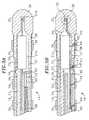
- the tip electrode 36 has a total length preferably ranging from about 4 mm to about 14 mm, more preferably from about 6 mm to about 12 mm. As depicted in FIGs. 3A, 3B and 5, the tip electrode 36 comprises an exposed region 35 at its distal end, a stem 37 at its proximal end, and a central region 38 interposed the exposed region 35 and the stem 37 .
- the exposed region 35 has a length preferably ranging from about 1.5 mm to about 4.0 mm, more preferably from about 2.0 mm to about 3.0 mm, still more preferably from about 2.3 mm to about 2.5 mm, and an outer diameter preferably ranging from about 2.0 mm to about 3.0 mm, more preferably from about 2.3 mm to about 2.5 mm.
- the exposed region has a length similar to its diameter.
- the ratio of the length to the diameter ranges from about 0.8:1 to about 1.2:1, more preferably from about 0.9:1 to about 1.1:1.
- the length of the exposed region is approximately equal to the diameter of the exposed region.
- the tip electrode preferably has a length and diameter equal to about 2.3 mm.
- the surface area of the tip electrode (having a generally hemispherical distal end) is the same in the parallel orientation and in the perpendicular orientation.
- the central region 38 has a length preferably ranging from about 2 mm to about 10 mm, more preferably from about 3 mm to about 8 mm, still more preferably from about 3.5 mm to about 6 mm.
- the outer diameter of the central region 38 is slightly less than the outer diameter of the exposed region 35 , and is preferably from about 0.1 mm to about 0.3 mm letter than less than the outer diameter of the exposed region.
- the central region 38 is provided with a covering and a ring electrode is mounted thereon.
- the outer diameter of the central region 38 is slightly less than the outer diameter of the exposed region 35
- the outer diameter of the ring electrode mounted thereon will generally correspond to the outer diameter of the exposed region.
- the outer diameter of the ring electrode (and optionally the outer diameter of the central region 38 ) can be greater than the outer diameter of the exposed region 35 .
- the stem 37 is provided for mounting of the tip electrode 36 onto the tubing 19 of the tip section 14 .
- the stem has a length preferably ranging from about 1 mm to about 4 mm, more preferably from about 1.5 mm to about 2.5 mm, still more preferably about 2.0 mm.
- the outer diameter of the stem 37 is less than the outer diameter of the central region 38 , and preferably ranging from about 1.5 mm to about 2.0.
- the dimensions of the stem 37 are not critical, so long as the stem can fit within the distal end of the tubing 19 .
- a hole is drilled into the distal end of the tubing 19 , and the proximal end of the stem 37 is glued into the hole, with polyurethane glue or the like.
- the proximal end of the stem 37 does not contact the inside of the tubing 19 so that a slot 26 is provided therebetween, to assist in the anchoring of a puller wire discussed in more detail below.
- the stem 37 can be eliminated, and the proximal end of the tip electrode 36 can be mounted onto the tubing 19 by any other suitable means known in the art.
- the distal end of the tubing 19 can be inserted into an opening in this proximal end of the tip electrode 36 , e.g., within the central region 38 , and fixed in place with glue or the like.
- the stem 37 , central region 38 , and exposed region 35 are generally solid with a blind hole 31 extending from the proximal end of the stem 37 part way into the exposed region 35 .
- the blind hole 31 comprises a proximal section 31a having a first diameter and a distal section 31b having a second diameter less than the first diameter.
- the proximal section 31a has a length preferably ranging from about 5.5 mm to 6.0 mm, more preferably about 5.7 mm, and a diameter preferably ranging from about 1.0 mm to 1.5 mm, more preferably about 1.3 mm.
- the distal section 31b preferably begins at the proximal end of the exposed region 35 and extends into the exposed region 35 a distance such that the distal end of the hole does not extend out through the distal end of the exposed region, but is preferably within about 0.5 mm of the distal end of the exposed region.
- the diameter of the distal section 31b preferably ranges from about 0.3 mm to 0.7 mm, more preferably about 0.5 mm.
- the distal section 31b is designed so that a thermocouple or the like mounted therein, as discussed in more detail below, is generally in the center of the exposed region 35 .
- the central region 38 of the tip electrode 36 is provided with an electrically insulating and thermally conductive layer 55 over at least a portion, and preferably over all, of the outer surface of the central region 38 .
- the electrically insulating and thermally conductive layer 55 is made of any suitable electrically insulating and thermally conductive material, including, but not limited to diamond, carbon, parylene, polyimide, polyester, polyurethane, epoxy, ceramic, and combinations thereof.
- the electrically insulating and thermally conductive layer 55 preferably has a thickness no greater than about 10 ⁇ m, more preferably ranging from about 0.5 ⁇ m to about 10 ⁇ m, still more preferably from about 1 ⁇ m to about 5 ⁇ m.
- the insulating layer 55 can be applied by any suitable technique.
- a layer of parylene can be applied by a deposition coating technique where the exposed region 35 of the tip electrode 36 is placed in a deposition chamber. The chamber functions to both hold the tip electrode 36 in place, as well as protect the exposed region 35 from exposure to parylene deposits.
- the insulating layer 55 may comprise a shrink-sleeve made of, for example, a thin polyester (e.g., about 0.00025 inch), or may comprise a thin coating of polyurethane or the like painted onto the surface of the central region 38 .
- a ring electrode 39 is mounted on the central portion 38 of the tip electrode 36 .
- the ring electrode 39 is slid over the electrically insulating layer 55 and fixed in place by glue or the like.
- the electrically insulating layer 55 insulates the tip electrode 36 from the ring electrode 39 .
- the ring electrode 39 can be made of any suitable electrically-conductive material, such as platinum, gold, or stainless steel, and is preferably made from a platinum-iridium alloy (90% platinum/10% iridium).
- the ring electrode 39 is mounted near the distal end of the central portion 38 in close proximity to the exposed region 35 .
- the ring electrode 39 (i.e., the distal edge of the ring electrode) is preferably spaced apart from the exposed region 35 a distance no greater than about 2 mm, more preferably from about 0.2 mm to about 1.5 mm, more preferably from about 0.2 mm to about 0.5 mm.
- the ring electrode 39 can be positioned closer to the flexible tubing 19 , in which case the ring electrode (i.e., the proximal edge of the ring electrode) is preferably spaced apart from the distal end of the tubing a distance no greater than about 2 mm.
- the ring electrode 39 has a width preferably ranging from about 0.4 mm to about 2.0 mm, more preferably from about 0.5 mm to about 1.5 mm, still more preferably from about 0.6 mm to about 1.0 mm.
- the outer diameter of the ring electrode 39 is the same as the outer diameter of the exposed region 35 of the tip electrode 36 .
- the tip electrode 36 and ring electrode 39 are each connected to a separate lead wire 44 .
- the lead wires 44 extend through the first lumen 30 of tip section 14 , the central lumen 18 of the catheter body 12 , and the control handle 16 , and terminate at their proximal end in an input jack (not shown) that may be plugged into an appropriate signal processing unit (not shown) and source of RF energy (not shown).
- the portion of the lead wires 44 extending through the central lumen 18 of the catheter body 12 , control handle 16 and proximal end of the tip section 14 may be enclosed within a protective sheath 49 , which can be made of any suitable material, preferably polyimide.
- the protective sheath 49 is preferably anchored at its distal end to the proximal end of the tip section 14 by gluing it in the first lumen 30 with polyurethane glue or the like.
- the lead wires 44 are attached to the tip electrode 36 and ring electrodes 39 by any conventional technique. Connection of a lead wire 44 to the tip electrode 36 is accomplished, for example, by soldering the lead wire 44 into a first hole 47 located along the stem 37 of the tip electrode 36 , as shown in FIG. 3B.
- Connection of a lead wire 44 to the ring electrode 39 is preferably accomplished by first making a second hole 48 through the central region 38 of the tip electrode 36 and through the insulating layer 55 . A lead wire 44 is then drawn through the hole 48 . The ends of the lead wire 44 are then stripped of any coating and soldered or welded to the underside of the ring electrode 39 , which is then slid into position over the hole 48 and fixed in place with polyurethane glue or the like.
- Two additional ring electrodes 59 are mounted of the distal end the tip section 14 .
- the ring electrodes 59 are slid over the flexible tubing 19 and fixed in place by glue of the like.
- the position and spacing of the additional ring electrode 59 are not critical. If desired, additional ring electrodes 59 may be used and can be positioned over the flexible tubing 19 of the tip section 14 in a similar manner.
- a temperature sensing means is provided for the tip electrode 36 and, if desired, the ring electrodes 39 and/or 59 . Any conventional temperature sensing means, e.g., a thermocouple or thermistor, may be used.
- a preferred temperature sensing means for the tip electrode 36 comprises a thermocouple formed by an enameled wire pair.
- One wire of the wire pair is a copper wire 41 , e.g., a number 40 copper wire.
- the other wire of the wire pair is a constantan wire 45 .
- the wires 41 and 45 of the wire pair are electrically isolated from each other except at their distal ends where they are twisted together, covered with a short piece of plastic tubing 58 , e.g., polyamide, and covered with epoxy (as shown in FIG. 3c).
- the plastic tubing 58 is then attached in the distal section 31b of the blind hole 31 in the tip electrode 36 , by polyurethane glue or the like.
- the wires 41 and 45 can be sold
- the wires 41 and 45 extend through the second lumen 32 in the tip section 14 and through the central lumen 18 of the catheter body 12 . Within the second lumen 32 and central lumen 18 , the wires 41 and 45 extend through the protective sheath 49 with the lead wires 44 . The wires 41 and 45 then extend out through the control handle 16 and to a connector (not shown) connectable to a temperature monitor (not shown).
- the temperature sensing means may be a thermistor.
- a suitable thermistor for use in the present invention is Model No. AB6N2-GC 14KA 143E/37C sold by Thermometrics (New Jersey).
- the mechanism comprises a puller wire 50 extending through the catheter body 12 .
- the puller wire 50 is anchored at its proximal end to the control handle 16 and is anchored at its distal end to the tip section 14 .
- the puller wire 50 is made of any suitable metal, such as stainless steel or Nitinol, and is preferably coated with Teflon® or the like. The coating imparts lubricity to the puller wire 50 .
- the puller wire 50 preferably has a diameter ranging from about 0.006 to about 0.010 inch.
- a compression coil 52 is situated within the catheter body 12 in surrounding relation to the puller wire 50 .
- the compression coil 52 extends from the proximal end of the catheter body 12 to the proximal end of the tip section 14 .
- the compression coil 52 is made of any suitable metal, preferably stainless steel.
- the compression coil 52 is tightly wound on itself to provide flexibility, i.e., bending, but to resist compression.
- the inner diameter of the compression coil 52 is preferably slightly larger than the diameter of the puller wire 50 .
- the Teflon® coating on the puller wire 50 allows it to slide freely within the compression coil 52 .
- the outer surface of the compression coil 52 can be covered by a flexible, non-conductive sheath 46 , e.g., made of polyimide tubing, to prevent contact between the compression coil 52 and any other wires within the catheter body 12 .
- the compression coil 52 is anchored at its proximal end to the proximal end of the stiffening tube 20 in the catheter body 12 by glue joint 51 and at its distal end to the tip section 14 by glue joint 53 .
- Both glue joints 51 and 53 preferably comprise polyurethane glue or the like.
- the glue may be applied by means of a syringe or the like through a hole made between the outer surface of the catheter body 12 and the central lumen 18 . Such a hole may be formed, for example, by a needle or the like that punctures the outer wall 22 of the catheter body 12 and the stiffening tube 20 which is heated sufficiently to form a permanent hole.
- the glue is then introduced through the hole to the outer surface of the compression coil 52 and wicks around the outer circumference to form a glue joint about the entire circumference of the compression coil 52 .
- the puller wire 50 extends into the second lumen 32 of the tip section 14 .
- the puller wire 50 is anchored at its distal end to the distal end of the tip section 14 by an anchor 54 .
- a preferred method for anchoring the puller wire 50 within the slot 26 is by soldering or welding the distal end of the puller wire 50 to an anchor 54 , preferably formed from a small section of stainless steel ribbon or the like.
- the anchor 54 is displaced inside the slot 26 between the inside of the tubing 19 and the proximal end of the stem 37 in a transverse arrangement to the puller wire, forming a T-bar or anchor. Because the length of the anchor 54 is longer than the diameter of the second lumen 32 , the anchor 54 cannot be pulled thought the lumen 32 .
- the puller wire 50 can be anchored in a blind hole in the tip electrode 36 , as described, for example, in U.S. Patent No. 6,027,473, the disclosure of which is incorporated herein by reference.
- the puller wire 42 can be anchored to the side of the tip section 14 , as described, for example, in EP-A-0 904 796, the disclosure of which is incorporated herein by reference.
- the puller wire 50 extends through a plastic, preferably Teflon®, sheath 56 , which prevents the puller wire 50 from cutting into the wall of the tubing 19 when the tip section is deflected.
- a safety wire 57 extends through the catheter body 12 and is anchored at its distal end to the tip electrode 36 .
- the safety wire 57 is preferably a Monell wire wrapped with copper.
- the safety wire 57 is anchored to the tip electrode 36 , for example, by soldering the safety wire 57 into the first hole 47 in the stem 37 .
- the safety wire 57 is wrapped around the compression coil 52 at a location within the catheter body 12 .
- An electromagnetic location sensor 72 is contained within the tip electrode 36 .
- the electromagnetic sensor 72 is located within proximal section 31a of the blind hole 31 in the tip electrode 36 and fixed by polyurethane glue or the like. Depending on the dimensions of the tip electrode 36 and sensor 72 , it may be desirable for the sensor to extend, at least in part, into the stem 37 of the tip electrode and possibly even into the distal end of the tubing 19 of the tip section.
- the electromagnetic sensor 72 is connected to an electromagnetic sensor cable 74 , which extends through the third lumen 34 of the tip section 14 , through the catheter body 12 , and out through control handle 16 .
- the electromagnetic sensor cable 74 comprises multiple wires encased within a plastic covered sheath.
- the sensor cable 74 is connected to a circuit board (not shown).
- the circuit board amplifies the signal received from the electromagnetic sensor 72 and transmits it to a computer in a form understandable by the computer.
- the circuit board contains an EPROM chip which shuts down the circuit board after the catheter has been used. This prevents the catheter, or at least the electromagnetic sensor, from being used twice.
- Suitable electromagnetic sensors for use with the present invention are described, for example, in EP-A-0 989 384 and U.S. Patent Nos. 5,558,091, 5,443,489, 5,480,422, 5,546,951, 5,568,809, and 5,391,199, the disclosures of which are incorporated herein by reference.
- the catheter can be multidirectional, i.e., having two or more puller wires to enhance the ability to manipulate the tip section in more than one direction or to form two or more different curves.
- a description of such a design is provided in EP-A-0 904 796, EP-A-0 985 423, EP-A-0 982 407, EP-A-1 005 839 and EP-A-1 038 545, the disclosures of which is incorporated herein by reference.
- the catheters in accordance with the present invention are particularly suitable for mapping the heart and ablating heart tissue, such as accessory signal pathways causing arrhythmias.
- the distal end of the catheter 10 is inserted into a vein or artery and advanced into the heart.
- the puller wire 50 and control handle 16 are used to deflect the tip section 14 .
- the electrical activity of the heart may be identified, evaluated or mapped, and electrophysiological sources of arrhythmia may be identified and/or treated.
- the bipolar electrode pair namely, the exposed region 35 of the tip electrode 36 and ring electrode 39 mounted on the tip electrode, is used to map the electrical activity of the heart.
- the close proximity of the ring electrode 39 to the exposed region 35 of the tip electrode 36 provides the catheter with more accurate bipolar mapping capabilities. Because of their close proximity, the electrodes 36 and 39 are exposed to nearly identical nosie and far-field background signals.
- a bipolar electrogram displays the difference of the two signals, so essentially only the electrical activity from the nearby tissue is recorded. Closely spaced electrodes provide more discrete electrograms.
- the electrically insulating layer 55 limits the electrically active surface area of the tip electrode 36 to the exposed region 35 , providing improved electrogram resolution compared to a conventional tip electrode. More specifically, electrograms recorded from the relatively small exposed region 35 will be more discrete, reporting electrical activity from a smaller area of tissue.
- the electromagnetic location sensor 72 in the tip section 14 of the catheter is used to provide a map of the heart so that the physician can better determine where to ablate and can have a better sense for where the tip section 14 is located during the procedure.
- the patient is placed in a magnetic field generated, for example, by situating under the patient a pad containing coils for generating a magnetic field, and a reference electromagnetic sensor is fixed relative to the patient, e.g., taped to the patient's back.
- Signals generated in the heart by both the fixed reference sensor and the electromagnetic location sensor 72 in the catheter are amplified and transmitted to a computer that analyzes the signals and displays them on a monitor.
- the precise location of the location sensor 72 (and thus the tip section 14 , including the tip electrode 36 ) relative to the reference sensor can be ascertained and visually displayed.
- the sensor 72 can also detect displacement of the catheter that is caused by contraction of the heart muscle.
- the electromagnetic mapping sensor 72 preferably is used in combination with the tip electrode 36 and ring electrode 39 .
- a physician can simultaneously map the contours or shape of the heart chamber, the electrical activity of the heart, and the extent of displacement of the catheter.
- the tip electrode 36 and ring electrode 38 are used to monitor the strength of the electrical signals at a particular location.
- the inventive tip electrode design can be effectively used without the inclusion of a location sensor, and thus the electromagnetic sensor 72 can be eliminated if desired.
- the physician uses the same catheter for ablating the heart tissue.
- the relatively large surface area of the tip electrode 36 which includes the exposed region 35 as well as the central region 38 covered with the thermally conductive layer 55 , enhances the ability of the electrode to dissipate heat during ablation compared to a comparable tip electrode having a length closer to the that of the exposed region 35 of the present catheter.
- the tip electrode of the present invention having a preferred length (outside of the plastic tubing 19 ) of about 6 mm to about 8 mm provides improved convective cooling by the passing blood, such that additional power can be applied to the tissue.
- conventional 8 mm tip electrodes require more power than the inventive tip electrode.
- the tip electrode of the present invention preferably has an exposed length of only about 2 mm to about 3 mm, reducing the amount of power required to ablate compared to a tip electrode have an exposed length of 8 mm.
- a conventional 8 mm tip electrode uses more energy heating the surrounding blood rather than heating the adjacent heart tissue. This heating of the blood can cause significant coagulation of the blood along the surface of the tip electrode.
- the present invention overcomes this problem by providing an electrically insulating, but thermally conductive layer over the non-exposed portion of the tip electrode 36 , allowing the electrical power to be concentrated at the exposed region 35 , while the insulated portion (the central region 38 ) of the tip electrode is convectively cooled by passing blood.
- the inventive electrode can create the same sized lesion as a standard tip electrode having a total length equal to the total length of the inventive electrode (but without an electrically insulating and thermally conductive covering), but using less power. This holds true because the inventive electrode has a higher current density than a standard tip electrode, while still having similar cooling capabilities, and therefore less power is needed.
- electrode impedance is routinely monitored during ablation to detect the potential formation of dangerous char or thrombus on the tip electrode. Because the electrically active area (i.e., the exposed region 35 ) of the inventive tip electrode is smaller than with conventional ablation tip electrodes that offer similar cooling ability, changes in impedance due to char or thrombus formation are more readily detected with the inventive catheter.
Landscapes
- Health & Medical Sciences (AREA)
- Life Sciences & Earth Sciences (AREA)
- Surgery (AREA)
- Engineering & Computer Science (AREA)
- Plasma & Fusion (AREA)
- Medical Informatics (AREA)
- Otolaryngology (AREA)
- Physics & Mathematics (AREA)
- Cardiology (AREA)
- Biomedical Technology (AREA)
- Heart & Thoracic Surgery (AREA)
- Nuclear Medicine, Radiotherapy & Molecular Imaging (AREA)
- Molecular Biology (AREA)
- Animal Behavior & Ethology (AREA)
- General Health & Medical Sciences (AREA)
- Public Health (AREA)
- Veterinary Medicine (AREA)
- Surgical Instruments (AREA)
- Media Introduction/Drainage Providing Device (AREA)
Applications Claiming Priority (2)
| Application Number | Priority Date | Filing Date | Title |
|---|---|---|---|
| US611617 | 1984-05-18 | ||
| US09/611,617 US6477396B1 (en) | 2000-07-07 | 2000-07-07 | Mapping and ablation catheter |
Publications (2)
| Publication Number | Publication Date |
|---|---|
| EP1169972A1 true EP1169972A1 (de) | 2002-01-09 |
| EP1169972B1 EP1169972B1 (de) | 2006-01-18 |
Family
ID=24449742
Family Applications (1)
| Application Number | Title | Priority Date | Filing Date |
|---|---|---|---|
| EP01305844A Expired - Lifetime EP1169972B1 (de) | 2000-07-07 | 2001-07-06 | Ablationskartierungskatheter |
Country Status (3)
| Country | Link |
|---|---|
| US (1) | US6477396B1 (de) |
| EP (1) | EP1169972B1 (de) |
| DE (1) | DE60116715T2 (de) |
Cited By (19)
| Publication number | Priority date | Publication date | Assignee | Title |
|---|---|---|---|---|
| WO2003034932A1 (en) * | 2001-10-22 | 2003-05-01 | Boston Scientific Limited | Liquid cooled rf coagulation catheter |
| US6579288B1 (en) | 1997-10-10 | 2003-06-17 | Scimed Life Systems, Inc. | Fluid cooled apparatus for supporting diagnostic and therapeutic elements in contact with tissue |
| US6942661B2 (en) | 2000-08-30 | 2005-09-13 | Boston Scientific Scimed, Inc. | Fluid cooled apparatus for supporting diagnostic and therapeutic elements in contact with tissue |
| US7371233B2 (en) | 2004-02-19 | 2008-05-13 | Boston Scientific Scimed, Inc. | Cooled probes and apparatus for maintaining contact between cooled probes and tissue |
| US7421299B2 (en) | 2002-12-13 | 2008-09-02 | W.C. Heraeus Gmbh & Co. Kg | Stimulation electrode and methods of making and using same |
| US7608072B2 (en) | 2003-12-02 | 2009-10-27 | Boston Scientific Scimed, Inc. | Surgical methods and apparatus for maintaining contact between tissue and electrophysiology elements and confirming whether a therapeutic lesion has been formed |
| US7704248B2 (en) | 2005-12-21 | 2010-04-27 | Boston Scientific Scimed, Inc. | Ablation device with compression balloon |
| US8016822B2 (en) | 2005-05-28 | 2011-09-13 | Boston Scientific Scimed, Inc. | Fluid injecting devices and methods and apparatus for maintaining contact between fluid injecting devices and tissue |
| US8052676B2 (en) | 2003-12-02 | 2011-11-08 | Boston Scientific Scimed, Inc. | Surgical methods and apparatus for stimulating tissue |
| WO2013173481A3 (en) * | 2012-05-18 | 2014-01-16 | Holaira, Inc. | Compact delivery pulmonary treatment systems and methods for improving pulmonary function |
| WO2014028191A1 (en) * | 2012-08-17 | 2014-02-20 | Medtronic Ablation Frontiers Llc | Electrophysiology catheter design |
| US9414883B2 (en) | 2006-06-09 | 2016-08-16 | Boston Scientific Scimed, Inc. | Co-access foam/electrode introducer |
| EP3191003A4 (de) * | 2015-01-07 | 2018-05-16 | St. Jude Medical, Cardiology Division, Inc. | Ablationskatheter mit elektroden |
| EP3220844A4 (de) * | 2014-11-19 | 2018-08-01 | Advanced Cardiac Therapeutics, Inc. | Systeme und verfahren für hochauflösende gewebekartierung |
| US10149714B2 (en) | 2008-05-09 | 2018-12-11 | Nuvaira, Inc. | Systems, assemblies, and methods for treating a bronchial tree |
| US10383686B2 (en) | 2014-11-19 | 2019-08-20 | Epix Therapeutics, Inc. | Ablation systems with multiple temperature sensors |
| US10888373B2 (en) | 2017-04-27 | 2021-01-12 | Epix Therapeutics, Inc. | Contact assessment between an ablation catheter and tissue |
| US11058879B2 (en) | 2008-02-15 | 2021-07-13 | Nuvaira, Inc. | System and method for bronchial dilation |
| US11389233B2 (en) | 2009-11-11 | 2022-07-19 | Nuvaira, Inc. | Systems, apparatuses, and methods for treating tissue and controlling stenosis |
Families Citing this family (134)
| Publication number | Priority date | Publication date | Assignee | Title |
|---|---|---|---|---|
| US6161543A (en) | 1993-02-22 | 2000-12-19 | Epicor, Inc. | Methods of epicardial ablation for creating a lesion around the pulmonary veins |
| US5897553A (en) | 1995-11-02 | 1999-04-27 | Medtronic, Inc. | Ball point fluid-assisted electrocautery device |
| US6409722B1 (en) | 1998-07-07 | 2002-06-25 | Medtronic, Inc. | Apparatus and method for creating, maintaining, and controlling a virtual electrode used for the ablation of tissue |
| NL1003024C2 (nl) | 1996-05-03 | 1997-11-06 | Tjong Hauw Sie | Prikkelgeleidingsblokkeringsinstrument. |
| US6311692B1 (en) | 1996-10-22 | 2001-11-06 | Epicor, Inc. | Apparatus and method for diagnosis and therapy of electrophysiological disease |
| US6840936B2 (en) | 1996-10-22 | 2005-01-11 | Epicor Medical, Inc. | Methods and devices for ablation |
| US6719755B2 (en) | 1996-10-22 | 2004-04-13 | Epicor Medical, Inc. | Methods and devices for ablation |
| US6805128B1 (en) | 1996-10-22 | 2004-10-19 | Epicor Medical, Inc. | Apparatus and method for ablating tissue |
| US7052493B2 (en) | 1996-10-22 | 2006-05-30 | Epicor Medical, Inc. | Methods and devices for ablation |
| US6096037A (en) | 1997-07-29 | 2000-08-01 | Medtronic, Inc. | Tissue sealing electrosurgery device and methods of sealing tissue |
| US8709007B2 (en) | 1997-10-15 | 2014-04-29 | St. Jude Medical, Atrial Fibrillation Division, Inc. | Devices and methods for ablating cardiac tissue |
| US6706039B2 (en) | 1998-07-07 | 2004-03-16 | Medtronic, Inc. | Method and apparatus for creating a bi-polar virtual electrode used for the ablation of tissue |
| US6537248B2 (en) | 1998-07-07 | 2003-03-25 | Medtronic, Inc. | Helical needle apparatus for creating a virtual electrode used for the ablation of tissue |
| US8308719B2 (en) | 1998-09-21 | 2012-11-13 | St. Jude Medical, Atrial Fibrillation Division, Inc. | Apparatus and method for ablating tissue |
| AU775394B2 (en) | 1999-07-19 | 2004-07-29 | St. Jude Medical, Atrial Fibrillation Division, Inc. | Apparatus and method for ablating tissue |
| US7706882B2 (en) | 2000-01-19 | 2010-04-27 | Medtronic, Inc. | Methods of using high intensity focused ultrasound to form an ablated tissue area |
| US6447443B1 (en) | 2001-01-13 | 2002-09-10 | Medtronic, Inc. | Method for organ positioning and stabilization |
| US8241274B2 (en) | 2000-01-19 | 2012-08-14 | Medtronic, Inc. | Method for guiding a medical device |
| US6692450B1 (en) | 2000-01-19 | 2004-02-17 | Medtronic Xomed, Inc. | Focused ultrasound ablation devices having selectively actuatable ultrasound emitting elements and methods of using the same |
| US8221402B2 (en) | 2000-01-19 | 2012-07-17 | Medtronic, Inc. | Method for guiding a medical device |
| US8048070B2 (en) | 2000-03-06 | 2011-11-01 | Salient Surgical Technologies, Inc. | Fluid-assisted medical devices, systems and methods |
| US6514250B1 (en) | 2000-04-27 | 2003-02-04 | Medtronic, Inc. | Suction stabilized epicardial ablation devices |
| US6488680B1 (en) | 2000-04-27 | 2002-12-03 | Medtronic, Inc. | Variable length electrodes for delivery of irrigated ablation |
| WO2001082812A1 (en) | 2000-04-27 | 2001-11-08 | Medtronic, Inc. | Vibration sensitive ablation apparatus and method |
| US6926669B1 (en) | 2000-10-10 | 2005-08-09 | Medtronic, Inc. | Heart wall ablation/mapping catheter and method |
| US20040138621A1 (en) | 2003-01-14 | 2004-07-15 | Jahns Scott E. | Devices and methods for interstitial injection of biologic agents into tissue |
| US7628780B2 (en) | 2001-01-13 | 2009-12-08 | Medtronic, Inc. | Devices and methods for interstitial injection of biologic agents into tissue |
| US7740623B2 (en) | 2001-01-13 | 2010-06-22 | Medtronic, Inc. | Devices and methods for interstitial injection of biologic agents into tissue |
| US6648883B2 (en) | 2001-04-26 | 2003-11-18 | Medtronic, Inc. | Ablation system and method of use |
| US7959626B2 (en) | 2001-04-26 | 2011-06-14 | Medtronic, Inc. | Transmural ablation systems and methods |
| US6663627B2 (en) | 2001-04-26 | 2003-12-16 | Medtronic, Inc. | Ablation system and method of use |
| US6807968B2 (en) | 2001-04-26 | 2004-10-26 | Medtronic, Inc. | Method and system for treatment of atrial tachyarrhythmias |
| US7250048B2 (en) | 2001-04-26 | 2007-07-31 | Medtronic, Inc. | Ablation system and method of use |
| EP2275050A1 (de) | 2001-09-05 | 2011-01-19 | Salient Surgical Technologies, Inc. | Flüssigkeitsgestützte elektrochirurgische Vorrichtungen, Verfahren und Systeme |
| US20040230283A1 (en) * | 2001-11-29 | 2004-11-18 | Medtronic, Inc. | Trans-septal pacing method and apparatus |
| US6656175B2 (en) | 2001-12-11 | 2003-12-02 | Medtronic, Inc. | Method and system for treatment of atrial tachyarrhythmias |
| US7967816B2 (en) | 2002-01-25 | 2011-06-28 | Medtronic, Inc. | Fluid-assisted electrosurgical instrument with shapeable electrode |
| US6827715B2 (en) | 2002-01-25 | 2004-12-07 | Medtronic, Inc. | System and method of performing an electrosurgical procedure |
| DE10212841B4 (de) * | 2002-03-22 | 2011-02-24 | Karl Storz Gmbh & Co. Kg | Medizinisches Instrument zur Behandlung von Gewebe mittels Hochfrequenzstrom sowie medizinisches System mit einem derartigen medizinischen Instrument |
| US7294143B2 (en) | 2002-05-16 | 2007-11-13 | Medtronic, Inc. | Device and method for ablation of cardiac tissue |
| US7118566B2 (en) | 2002-05-16 | 2006-10-10 | Medtronic, Inc. | Device and method for needle-less interstitial injection of fluid for ablation of cardiac tissue |
| US20040082947A1 (en) | 2002-10-25 | 2004-04-29 | The Regents Of The University Of Michigan | Ablation catheters |
| US7083620B2 (en) | 2002-10-30 | 2006-08-01 | Medtronic, Inc. | Electrosurgical hemostat |
| US6922579B2 (en) * | 2002-12-12 | 2005-07-26 | Scimed Life Systems, Inc. | La placian electrode |
| US7497857B2 (en) | 2003-04-29 | 2009-03-03 | Medtronic, Inc. | Endocardial dispersive electrode for use with a monopolar RF ablation pen |
| US8333764B2 (en) | 2004-05-12 | 2012-12-18 | Medtronic, Inc. | Device and method for determining tissue thickness and creating cardiac ablation lesions |
| WO2005112812A1 (en) | 2004-05-14 | 2005-12-01 | Medtronic, Inc. | Method and devices for treating atrial fibrillation by mass ablation |
| WO2005120374A1 (en) | 2004-06-02 | 2005-12-22 | Medtronic, Inc. | Compound bipolar ablation device and method |
| EP1750608B1 (de) | 2004-06-02 | 2012-10-03 | Medtronic, Inc. | Ablationsvorrichtung mit backen |
| WO2005120377A1 (en) | 2004-06-02 | 2005-12-22 | Medtronic, Inc. | Clamping ablation tool |
| EP1750607A2 (de) | 2004-06-02 | 2007-02-14 | Medtronic, Inc. | Schlaufenablationsgerät und verfahren |
| US8926635B2 (en) | 2004-06-18 | 2015-01-06 | Medtronic, Inc. | Methods and devices for occlusion of an atrial appendage |
| US8663245B2 (en) | 2004-06-18 | 2014-03-04 | Medtronic, Inc. | Device for occlusion of a left atrial appendage |
| US8409219B2 (en) | 2004-06-18 | 2013-04-02 | Medtronic, Inc. | Method and system for placement of electrical lead inside heart |
| US20060089637A1 (en) | 2004-10-14 | 2006-04-27 | Werneth Randell L | Ablation catheter |
| US8617152B2 (en) | 2004-11-15 | 2013-12-31 | Medtronic Ablation Frontiers Llc | Ablation system with feedback |
| MX2007005891A (es) * | 2004-11-15 | 2007-11-23 | Johnson & Johnson | Cateter con detector de temperatura microfabricado. |
| WO2006055658A1 (en) * | 2004-11-15 | 2006-05-26 | Biosense Webster Inc. | Catheter with multiple microfabricated temperature sensors |
| US7468062B2 (en) | 2004-11-24 | 2008-12-23 | Ablation Frontiers, Inc. | Atrial ablation catheter adapted for treatment of septal wall arrhythmogenic foci and method of use |
| US7429261B2 (en) | 2004-11-24 | 2008-09-30 | Ablation Frontiers, Inc. | Atrial ablation catheter and method of use |
| EP3804647A1 (de) | 2005-04-21 | 2021-04-14 | Boston Scientific Scimed Inc. | Steuerungsverfahren und -vorrichtungen zur energieversorgung |
| US8932208B2 (en) | 2005-05-26 | 2015-01-13 | Maquet Cardiovascular Llc | Apparatus and methods for performing minimally-invasive surgical procedures |
| EP1895927A4 (de) | 2005-06-20 | 2011-03-09 | Medtronic Ablation Frontiers | Ablationskatheter |
| CA2615267A1 (en) | 2005-07-11 | 2007-01-18 | Ablation Frontiers, Inc. | Low power tissue ablation system |
| US8657814B2 (en) | 2005-08-22 | 2014-02-25 | Medtronic Ablation Frontiers Llc | User interface for tissue ablation system |
| US7623899B2 (en) * | 2005-09-16 | 2009-11-24 | Biosense Webster, Inc. | Catheter with flexible pre-shaped tip section |
| US8355801B2 (en) * | 2005-09-26 | 2013-01-15 | Biosense Webster, Inc. | System and method for measuring esophagus proximity |
| US8273016B2 (en) * | 2006-03-10 | 2012-09-25 | Biosense Webster, Inc. | Esophagus isolation device |
| US20080039746A1 (en) | 2006-05-25 | 2008-02-14 | Medtronic, Inc. | Methods of using high intensity focused ultrasound to form an ablated tissue area containing a plurality of lesions |
| US8641704B2 (en) | 2007-05-11 | 2014-02-04 | Medtronic Ablation Frontiers Llc | Ablation therapy system and method for treating continuous atrial fibrillation |
| EP2209517A4 (de) | 2007-10-05 | 2011-03-30 | Maquet Cardiovascular Llc | Vorrichtungen und verfahren für minimal invasive chirurgische eingriffe |
| US8118809B2 (en) * | 2007-12-21 | 2012-02-21 | St. Jude Medical, Atrial Fibrillation Division, Inc. | Flexible conductive polymer electrode and method for ablation |
| EP2227174B1 (de) | 2007-12-28 | 2019-05-01 | Salient Surgical Technologies, Inc. | Flüssigkeitsgestützte elektrochirurgische vorrichtung |
| US20090198093A1 (en) * | 2008-02-06 | 2009-08-06 | Oliver Meissner | System and method for combined embolization and ablation therapy |
| EP2303171A2 (de) | 2008-05-13 | 2011-04-06 | Medtronic, Inc. | Untersuchung von gewebeläsionen |
| US9254168B2 (en) | 2009-02-02 | 2016-02-09 | Medtronic Advanced Energy Llc | Electro-thermotherapy of tissue using penetrating microelectrode array |
| US8632533B2 (en) | 2009-02-23 | 2014-01-21 | Medtronic Advanced Energy Llc | Fluid-assisted electrosurgical device |
| US8910376B2 (en) * | 2009-05-27 | 2014-12-16 | Boston Scientific Neuromodulation Corporation | Systems and methods for forming an end of an elongated member of an electrical stimulation system |
| US8926605B2 (en) | 2012-02-07 | 2015-01-06 | Advanced Cardiac Therapeutics, Inc. | Systems and methods for radiometrically measuring temperature during tissue ablation |
| US9277961B2 (en) | 2009-06-12 | 2016-03-08 | Advanced Cardiac Therapeutics, Inc. | Systems and methods of radiometrically determining a hot-spot temperature of tissue being treated |
| US8954161B2 (en) | 2012-06-01 | 2015-02-10 | Advanced Cardiac Therapeutics, Inc. | Systems and methods for radiometrically measuring temperature and detecting tissue contact prior to and during tissue ablation |
| US9226791B2 (en) | 2012-03-12 | 2016-01-05 | Advanced Cardiac Therapeutics, Inc. | Systems for temperature-controlled ablation using radiometric feedback |
| US10080482B2 (en) | 2009-06-30 | 2018-09-25 | Intuitive Surgical Operations, Inc. | Compliant surgical device |
| IN2012DN01917A (de) | 2009-09-08 | 2015-07-24 | Salient Surgical Tech Inc | |
| WO2011112991A1 (en) | 2010-03-11 | 2011-09-15 | Salient Surgical Technologies, Inc. | Bipolar electrosurgical cutter with position insensitive return electrode contact |
| US9820803B2 (en) | 2010-04-28 | 2017-11-21 | Medtronic, Inc. | Subxiphoid connective lesion ablation system and method |
| US20110295249A1 (en) * | 2010-05-28 | 2011-12-01 | Salient Surgical Technologies, Inc. | Fluid-Assisted Electrosurgical Devices, and Methods of Manufacture Thereof |
| EP2581058B1 (de) * | 2010-06-08 | 2016-03-23 | Toray Industries, Inc. | Katheter zum messen eines elektrischen potentials |
| US9138289B2 (en) | 2010-06-28 | 2015-09-22 | Medtronic Advanced Energy Llc | Electrode sheath for electrosurgical device |
| US8906012B2 (en) | 2010-06-30 | 2014-12-09 | Medtronic Advanced Energy Llc | Electrosurgical devices with wire electrode |
| US8920417B2 (en) | 2010-06-30 | 2014-12-30 | Medtronic Advanced Energy Llc | Electrosurgical devices and methods of use thereof |
| US8794830B2 (en) | 2010-10-13 | 2014-08-05 | Biosense Webster, Inc. | Catheter with digitized temperature measurement in control handle |
| US9023040B2 (en) | 2010-10-26 | 2015-05-05 | Medtronic Advanced Energy Llc | Electrosurgical cutting devices |
| WO2014141105A1 (en) | 2013-03-12 | 2014-09-18 | Baylis Medical Company Inc. | Medical device having a support structure |
| US10765473B2 (en) | 2010-11-08 | 2020-09-08 | Baylis Medical Company Inc. | Electrosurgical device having a lumen |
| US9427281B2 (en) | 2011-03-11 | 2016-08-30 | Medtronic Advanced Energy Llc | Bronchoscope-compatible catheter provided with electrosurgical device |
| EP3498208A1 (de) | 2011-04-12 | 2019-06-19 | Thermedical, Inc. | Vorrichtungen zum erwärmen eines fluids in einer fluidunterstützten ablationstherapie |
| US9750565B2 (en) | 2011-09-30 | 2017-09-05 | Medtronic Advanced Energy Llc | Electrosurgical balloons |
| WO2013052066A1 (en) * | 2011-10-07 | 2013-04-11 | Advanced Bionics Ag | Lead body with tubes of different diameters for a cochlear implant |
| US8870864B2 (en) | 2011-10-28 | 2014-10-28 | Medtronic Advanced Energy Llc | Single instrument electrosurgery apparatus and its method of use |
| US9226792B2 (en) | 2012-06-12 | 2016-01-05 | Medtronic Advanced Energy Llc | Debridement device and method |
| US10022176B2 (en) | 2012-08-15 | 2018-07-17 | Thermedical, Inc. | Low profile fluid enhanced ablation therapy devices and methods |
| US11234760B2 (en) | 2012-10-05 | 2022-02-01 | Medtronic Advanced Energy Llc | Electrosurgical device for cutting and removing tissue |
| WO2014098246A1 (en) * | 2012-12-20 | 2014-06-26 | Olympus Corporation | Position detection sensor and manipulator |
| US9044156B2 (en) | 2012-12-28 | 2015-06-02 | Biosense Webster (Israel) Ltd. | Catheter with improved safety line for distal tip and related method |
| US11937873B2 (en) | 2013-03-12 | 2024-03-26 | Boston Scientific Medical Device Limited | Electrosurgical device having a lumen |
| US9033972B2 (en) | 2013-03-15 | 2015-05-19 | Thermedical, Inc. | Methods and devices for fluid enhanced microwave ablation therapy |
| US9610396B2 (en) | 2013-03-15 | 2017-04-04 | Thermedical, Inc. | Systems and methods for visualizing fluid enhanced ablation therapy |
| US10631914B2 (en) | 2013-09-30 | 2020-04-28 | Covidien Lp | Bipolar electrosurgical instrument with movable electrode and related systems and methods |
| CN108742830A (zh) | 2013-10-28 | 2018-11-06 | 圣犹达医疗用品心脏病学部门有限公司 | 具有增强诊断能力的消融导管设计以及方法 |
| US10314647B2 (en) | 2013-12-23 | 2019-06-11 | Medtronic Advanced Energy Llc | Electrosurgical cutting instrument |
| US10813686B2 (en) | 2014-02-26 | 2020-10-27 | Medtronic Advanced Energy Llc | Electrosurgical cutting instrument |
| US9974599B2 (en) | 2014-08-15 | 2018-05-22 | Medtronic Ps Medical, Inc. | Multipurpose electrosurgical device |
| US9956029B2 (en) | 2014-10-31 | 2018-05-01 | Medtronic Advanced Energy Llc | Telescoping device with saline irrigation line |
| EP3220841B1 (de) | 2014-11-19 | 2023-01-25 | EPiX Therapeutics, Inc. | Hochauflösende abbildung von gewebe mit schrittmachertherapie |
| AU2016219980B2 (en) | 2015-02-18 | 2020-09-03 | Medtronic Xomed, Inc. | RF energy enabled tissue debridement device |
| US10376302B2 (en) | 2015-02-18 | 2019-08-13 | Medtronic Xomed, Inc. | Rotating electrical connector for RF energy enabled tissue debridement device |
| US10188456B2 (en) | 2015-02-18 | 2019-01-29 | Medtronic Xomed, Inc. | Electrode assembly for RF energy enabled tissue debridement device |
| US9636164B2 (en) | 2015-03-25 | 2017-05-02 | Advanced Cardiac Therapeutics, Inc. | Contact sensing systems and methods |
| WO2016161209A1 (en) | 2015-03-31 | 2016-10-06 | St. Jude Medical, Cardiology Division, Inc. | Methods and devices for delivering pulsed rf energy during catheter ablation |
| US11389227B2 (en) | 2015-08-20 | 2022-07-19 | Medtronic Advanced Energy Llc | Electrosurgical device with multivariate control |
| US11051875B2 (en) | 2015-08-24 | 2021-07-06 | Medtronic Advanced Energy Llc | Multipurpose electrosurgical device |
| US10716612B2 (en) | 2015-12-18 | 2020-07-21 | Medtronic Advanced Energy Llc | Electrosurgical device with multiple monopolar electrode assembly |
| SG11201807618QA (en) | 2016-03-15 | 2018-10-30 | Epix Therapeutics Inc | Improved devices, systems and methods for irrigated ablation |
| US9743984B1 (en) | 2016-08-11 | 2017-08-29 | Thermedical, Inc. | Devices and methods for delivering fluid to tissue during ablation therapy |
| US11246658B2 (en) | 2016-10-04 | 2022-02-15 | St. Jude Medical, Cardiology Division, Inc. | Ablation catheter tip |
| US11369301B2 (en) * | 2017-01-27 | 2022-06-28 | Medtronic Cryocath Lp | Highly flexible mapping and treatment device |
| US11304622B2 (en) * | 2017-02-14 | 2022-04-19 | St. Jude Medical, Cardiology Division, Inc. | System and apparatus for detecting catheters relative to introducers |
| US12023082B2 (en) | 2017-10-06 | 2024-07-02 | Medtronic Advanced Energy Llc | Hemostatic thermal sealer |
| US11083871B2 (en) | 2018-05-03 | 2021-08-10 | Thermedical, Inc. | Selectively deployable catheter ablation devices |
| US11918277B2 (en) | 2018-07-16 | 2024-03-05 | Thermedical, Inc. | Inferred maximum temperature monitoring for irrigated ablation therapy |
| WO2020194474A1 (ja) * | 2019-03-25 | 2020-10-01 | 日本ライフライン株式会社 | カテーテル |
| EP4676586A1 (de) * | 2023-03-10 | 2026-01-14 | The Children's Medical Center Corporation | Multielektrodenanordnung für intraoperative endokardiale leitungskartierung |
| US20250177055A1 (en) * | 2023-11-30 | 2025-06-05 | Biosense Webster (Israel) Ltd. | Medical probe for navigating small diameter blood vessels |
Citations (7)
| Publication number | Priority date | Publication date | Assignee | Title |
|---|---|---|---|---|
| US5257635A (en) * | 1988-11-25 | 1993-11-02 | Sensor Electronics, Inc. | Electrical heating catheter |
| US5443489A (en) | 1993-07-20 | 1995-08-22 | Biosense, Inc. | Apparatus and method for ablation |
| US5545161A (en) * | 1992-12-01 | 1996-08-13 | Cardiac Pathways Corporation | Catheter for RF ablation having cooled electrode with electrically insulated sleeve |
| US5558091A (en) | 1993-10-06 | 1996-09-24 | Biosense, Inc. | Magnetic determination of position and orientation |
| EP0904796A2 (de) | 1997-09-05 | 1999-03-31 | Cordis Webster, Inc. | Multidirektionaler lenkbarer Katheter |
| US6027473A (en) | 1997-09-05 | 2000-02-22 | Cordis Webster, Inc. | Handle for steerable DMR catheter |
| EP0989384A2 (de) | 1998-09-24 | 2000-03-29 | Biosense, Inc. | Miniaturpositionsfühler |
Family Cites Families (21)
| Publication number | Priority date | Publication date | Assignee | Title |
|---|---|---|---|---|
| US4444195A (en) | 1981-11-02 | 1984-04-24 | Cordis Corporation | Cardiac lead having multiple ring electrodes |
| US4481953A (en) | 1981-11-12 | 1984-11-13 | Cordis Corporation | Endocardial lead having helically wound ribbon electrode |
| US4966597A (en) | 1988-11-04 | 1990-10-30 | Cosman Eric R | Thermometric cardiac tissue ablation electrode with ultra-sensitive temperature detection |
| US5230349A (en) | 1988-11-25 | 1993-07-27 | Sensor Electronics, Inc. | Electrical heating catheter |
| US5749914A (en) | 1989-01-06 | 1998-05-12 | Advanced Coronary Intervention | Catheter for obstructed stent |
| US5179952A (en) | 1990-08-13 | 1993-01-19 | Arzco Medical Electronics Inc. | Electrocardial stimulator probe |
| US5085659A (en) | 1990-11-21 | 1992-02-04 | Everest Medical Corporation | Biopsy device with bipolar coagulation capability |
| US5315996A (en) | 1991-02-15 | 1994-05-31 | Lundquist Ingemar H | Torquable catheter and method |
| CA2109793A1 (en) | 1991-05-24 | 1992-12-10 | Stuart D. Edwards | Combination monophasic action potential/ablation catheter and high-performance filter system |
| US5383922A (en) | 1993-03-15 | 1995-01-24 | Medtronic, Inc. | RF lead fixation and implantable lead |
| US5462544A (en) | 1993-05-05 | 1995-10-31 | Energy Life System Corporation | Continuous heart tissue mapping and lasing catheter |
| CA2164860C (en) | 1993-06-10 | 2005-09-06 | Mir A. Imran | Transurethral radio frequency ablation apparatus |
| US5810802A (en) | 1994-08-08 | 1998-09-22 | E.P. Technologies, Inc. | Systems and methods for controlling tissue ablation using multiple temperature sensing elements |
| US5967976A (en) | 1994-08-19 | 1999-10-19 | Novoste Corporation | Apparatus and methods for procedures related to the electrophysiology of the heart |
| EP0957792A4 (de) | 1995-05-02 | 2000-09-20 | Heart Rhythm Tech Inc | Anordnung zur steuerung einem patienten zugeführten ablationsenergie |
| US5782760A (en) | 1995-05-23 | 1998-07-21 | Cardima, Inc. | Over-the-wire EP catheter |
| US5891027A (en) | 1996-10-21 | 1999-04-06 | Irvine Biomedical, Inc. | Cardiovascular catheter system with an inflatable soft tip |
| US5782900A (en) | 1997-06-23 | 1998-07-21 | Irvine Biomedical, Inc. | Catheter system having safety means |
| US6024739A (en) * | 1997-09-05 | 2000-02-15 | Cordis Webster, Inc. | Method for detecting and revascularizing ischemic myocardial tissue |
| US5919222A (en) | 1998-01-06 | 1999-07-06 | Medtronic Inc. | Adjustable medical electrode lead |
| US6171275B1 (en) * | 1998-12-03 | 2001-01-09 | Cordis Webster, Inc. | Irrigated split tip electrode catheter |
-
2000
- 2000-07-07 US US09/611,617 patent/US6477396B1/en not_active Expired - Fee Related
-
2001
- 2001-07-06 DE DE60116715T patent/DE60116715T2/de not_active Expired - Fee Related
- 2001-07-06 EP EP01305844A patent/EP1169972B1/de not_active Expired - Lifetime
Patent Citations (10)
| Publication number | Priority date | Publication date | Assignee | Title |
|---|---|---|---|---|
| US5257635A (en) * | 1988-11-25 | 1993-11-02 | Sensor Electronics, Inc. | Electrical heating catheter |
| US5545161A (en) * | 1992-12-01 | 1996-08-13 | Cardiac Pathways Corporation | Catheter for RF ablation having cooled electrode with electrically insulated sleeve |
| US5443489A (en) | 1993-07-20 | 1995-08-22 | Biosense, Inc. | Apparatus and method for ablation |
| US5480422A (en) | 1993-07-20 | 1996-01-02 | Biosense, Inc. | Apparatus for treating cardiac arrhythmias |
| US5546951A (en) | 1993-07-20 | 1996-08-20 | Biosense, Inc. | Method and apparatus for studying cardiac arrhythmias |
| US5568809A (en) | 1993-07-20 | 1996-10-29 | Biosense, Inc. | Apparatus and method for intrabody mapping |
| US5558091A (en) | 1993-10-06 | 1996-09-24 | Biosense, Inc. | Magnetic determination of position and orientation |
| EP0904796A2 (de) | 1997-09-05 | 1999-03-31 | Cordis Webster, Inc. | Multidirektionaler lenkbarer Katheter |
| US6027473A (en) | 1997-09-05 | 2000-02-22 | Cordis Webster, Inc. | Handle for steerable DMR catheter |
| EP0989384A2 (de) | 1998-09-24 | 2000-03-29 | Biosense, Inc. | Miniaturpositionsfühler |
Cited By (41)
| Publication number | Priority date | Publication date | Assignee | Title |
|---|---|---|---|---|
| US6579288B1 (en) | 1997-10-10 | 2003-06-17 | Scimed Life Systems, Inc. | Fluid cooled apparatus for supporting diagnostic and therapeutic elements in contact with tissue |
| US6942661B2 (en) | 2000-08-30 | 2005-09-13 | Boston Scientific Scimed, Inc. | Fluid cooled apparatus for supporting diagnostic and therapeutic elements in contact with tissue |
| US7303558B2 (en) | 2000-08-30 | 2007-12-04 | Boston Scientific Scimed, Inc. | Fluid cooled apparatus for supporting diagnostic and therapeutic elements in contact with tissue |
| WO2003034932A1 (en) * | 2001-10-22 | 2003-05-01 | Boston Scientific Limited | Liquid cooled rf coagulation catheter |
| US6939350B2 (en) | 2001-10-22 | 2005-09-06 | Boston Scientific Scimed, Inc. | Apparatus for supporting diagnostic and therapeutic elements in contact with tissue including electrode cooling device |
| US7421299B2 (en) | 2002-12-13 | 2008-09-02 | W.C. Heraeus Gmbh & Co. Kg | Stimulation electrode and methods of making and using same |
| US7871662B2 (en) | 2002-12-13 | 2011-01-18 | W.C. Heraeus Gmbh | Method for producing a stimulation electrode |
| US8298608B2 (en) | 2002-12-13 | 2012-10-30 | Heraeus Precious Metals Gmbh & Co. Kg | Method for producing a stimulation electrode |
| US7608072B2 (en) | 2003-12-02 | 2009-10-27 | Boston Scientific Scimed, Inc. | Surgical methods and apparatus for maintaining contact between tissue and electrophysiology elements and confirming whether a therapeutic lesion has been formed |
| US8052676B2 (en) | 2003-12-02 | 2011-11-08 | Boston Scientific Scimed, Inc. | Surgical methods and apparatus for stimulating tissue |
| US7371233B2 (en) | 2004-02-19 | 2008-05-13 | Boston Scientific Scimed, Inc. | Cooled probes and apparatus for maintaining contact between cooled probes and tissue |
| US8016822B2 (en) | 2005-05-28 | 2011-09-13 | Boston Scientific Scimed, Inc. | Fluid injecting devices and methods and apparatus for maintaining contact between fluid injecting devices and tissue |
| US7704248B2 (en) | 2005-12-21 | 2010-04-27 | Boston Scientific Scimed, Inc. | Ablation device with compression balloon |
| US7959631B2 (en) | 2005-12-21 | 2011-06-14 | Boston Scientific Scimed, Inc. | Ablation device with compression balloon |
| US9414883B2 (en) | 2006-06-09 | 2016-08-16 | Boston Scientific Scimed, Inc. | Co-access foam/electrode introducer |
| US11058879B2 (en) | 2008-02-15 | 2021-07-13 | Nuvaira, Inc. | System and method for bronchial dilation |
| US12357827B2 (en) | 2008-02-15 | 2025-07-15 | Nuvaira, Inc. | System and method for bronchial dilation |
| US11937868B2 (en) | 2008-05-09 | 2024-03-26 | Nuvaira, Inc. | Systems, assemblies, and methods for treating a bronchial tree |
| US10149714B2 (en) | 2008-05-09 | 2018-12-11 | Nuvaira, Inc. | Systems, assemblies, and methods for treating a bronchial tree |
| US12290309B2 (en) | 2009-11-11 | 2025-05-06 | Nuvaira, Inc. | Systems, apparatuses, and methods for treating tissue and controlling stenosis |
| US11389233B2 (en) | 2009-11-11 | 2022-07-19 | Nuvaira, Inc. | Systems, apparatuses, and methods for treating tissue and controlling stenosis |
| EP3639781A1 (de) * | 2012-05-18 | 2020-04-22 | Nuvaira, Inc. | Systeme, vorrichtungen und verfahren zur gewebebehandlung und stenosekontrolle |
| CN115191923A (zh) * | 2012-05-18 | 2022-10-18 | 努瓦拉公司 | 紧凑传送的肺部治疗系统和改善肺部功能的方法 |
| WO2013173481A3 (en) * | 2012-05-18 | 2014-01-16 | Holaira, Inc. | Compact delivery pulmonary treatment systems and methods for improving pulmonary function |
| EP4378523A3 (de) * | 2012-05-18 | 2024-07-31 | Nuvaira, Inc. | Systeme und vorrichtungen zur gewebebehandlung und stenosekontrolle |
| US12102436B2 (en) | 2012-08-17 | 2024-10-01 | Medtronic Ablation Frontiers Llc | Electrophysiology catheter design |
| US10039467B2 (en) | 2012-08-17 | 2018-08-07 | Medtronic Ablation Frontiers Llc | Electrophysiology catheter design |
| CN104602634B (zh) * | 2012-08-17 | 2017-10-31 | 麦德托尼克消融前沿有限公司 | 电生理学导管设计 |
| CN104602634A (zh) * | 2012-08-17 | 2015-05-06 | 麦德托尼克消融前沿有限公司 | 电生理学导管设计 |
| US10945625B2 (en) | 2012-08-17 | 2021-03-16 | Medtronic Ablation Frontiers Llc | Electrophysiology catheter design |
| WO2014028191A1 (en) * | 2012-08-17 | 2014-02-20 | Medtronic Ablation Frontiers Llc | Electrophysiology catheter design |
| US9370311B2 (en) | 2012-08-17 | 2016-06-21 | Medtronic Ablation Frontiers Llc | Electrophysiology catheter design |
| US11642167B2 (en) | 2014-11-19 | 2023-05-09 | Epix Therapeutics, Inc. | Electrode assembly with thermal shunt member |
| US11135009B2 (en) | 2014-11-19 | 2021-10-05 | Epix Therapeutics, Inc. | Electrode assembly with thermal shunt member |
| US11701171B2 (en) | 2014-11-19 | 2023-07-18 | Epix Therapeutics, Inc. | Methods of removing heat from an electrode using thermal shunting |
| US10660701B2 (en) | 2014-11-19 | 2020-05-26 | Epix Therapeutics, Inc. | Methods of removing heat from an electrode using thermal shunting |
| US10383686B2 (en) | 2014-11-19 | 2019-08-20 | Epix Therapeutics, Inc. | Ablation systems with multiple temperature sensors |
| EP3220844A4 (de) * | 2014-11-19 | 2018-08-01 | Advanced Cardiac Therapeutics, Inc. | Systeme und verfahren für hochauflösende gewebekartierung |
| EP3191003A4 (de) * | 2015-01-07 | 2018-05-16 | St. Jude Medical, Cardiology Division, Inc. | Ablationskatheter mit elektroden |
| US10893903B2 (en) | 2017-04-27 | 2021-01-19 | Epix Therapeutics, Inc. | Medical instruments having contact assessment features |
| US10888373B2 (en) | 2017-04-27 | 2021-01-12 | Epix Therapeutics, Inc. | Contact assessment between an ablation catheter and tissue |
Also Published As
| Publication number | Publication date |
|---|---|
| DE60116715D1 (de) | 2006-04-06 |
| US6477396B1 (en) | 2002-11-05 |
| EP1169972B1 (de) | 2006-01-18 |
| DE60116715T2 (de) | 2006-09-14 |
Similar Documents
| Publication | Publication Date | Title |
|---|---|---|
| EP1169972B1 (de) | Ablationskartierungskatheter | |
| EP1169975B1 (de) | Katheter mit einer eine abgesetzte Ringelektrode aufweisenden Spitzenelektrode | |
| AU2015234342B2 (en) | Dual-purpose lasso catheter with irrigation field of the invention | |
| KR100857038B1 (ko) | 심장의 포텐셜의 바이폴라 매핑 | |
| US8133220B2 (en) | Enhanced ablation and mapping catheter and method for treating atrial fibrillation | |
| JP6165475B2 (ja) | 静脈及び他の管状位置をマッピング及び焼灼するためのフラワーカテーテル | |
| JP5788205B2 (ja) | 環状に配置されたリングバンプ電極を使用した、灌注を伴う二重目的ラッソーカテーテル | |
| CA2275064C (en) | Multi-element tip electrode mapping catheter | |
| US5447529A (en) | Method of using endocardial impedance for determining electrode-tissue contact, appropriate sites for arrhythmia ablation and tissue heating during ablation | |
| EP1382310A2 (de) | Atriale Ablationskatheter und Verfahren zur Behandlung von Herzkammerflimmern |
Legal Events
| Date | Code | Title | Description |
|---|---|---|---|
| PUAI | Public reference made under article 153(3) epc to a published international application that has entered the european phase |
Free format text: ORIGINAL CODE: 0009012 |
|
| AK | Designated contracting states |
Kind code of ref document: A1 Designated state(s): AT BE CH CY DE DK ES FI FR GB GR IE IT LI LU MC NL PT SE TR Kind code of ref document: A1 Designated state(s): DE NL |
|
| AX | Request for extension of the european patent |
Free format text: AL;LT;LV;MK;RO;SI |
|
| 17P | Request for examination filed |
Effective date: 20020614 |
|
| AKX | Designation fees paid |
Free format text: DE NL |
|
| 17Q | First examination report despatched |
Effective date: 20040505 |
|
| GRAP | Despatch of communication of intention to grant a patent |
Free format text: ORIGINAL CODE: EPIDOSNIGR1 |
|
| GRAS | Grant fee paid |
Free format text: ORIGINAL CODE: EPIDOSNIGR3 |
|
| GRAA | (expected) grant |
Free format text: ORIGINAL CODE: 0009210 |
|
| AK | Designated contracting states |
Kind code of ref document: B1 Designated state(s): DE NL |
|
| REF | Corresponds to: |
Ref document number: 60116715 Country of ref document: DE Date of ref document: 20060406 Kind code of ref document: P |
|
| PLBE | No opposition filed within time limit |
Free format text: ORIGINAL CODE: 0009261 |
|
| STAA | Information on the status of an ep patent application or granted ep patent |
Free format text: STATUS: NO OPPOSITION FILED WITHIN TIME LIMIT |
|
| 26N | No opposition filed |
Effective date: 20061019 |
|
| PGFP | Annual fee paid to national office [announced via postgrant information from national office to epo] |
Ref country code: DE Payment date: 20080711 Year of fee payment: 8 |
|
| PGFP | Annual fee paid to national office [announced via postgrant information from national office to epo] |
Ref country code: NL Payment date: 20080703 Year of fee payment: 8 |
|
| NLV4 | Nl: lapsed or anulled due to non-payment of the annual fee |
Effective date: 20100201 |
|
| PG25 | Lapsed in a contracting state [announced via postgrant information from national office to epo] |
Ref country code: DE Free format text: LAPSE BECAUSE OF NON-PAYMENT OF DUE FEES Effective date: 20100202 |
|
| PG25 | Lapsed in a contracting state [announced via postgrant information from national office to epo] |
Ref country code: NL Free format text: LAPSE BECAUSE OF NON-PAYMENT OF DUE FEES Effective date: 20100201 |