EP1170125A2 - Dispositif d'enregistrement - Google Patents
Dispositif d'enregistrement Download PDFInfo
- Publication number
- EP1170125A2 EP1170125A2 EP01115640A EP01115640A EP1170125A2 EP 1170125 A2 EP1170125 A2 EP 1170125A2 EP 01115640 A EP01115640 A EP 01115640A EP 01115640 A EP01115640 A EP 01115640A EP 1170125 A2 EP1170125 A2 EP 1170125A2
- Authority
- EP
- European Patent Office
- Prior art keywords
- recording method
- printing
- ink
- heating
- alumite
- Prior art date
- Legal status (The legal status is an assumption and is not a legal conclusion. Google has not performed a legal analysis and makes no representation as to the accuracy of the status listed.)
- Granted
Links
- 238000000034 method Methods 0.000 title claims abstract description 52
- 239000000976 ink Substances 0.000 claims abstract description 65
- 238000010438 heat treatment Methods 0.000 claims abstract description 51
- XAGFODPZIPBFFR-UHFFFAOYSA-N aluminium Chemical compound [Al] XAGFODPZIPBFFR-UHFFFAOYSA-N 0.000 claims abstract description 21
- 229910052782 aluminium Inorganic materials 0.000 claims abstract description 21
- 239000001041 dye based ink Substances 0.000 claims abstract description 17
- 239000000463 material Substances 0.000 claims description 22
- 238000007789 sealing Methods 0.000 claims description 6
- 239000000758 substrate Substances 0.000 abstract description 14
- 238000001179 sorption measurement Methods 0.000 description 13
- TWNQGVIAIRXVLR-UHFFFAOYSA-N oxo(oxoalumanyloxy)alumane Chemical compound O=[Al]O[Al]=O TWNQGVIAIRXVLR-UHFFFAOYSA-N 0.000 description 12
- 150000002500 ions Chemical class 0.000 description 9
- 238000006243 chemical reaction Methods 0.000 description 8
- 239000002245 particle Substances 0.000 description 7
- 239000000126 substance Substances 0.000 description 6
- 230000006870 function Effects 0.000 description 5
- 230000007480 spreading Effects 0.000 description 5
- PXHVJJICTQNCMI-UHFFFAOYSA-N Nickel Chemical compound [Ni] PXHVJJICTQNCMI-UHFFFAOYSA-N 0.000 description 4
- 238000000354 decomposition reaction Methods 0.000 description 4
- 238000001035 drying Methods 0.000 description 4
- 239000011343 solid material Substances 0.000 description 4
- 230000007246 mechanism Effects 0.000 description 3
- 239000000049 pigment Substances 0.000 description 3
- 238000000926 separation method Methods 0.000 description 3
- PNEYBMLMFCGWSK-UHFFFAOYSA-N aluminium oxide Inorganic materials [O-2].[O-2].[O-2].[Al+3].[Al+3] PNEYBMLMFCGWSK-UHFFFAOYSA-N 0.000 description 2
- 238000004040 coloring Methods 0.000 description 2
- 238000002474 experimental method Methods 0.000 description 2
- 229910052759 nickel Inorganic materials 0.000 description 2
- 239000012466 permeate Substances 0.000 description 2
- 239000001042 pigment based ink Substances 0.000 description 2
- XLYOFNOQVPJJNP-UHFFFAOYSA-N water Substances O XLYOFNOQVPJJNP-UHFFFAOYSA-N 0.000 description 2
- QAOWNCQODCNURD-UHFFFAOYSA-L Sulfate Chemical compound [O-]S([O-])(=O)=O QAOWNCQODCNURD-UHFFFAOYSA-L 0.000 description 1
- 238000010521 absorption reaction Methods 0.000 description 1
- 230000004913 activation Effects 0.000 description 1
- 238000007743 anodising Methods 0.000 description 1
- 230000015556 catabolic process Effects 0.000 description 1
- 239000003086 colorant Substances 0.000 description 1
- 238000006731 degradation reaction Methods 0.000 description 1
- 238000001704 evaporation Methods 0.000 description 1
- 230000008020 evaporation Effects 0.000 description 1
- 239000000203 mixture Substances 0.000 description 1
- LGQLOGILCSXPEA-UHFFFAOYSA-L nickel sulfate Chemical compound [Ni+2].[O-]S([O-])(=O)=O LGQLOGILCSXPEA-UHFFFAOYSA-L 0.000 description 1
- 229910000363 nickel(II) sulfate Inorganic materials 0.000 description 1
- 230000001737 promoting effect Effects 0.000 description 1
- 230000004044 response Effects 0.000 description 1
- 238000002791 soaking Methods 0.000 description 1
Images



Classifications
-
- B—PERFORMING OPERATIONS; TRANSPORTING
- B41—PRINTING; LINING MACHINES; TYPEWRITERS; STAMPS
- B41M—PRINTING, DUPLICATING, MARKING, OR COPYING PROCESSES; COLOUR PRINTING
- B41M5/00—Duplicating or marking methods; Sheet materials for use therein
- B41M5/0041—Digital printing on surfaces other than ordinary paper
- B41M5/0047—Digital printing on surfaces other than ordinary paper by ink-jet printing
-
- B—PERFORMING OPERATIONS; TRANSPORTING
- B41—PRINTING; LINING MACHINES; TYPEWRITERS; STAMPS
- B41M—PRINTING, DUPLICATING, MARKING, OR COPYING PROCESSES; COLOUR PRINTING
- B41M5/00—Duplicating or marking methods; Sheet materials for use therein
- B41M5/0041—Digital printing on surfaces other than ordinary paper
- B41M5/0058—Digital printing on surfaces other than ordinary paper on metals and oxidised metal surfaces
-
- B—PERFORMING OPERATIONS; TRANSPORTING
- B41—PRINTING; LINING MACHINES; TYPEWRITERS; STAMPS
- B41M—PRINTING, DUPLICATING, MARKING, OR COPYING PROCESSES; COLOUR PRINTING
- B41M7/00—After-treatment of prints, e.g. heating, irradiating, setting of the ink, protection of the printed stock
-
- B—PERFORMING OPERATIONS; TRANSPORTING
- B41—PRINTING; LINING MACHINES; TYPEWRITERS; STAMPS
- B41M—PRINTING, DUPLICATING, MARKING, OR COPYING PROCESSES; COLOUR PRINTING
- B41M5/00—Duplicating or marking methods; Sheet materials for use therein
- B41M5/0041—Digital printing on surfaces other than ordinary paper
- B41M5/007—Digital printing on surfaces other than ordinary paper on glass, ceramic, tiles, concrete, stones, etc.
-
- B—PERFORMING OPERATIONS; TRANSPORTING
- B41—PRINTING; LINING MACHINES; TYPEWRITERS; STAMPS
- B41M—PRINTING, DUPLICATING, MARKING, OR COPYING PROCESSES; COLOUR PRINTING
- B41M5/00—Duplicating or marking methods; Sheet materials for use therein
- B41M5/50—Recording sheets characterised by the coating used to improve ink, dye or pigment receptivity, e.g. for ink-jet or thermal dye transfer recording
- B41M5/52—Macromolecular coatings
- B41M5/5218—Macromolecular coatings characterised by inorganic additives, e.g. pigments, clays
Definitions
- the present invention relates to a recording method for performing printing on the surface of a material to be printed made of a nonabsorbent material which does not absorb ink, such as aluminum.
- a conventional recording method for drawing on the aluminum surface is disclosed in, for example, Japanese Unexamined Patent Application Publication No. 11-326548.
- a dial of a watch is made of aluminum, a receiving layer is formed on the surface thereof, and a coloring material (pigment) is applied onto the receiving layer so as to print characters and the like thereon.
- pigment is used as the coloring material. Since particles of the pigment are large, they are not thoroughly received by the receiving layer and are not fixed easily.
- ink droplets of a plurality of colors are appropriately superimposed on the receiving layer so as to produce a specific color.
- the ink droplets are superimposed, they spread (blur) on the aluminum surface, and therefore, a clear image cannot be obtained.
- Fig. 8 is an explanatory view showing a case in which drawing is performed on a matter to be printed made of a nonabsorbent material, which does not absorb ink droplets, by using a printer head.
- the present invention has been made to overcome the above problems, and an object of the invention is to provide a recording method which reduces blurring or which reduces blurring and makes it easier to fix ink droplets.
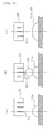
- Fig. 1 is an explanatory view showing a recording method according to a first embodiment of the present invention.
- the desired function can be provided by placing an A4-size aluminum plate having a thickness t of 3 mm, serving as a material to be printed, on an A4-size aluminum plate having a thickness t of 5 mm which is heated to 40°C, and performing printing thereon.
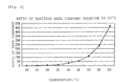
- the heating temperature is set at 30°C to 80°C or 30°C to 60°C, or more preferably, at 40°C to 50°C, in consideration of the decomposition temperature of the pigment-based ink.
- the above-described heating method in which a material to be printed is placed on a heating plate (aluminum plate), may be replaced with, for example, partial heating with a laser, partial heating with infrared rays, heating with light and warm air, or heating with a stroboscope (including a strobe light).
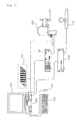
- Fig. 5 is a view showing the configuration of the principal part of a recording apparatus for performing printing shown in Fig. 1(c).
- a robot system controller (hereinafter referred to as a "controller") 100 is structured by an FA personal computer and is connected to a display 101, a keyboard 102, and a mouse 103.
- the controller 100 controls a printing substrate 104, a SCARA robot driver 120, and a multi-axis pulse-motor driver 130, which will be described later.
- the controller 100 also converts bit map data of each color into data in accordance with the nozzle arrangement, and stores the converted data as print data in a file (hereinafter referred to as an "N file").
- the display 101 is a GUI by the controller (FA personal computer) 100, and constitutes a man-machine interface, which performs the following operations, together with the keyboard 102 and the mouse 103.
- the printing substrate 104 is inserted as an optional substrate in the controller (FA personal computer) 100.
- the printing substrate 104 sequentially fetches data for one line from the N file stored in the controller 100, and sends the data to a head driver 110 in response to the operation of a SCARA robot 121 (relative movement between the printer head and the material to be printed).
- the head driver 110 actuates piezoelectric devices corresponding to the ink nozzles in the printer head 111 based on signals sent from the printing substrate 104 so that ink droplets are ejected for printing.
- the SCARA robot driver (four axis) 120 drives the SCARA robot 121 in a four-axis manner based on signals from the controller 100.
- the head driver 110 and the printer head 111 are attached to the SCARA robot 121.
- the printer head 111 is mounted at the leading end of an arm of the SCARA robot 121, and the three-dimensional position thereof is controlled arbitrarily so that the distance between the printer head 111 and the printing position is controlled to be constant.
- the multi-axis pulse-motor driver 130 controls a robot with linear and revolution axes 131 according to signals from the controller 100.
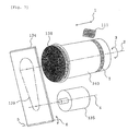
- Fig. 6 is an explanatory view showing an example of a structure of the robot with linear and revolution axes 131.
- a mounting plate 134 is mounted on a substrate 133 so as to stand substantially perpendicularly thereto.
- One side of the mounting plate 134 is provided with a pulse motor 135 for rotational driving and a mounting jig 136 for mounting a solid material to be printed.
- a pulse motor 135 for rotational driving
- a mounting jig 136 for mounting a solid material to be printed.
- description will be given of a case in which printing is performed on, for example, an aluminum can 140 serving as the solid material to be printed, which has been subjected to the treatment shown in Fig. 1(b).
- the mounting jig 136 has a cylindrical outer shape which conforms to the inner surface of the aluminum can 140.
- the other side of the mounting plate 134 is provided with a toothed pulley 137 connected to the pulse motor 135, and a toothed pulley 138 connected to the mounting jig 136. These toothed pulleys 137 and 138 are linked by a timing belt 139.
- the rotational force of the pulse motor 135 is transmitted to the mounting jig 136 via the toothed pulley 137, the timing belt 139, and the toothed pulley 138, thereby rotating the mounting jig 136.
- the mounting plate 134 is mounted on the substrate 133 so that the mounting angle ⁇ with respect to the substrate 133 can be adjusted properly.
- the substrate 133 is supported so as to be linearly moved by driving another pulse motor (not shown).
- the mounting jig 136 is driven rotationally and linearly in this way.
- Fig. 7 is an explanatory view conceptually showing the recording apparatus shown in Fig. 5 in order to explain the operation thereof.
- the printer head 111 is mounted at the leading end of the arm of the SCARA robot 121 and can be moved in a horizontal direction 1 by a position feedback type servo motor (not shown) disposed in the SCARA robot 121.
- the aluminum can 140 is mounted by being fitted on the mounting jig 136.
- the mounting jig 136 is driven by the pulse motor 135 so as to rotate on a center line 2 in a direction of arrow 3.
- the rotation center line 2 of the mounting jig 136 and a rotation center line 4 of the pulse motor 135 are parallel to each other, and are perpendicular to a bearing mechanism (not shown) of the mounting jig 136 and the mounting surface of the mounting plate 135.
- the mounting plate 134 can be fixed so as to pivot on a pivot center line 5 perpendicular to the center line 4 in a direction of arrow 6, as described above (see ⁇ in Fig. 6). While the mounting jig 136 is cylindrical in the example shown in Fig.
- the mounting plate 134 is fixed at an angle so that the horizontal lower surface of the printer head 111 serving as an ink ejecting surface and the printing tangent plane of the (tapered) aluminum can 140 are parallel to each other.
- the pulse motor 135 is continuously rotated, and the mounting jig 136 is also rotated.
- the printer head 111 is moved to the left or right as shown by arrow 1, and ink droplets are ejected in an appropriate timing with the rotation and the movement.
- printing can be performed in a print area 7 on the surface of the aluminum can 140 serving as the solid material to be printed.
- the printed portion is heated by partial heating with a laser, partial heating with infrared rays, heating with light and warm air, or heating with a stroboscope (including a strobe light), thereby speeding up ion binding or molecular adsorption of the ink droplets.
Landscapes
- Ink Jet (AREA)
- Ink Jet Recording Methods And Recording Media Thereof (AREA)
Applications Claiming Priority (2)
| Application Number | Priority Date | Filing Date | Title |
|---|---|---|---|
| JP2000202494 | 2000-07-04 | ||
| JP2000202494A JP2002019260A (ja) | 2000-07-04 | 2000-07-04 | 記録方法 |
Publications (3)
| Publication Number | Publication Date |
|---|---|
| EP1170125A2 true EP1170125A2 (fr) | 2002-01-09 |
| EP1170125A3 EP1170125A3 (fr) | 2002-07-10 |
| EP1170125B1 EP1170125B1 (fr) | 2007-02-14 |
Family
ID=18700014
Family Applications (1)
| Application Number | Title | Priority Date | Filing Date |
|---|---|---|---|
| EP01115640A Expired - Lifetime EP1170125B1 (fr) | 2000-07-04 | 2001-07-03 | Dispositif d'enregistrement |
Country Status (5)
| Country | Link |
|---|---|
| US (3) | US6619793B2 (fr) |
| EP (1) | EP1170125B1 (fr) |
| JP (1) | JP2002019260A (fr) |
| DE (1) | DE60126534T2 (fr) |
| TW (1) | TW592982B (fr) |
Cited By (2)
| Publication number | Priority date | Publication date | Assignee | Title |
|---|---|---|---|---|
| EP1464507A1 (fr) * | 2003-04-04 | 2004-10-06 | ES Technology (Société Anonyme) | Procédé et dispositif de marquage couleur de supports |
| WO2013185814A1 (fr) * | 2012-06-13 | 2013-12-19 | Kronoplus Technical Ag | Panneau présentant une couche décorative et procédé d'impression de plaques |
Families Citing this family (12)
| Publication number | Priority date | Publication date | Assignee | Title |
|---|---|---|---|---|
| JP2002019260A (ja) * | 2000-07-04 | 2002-01-23 | Seiko Epson Corp | 記録方法 |
| KR100915275B1 (ko) | 2001-11-05 | 2009-09-03 | 가부시키가이샤 히타치세이사쿠쇼 | 무선 통신 시스템 및 그 통신 제어 방법 및 무선 통신기 |
| JP2004337701A (ja) | 2003-05-14 | 2004-12-02 | Seiko Epson Corp | 液滴吐出方法、及び液滴吐出装置 |
| DE10349452A1 (de) * | 2003-10-23 | 2005-05-25 | Bosch Rexroth Ag | Roboter vom Scara-Typ |
| WO2005043326A2 (fr) * | 2003-10-31 | 2005-05-12 | Docomo Communications Laboratories Usa, Inc. | Mecanismes de cryptage et de signature utilisant des mises en correspondance de messages afin de reduire la taille desdits messages |
| JP2007276853A (ja) * | 2006-04-10 | 2007-10-25 | Katsushika:Kk | 化粧品容器及び容器の染色方法。 |
| JP4367481B2 (ja) * | 2006-11-29 | 2009-11-18 | セイコーエプソン株式会社 | パターン形成方法 |
| US8197055B2 (en) * | 2006-11-29 | 2012-06-12 | Seiko Epson Corporation | Patterning method, droplet discharging device and circuit board |
| US20080204535A1 (en) * | 2007-02-22 | 2008-08-28 | Seiko Epson Corporation | Ink jet printer |
| JP5172381B2 (ja) | 2008-02-22 | 2013-03-27 | 日立建機株式会社 | 建設機械 |
| US8366263B2 (en) * | 2008-07-16 | 2013-02-05 | Mantel Digital, Inc. | Ink jet printing method and apparatus for coloring an article of aluminium or aluminium alloys |
| US9815995B2 (en) | 2012-02-03 | 2017-11-14 | Toyo Seikan Group Holdings, Ltd. | Ink for ink-jet printing, printed cylindrical containers and method for producing the same |
Citations (1)
| Publication number | Priority date | Publication date | Assignee | Title |
|---|---|---|---|---|
| JPH11326548A (ja) | 1997-10-28 | 1999-11-26 | Seiko Epson Corp | 時計用文字盤およびその製造方法 |
Family Cites Families (20)
| Publication number | Priority date | Publication date | Assignee | Title |
|---|---|---|---|---|
| JPS6052953B2 (ja) * | 1978-10-03 | 1985-11-22 | 凸版印刷株式会社 | プラスチック成型体への印刷方法 |
| DE3115532A1 (de) * | 1980-04-17 | 1982-01-28 | Canon K.K., Tokyo | Tintenstrahl-aufzeichnungsverfahren und aufzeichnungstinte fuer die aufzeichnung auf einem bildempfangsmaterial |
| JPS61163296A (ja) | 1985-01-11 | 1986-07-23 | Seiko Epson Corp | 多色時計ケ−スの製造方法 |
| EP0218956A1 (fr) * | 1985-09-24 | 1987-04-22 | Asahi Glass Company Ltd. | Feuille d'enregistrement |
| US5130726A (en) * | 1989-02-28 | 1992-07-14 | Canon Kabushiki Kaisha | Ink jet recording apparatus |
| JP3215977B2 (ja) | 1989-11-06 | 2001-10-09 | コロナ工業株式会社 | 陽極酸化皮膜を利用したアルミニウム上への電子複写法 |
| JPH03244545A (ja) | 1990-02-23 | 1991-10-31 | Canon Inc | ファクシミリ装置 |
| US5145518A (en) * | 1990-06-27 | 1992-09-08 | Xerox Corporation | Inks containing block copolymer micelles |
| CA2131424C (fr) * | 1993-09-30 | 2000-01-18 | Masami Ikeda | Methode de production d'images, procede de production de plaques d'aluminium decoratives, appareil utilisant ce procede, plaques d'aluminium decoratives et support d'enregistrement connexe |
| JPH08156394A (ja) | 1994-12-02 | 1996-06-18 | Canon Inc | 画像形成方法、装飾アルミニウム板の製造方法及び製造装置、装飾アルミニウム板 |
| US5771054A (en) * | 1995-05-30 | 1998-06-23 | Xerox Corporation | Heated drum for ink jet printing |
| JPH09314986A (ja) | 1996-05-28 | 1997-12-09 | Canon Electron Inc | インクジェット記録用アルミニウム板 |
| US5746817A (en) * | 1996-08-16 | 1998-05-05 | Rexam Graphics Inc. | Ink jet ink composition |
| US6068368A (en) | 1997-08-21 | 2000-05-30 | The Trustees Of Princeton University | Method and apparatus for reducing ink spreading on paper in inkjet printing |
| JPH11277724A (ja) * | 1998-03-27 | 1999-10-12 | Seiko Epson Corp | 印刷物品の製造方法および印刷装置 |
| JPH11277725A (ja) | 1998-03-30 | 1999-10-12 | Seiko Epson Corp | 印刷物品の製造方法および印刷装置 |
| JP3147883B2 (ja) | 1999-01-11 | 2001-03-19 | 大日本インキ化学工業株式会社 | 光ディスクの印刷方法 |
| JP2002019260A (ja) * | 2000-07-04 | 2002-01-23 | Seiko Epson Corp | 記録方法 |
| WO2004044058A1 (fr) | 2002-11-11 | 2004-05-27 | Ciba Specialty Chemicals Holding Inc. | Colorants a base de phthalimidyle azo, procede de preparation et utilisation |
| TWI260653B (en) | 2005-12-19 | 2006-08-21 | Tatung Co | Method for connecting low-voltage side inside large current transformer |
-
2000
- 2000-07-04 JP JP2000202494A patent/JP2002019260A/ja not_active Withdrawn
-
2001
- 2001-05-29 TW TW090112939A patent/TW592982B/zh not_active IP Right Cessation
- 2001-07-03 DE DE60126534T patent/DE60126534T2/de not_active Expired - Lifetime
- 2001-07-03 US US09/899,012 patent/US6619793B2/en not_active Expired - Lifetime
- 2001-07-03 EP EP01115640A patent/EP1170125B1/fr not_active Expired - Lifetime
-
2003
- 2003-07-30 US US10/630,183 patent/US6808257B2/en not_active Expired - Lifetime
-
2004
- 2004-09-29 US US10/953,645 patent/US6969167B2/en not_active Expired - Lifetime
Patent Citations (1)
| Publication number | Priority date | Publication date | Assignee | Title |
|---|---|---|---|---|
| JPH11326548A (ja) | 1997-10-28 | 1999-11-26 | Seiko Epson Corp | 時計用文字盤およびその製造方法 |
Cited By (8)
| Publication number | Priority date | Publication date | Assignee | Title |
|---|---|---|---|---|
| EP1464507A1 (fr) * | 2003-04-04 | 2004-10-06 | ES Technology (Société Anonyme) | Procédé et dispositif de marquage couleur de supports |
| FR2853278A1 (fr) * | 2003-04-04 | 2004-10-08 | Es Technology | Procede et dispositif de marquage couleur de supports |
| WO2013185814A1 (fr) * | 2012-06-13 | 2013-12-19 | Kronoplus Technical Ag | Panneau présentant une couche décorative et procédé d'impression de plaques |
| CN104364089A (zh) * | 2012-06-13 | 2015-02-18 | 克诺那普雷斯技术股份公司 | 具有装饰层的板和印制板的方法 |
| EP2891562A1 (fr) * | 2012-06-13 | 2015-07-08 | Kronoplus Technical AG | Panneau avec couche décorative ainsi que procédé d'impression de plaques |
| RU2598308C2 (ru) * | 2012-06-13 | 2016-09-20 | Кроноплюс Техникаль АГ | Способ печати на плитах |
| US9744716B2 (en) | 2012-06-13 | 2017-08-29 | Kronoplus Technical Ag | Panel having decorative layer and method for printing panels |
| US11292182B2 (en) | 2012-06-13 | 2022-04-05 | Xylo Technologies Ag | Panel having decorative layer and method for printing panels |
Also Published As
| Publication number | Publication date |
|---|---|
| US6619793B2 (en) | 2003-09-16 |
| DE60126534T2 (de) | 2007-11-22 |
| US6969167B2 (en) | 2005-11-29 |
| JP2002019260A (ja) | 2002-01-23 |
| US20040021756A1 (en) | 2004-02-05 |
| DE60126534D1 (de) | 2007-03-29 |
| US20050078159A1 (en) | 2005-04-14 |
| EP1170125A3 (fr) | 2002-07-10 |
| TW592982B (en) | 2004-06-21 |
| US6808257B2 (en) | 2004-10-26 |
| EP1170125B1 (fr) | 2007-02-14 |
| US20020018850A1 (en) | 2002-02-14 |
Similar Documents
| Publication | Publication Date | Title |
|---|---|---|
| EP1170125B1 (fr) | Dispositif d'enregistrement | |
| EP1547795B1 (fr) | Procédé et dispositif pour améliorer la qualité d'impression à jet d'encre | |
| US6354700B1 (en) | Two-stage printing process and apparatus for radiant energy cured ink | |
| JP3802616B2 (ja) | インクジェット記録方法 | |
| EP0671268A1 (fr) | Appareil d'enregistrement a jet d'encre | |
| ES2116478T3 (es) | Metodo para la fabricacion de un cabezal para impresion por chorros de tinta. | |
| JPH02502175A (ja) | 高温溶解インクの噴射印字におけるインク滴の拡散の制御 | |
| US20120069073A1 (en) | Fluid ejecting apparatus and image formation method | |
| US6139134A (en) | Printer | |
| JPS61249755A (ja) | 記録装置 | |
| JPH0975825A (ja) | 塗膜形成装置および塗膜形成方法 | |
| JP6296901B2 (ja) | 立体物の製造方法およびその製造装置 | |
| JPS62191157A (ja) | サ−マルインクジエツト方式記録装置 | |
| JPH11277724A (ja) | 印刷物品の製造方法および印刷装置 | |
| JP3045117B2 (ja) | プリンタ装置 | |
| JP2589128B2 (ja) | レーザーマーキング方法 | |
| JP4006987B2 (ja) | カラーマーキング方法およびマーキングされた筐体部品 | |
| JP4401970B2 (ja) | 印刷装置 | |
| JPS5872461A (ja) | インクジエツト記録装置 | |
| JP3297804B2 (ja) | プリンタ装置 | |
| KR20030045221A (ko) | 잉크젯 프린터의 헤드 제조방법 | |
| JPH1134285A (ja) | 印刷装置 | |
| JPH03264362A (ja) | インクジェット記録装置および該装置における記録方法 | |
| CN118322723A (zh) | 一种一色一固化的打印模块排列结构 | |
| EP0255841A1 (fr) | Dispositif d'enregistrement d'images |
Legal Events
| Date | Code | Title | Description |
|---|---|---|---|
| PUAI | Public reference made under article 153(3) epc to a published international application that has entered the european phase |
Free format text: ORIGINAL CODE: 0009012 |
|
| AK | Designated contracting states |
Kind code of ref document: A2 Designated state(s): AT BE CH CY DE DK ES FI FR GB GR IE IT LI LU MC NL PT SE TR |
|
| AX | Request for extension of the european patent |
Free format text: AL;LT;LV;MK;RO;SI |
|
| PUAL | Search report despatched |
Free format text: ORIGINAL CODE: 0009013 |
|
| AK | Designated contracting states |
Kind code of ref document: A3 Designated state(s): AT BE CH CY DE DK ES FI FR GB GR IE IT LI LU MC NL PT SE TR |
|
| AX | Request for extension of the european patent |
Free format text: AL;LT;LV;MK;RO;SI |
|
| RIC1 | Information provided on ipc code assigned before grant |
Free format text: 7B 41J 2/01 A, 7B 41J 11/00 B |
|
| 17P | Request for examination filed |
Effective date: 20021108 |
|
| AKX | Designation fees paid |
Designated state(s): DE FR GB |
|
| 17Q | First examination report despatched |
Effective date: 20050318 |
|
| GRAP | Despatch of communication of intention to grant a patent |
Free format text: ORIGINAL CODE: EPIDOSNIGR1 |
|
| RAP1 | Party data changed (applicant data changed or rights of an application transferred) |
Owner name: SEIKO EPSON CORPORATION |
|
| GRAS | Grant fee paid |
Free format text: ORIGINAL CODE: EPIDOSNIGR3 |
|
| GRAA | (expected) grant |
Free format text: ORIGINAL CODE: 0009210 |
|
| AK | Designated contracting states |
Kind code of ref document: B1 Designated state(s): DE FR GB |
|
| REG | Reference to a national code |
Ref country code: GB Ref legal event code: FG4D |
|
| REF | Corresponds to: |
Ref document number: 60126534 Country of ref document: DE Date of ref document: 20070329 Kind code of ref document: P |
|
| ET | Fr: translation filed | ||
| PLBE | No opposition filed within time limit |
Free format text: ORIGINAL CODE: 0009261 |
|
| STAA | Information on the status of an ep patent application or granted ep patent |
Free format text: STATUS: NO OPPOSITION FILED WITHIN TIME LIMIT |
|
| 26N | No opposition filed |
Effective date: 20071115 |
|
| REG | Reference to a national code |
Ref country code: FR Ref legal event code: PLFP Year of fee payment: 16 |
|
| REG | Reference to a national code |
Ref country code: FR Ref legal event code: PLFP Year of fee payment: 17 |
|
| PGFP | Annual fee paid to national office [announced via postgrant information from national office to epo] |
Ref country code: GB Payment date: 20170628 Year of fee payment: 17 Ref country code: FR Payment date: 20170613 Year of fee payment: 17 |
|
| PGFP | Annual fee paid to national office [announced via postgrant information from national office to epo] |
Ref country code: DE Payment date: 20170627 Year of fee payment: 17 |
|
| REG | Reference to a national code |
Ref country code: DE Ref legal event code: R119 Ref document number: 60126534 Country of ref document: DE |
|
| GBPC | Gb: european patent ceased through non-payment of renewal fee |
Effective date: 20180703 |
|
| PG25 | Lapsed in a contracting state [announced via postgrant information from national office to epo] |
Ref country code: GB Free format text: LAPSE BECAUSE OF NON-PAYMENT OF DUE FEES Effective date: 20180703 Ref country code: FR Free format text: LAPSE BECAUSE OF NON-PAYMENT OF DUE FEES Effective date: 20180731 Ref country code: DE Free format text: LAPSE BECAUSE OF NON-PAYMENT OF DUE FEES Effective date: 20190201 |