EP1170929A2 - Klappbares und tragbares Funkgerät - Google Patents
Klappbares und tragbares Funkgerät Download PDFInfo
- Publication number
- EP1170929A2 EP1170929A2 EP01116354A EP01116354A EP1170929A2 EP 1170929 A2 EP1170929 A2 EP 1170929A2 EP 01116354 A EP01116354 A EP 01116354A EP 01116354 A EP01116354 A EP 01116354A EP 1170929 A2 EP1170929 A2 EP 1170929A2
- Authority
- EP
- European Patent Office
- Prior art keywords
- housing
- radio terminal
- portable radio
- foldable portable
- terminal according
- Prior art date
- Legal status (The legal status is an assumption and is not a legal conclusion. Google has not performed a legal analysis and makes no representation as to the accuracy of the status listed.)
- Granted
Links
- 239000002184 metal Substances 0.000 claims description 40
- 239000012212 insulator Substances 0.000 claims description 18
- 239000004020 conductor Substances 0.000 claims description 17
- 230000005684 electric field Effects 0.000 description 7
- 238000010276 construction Methods 0.000 description 4
- 230000000694 effects Effects 0.000 description 3
- 238000004519 manufacturing process Methods 0.000 description 3
- 238000013461 design Methods 0.000 description 2
- 238000005259 measurement Methods 0.000 description 2
- 238000005096 rolling process Methods 0.000 description 2
- 206010067482 No adverse event Diseases 0.000 description 1
- 230000015556 catabolic process Effects 0.000 description 1
- 230000008859 change Effects 0.000 description 1
- 238000006731 degradation reaction Methods 0.000 description 1
- 238000011161 development Methods 0.000 description 1
- 238000005516 engineering process Methods 0.000 description 1
- 230000006872 improvement Effects 0.000 description 1
- 239000000463 material Substances 0.000 description 1
- 238000010295 mobile communication Methods 0.000 description 1
- 230000010355 oscillation Effects 0.000 description 1
- 238000012545 processing Methods 0.000 description 1
- 230000009467 reduction Effects 0.000 description 1
- 230000002441 reversible effect Effects 0.000 description 1
- 238000003892 spreading Methods 0.000 description 1
- 230000000007 visual effect Effects 0.000 description 1
Images








Classifications
-
- H—ELECTRICITY
- H04—ELECTRIC COMMUNICATION TECHNIQUE
- H04B—TRANSMISSION
- H04B1/00—Details of transmission systems, not covered by a single one of groups H04B3/00 - H04B13/00; Details of transmission systems not characterised by the medium used for transmission
- H04B1/38—Transceivers, i.e. devices in which transmitter and receiver form a structural unit and in which at least one part is used for functions of transmitting and receiving
- H04B1/3827—Portable transceivers
- H04B1/3833—Hand-held transceivers
-
- H—ELECTRICITY
- H01—ELECTRIC ELEMENTS
- H01Q—ANTENNAS, i.e. RADIO AERIALS
- H01Q1/00—Details of, or arrangements associated with, antennas
- H01Q1/08—Means for collapsing antennas or parts thereof
- H01Q1/084—Pivotable antennas
-
- H—ELECTRICITY
- H01—ELECTRIC ELEMENTS
- H01Q—ANTENNAS, i.e. RADIO AERIALS
- H01Q1/00—Details of, or arrangements associated with, antennas
- H01Q1/12—Supports; Mounting means
- H01Q1/22—Supports; Mounting means by structural association with other equipment or articles
- H01Q1/24—Supports; Mounting means by structural association with other equipment or articles with receiving set
- H01Q1/241—Supports; Mounting means by structural association with other equipment or articles with receiving set used in mobile communications, e.g. GSM
- H01Q1/242—Supports; Mounting means by structural association with other equipment or articles with receiving set used in mobile communications, e.g. GSM specially adapted for hand-held use
-
- H—ELECTRICITY
- H04—ELECTRIC COMMUNICATION TECHNIQUE
- H04M—TELEPHONIC COMMUNICATION
- H04M1/00—Substation equipment, e.g. for use by subscribers
- H04M1/02—Constructional features of telephone sets
- H04M1/0202—Portable telephone sets, e.g. cordless phones, mobile phones or bar type handsets
- H04M1/0206—Portable telephones comprising a plurality of mechanically joined movable body parts, e.g. hinged housings
- H04M1/0208—Portable telephones comprising a plurality of mechanically joined movable body parts, e.g. hinged housings characterized by the relative motions of the body parts
- H04M1/0214—Foldable telephones, i.e. with body parts pivoting to an open position around an axis parallel to the plane they define in closed position
- H04M1/0216—Foldable in one direction, i.e. using a one degree of freedom hinge
Definitions
- This invention relates to a foldable portable radio terminal with a hinge. More specifically, this invention relates to a foldable portable radio terminal whose lower housing being provided with an antenna.
- portable terminals have come into wide use with the advancement of technology in the field mobile communications. Under such circumstances, in order to meet various demands of users, manufacturers or vendors of a portable terminal have brought a great variety of portable terminals to the market. In particular, recent technological development has enabled a portable terminal to access the Internet or the like, which has then given rise to a user's strong request for a portable terminal with a large-sized display.
- a foldable portable radio terminal configured by separate housings, an upper housing and a lower housing, where these two housings are connected via a hinge.
- Such kind of foldable portable radio terminal has enjoyed great popularity since it sufficiently meets demands of users, being provided with the following features.
- an operating unit and a display have respectively a large area on the terminal.
- the operating unit functions as an interface with a user, and the display provides a user with information by displaying characters or the like on the display.
- the portable terminal when the portable terminal is not in use, it can be folded, thus occupying as little space as possible.
- the portable terminal may be designed so that spacing between a microphone and a receiver will be equal to that between an ear and a mouth of a user when the terminal is unfolded for use.
- the terminal with this spacing provides a user with a high telephone speech quality.
- a prior art foldable portable radio terminal comprises an upper housing 101 and a lower housing 102.
- the upper housing 101 includes an upper-housing front panel 103 and an upper-housing rear panel 104.
- the lower housing 102 includes a lower-housing front panel 105 and a lower-housing rear panel 106.
- an upper-housing circuit 108 In a vessel formed in the upper housing 101 by the upper-housing front panel 103 and the upper-housing rear panel 104, there are contained an upper-housing circuit 108, a control unit 110, a receiver 114 and a display 118. In addition, an antenna 112 and a feeding conductor 113 for supplying power to the antenna 112 are contained in the vessel.
- a vessel in the lower housing 102 formed by the lower-housing front panel 105 and the lower-housing rear panel 106, there are contained a battery 107, a lower-housing circuit 109, a radio unit 111 and a key operating unit 115.
- the upper housing 101 and the lower housing 102 are connected via a hinge 117, around which these two housings can be revolved or rotated. With this construction, the portable terminal can be folded as well as unfolded by a user.
- the antenna 112 provided within the upper housing 101 is connected to the radio unit 111 via a coaxial cable 119.
- the power supplied to the upper-housing circuit 108 from the battery 107 is fed to the antenna 112 through the feeding conductor 113.
- the battery 107 is included in the lower housing 102 in consideration of weight balance when the terminal is held by a user, and of stability when it is put on the desk. Furthermore, the radio unit 111 including a transmitter which consumes a large current is located in the lower housing 102, since the radio unit is desirable to be located adjacently to the battery 107 in order to reduce a voltage drop caused by each printed circuit pattern connected to the power source. It is also preferable that the radio unit 111 is included in the lower housing 102 so as to provide a thinner foldable portable radio terminal.
- the upper-housing circuit 108 and the lower-housing circuit 109 are electrically connected by a connection unit 116 having plural pairs of conductors, thus transmitting/receiving signals through the connection unit 116.
- the battery 107 is connected to the lower-housing circuit 109, thus supplying power to each unit through the lower-housing circuit 109.
- connection unit 116 is composed of a flexible printed wiring board (i.e., a flexible board) in order to prevent damage to a conductor when the housing moves or rotates around the hinge 117. Additionally, the upper-housing front panel 103 and the lower-housing front panel 105 according to the conventional foldable portable radio terminal are made of metal so as to secure its strength.
- the antenna 112 is placed at the upper part of the upper-housing rear panel 104 and being made contact with the feeding conductor 113 arranged in the upper-housing circuit 108. As shown in Fig. 1, the feeding conductor 113 receives power from the battery 107 through the upper-housing circuit 108, the connection unit 116 and the lower-housing circuit 109.
- the coaxial cable 119 which provides connection between the radio unit 111 and the antenna 112 is fixed at a designated place with a cable clamp (not shown).
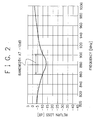
- Fig. 2 shows return loss characteristics of the conventional foldable portable radio terminal with the above-mentioned structure when the antenna 112 is extended.
- a return loss mentioned in the present invention is a comparison result between two current levels, a level originally inputted into the antenna and a level reflected therefrom. More specifically, the return loss indicates a ratio of a signal sent from the radio unit to the antenna (that is, a signal sent from an impedance matching circuit located between the radio unit and the antenna, to the antenna), to a signal reflected from the antenna.
- the upper-housing circuit 108 and the lower-housing circuit 109 respectively have the size of approx. 75mm x 40mm, the upper housing 101 and the lower housing 102 are approx. 90mm x 45mm, and the spacing between the upper-housing circuit 108 and the lower-housing circuit 109 is approx. 15mm.
- the antenna 112 has a helical antenna inside its casing.
- the helical antenna has the following measurement; approx. 6 mm in diameter and approx. 15mm in height.
- the helical antenna provides an impedance matching with a feeding line using an impedance matching circuit (not shown) provided between the feeding conductor 113 and the radio unit 111.
- the first conventional foldable portable radio terminal has a bandwidth of approx. 40MHz when a return loss is -10dB.
- the first conventional terminal shown in Fig. 1 has a structural problem that the coaxial cable 119 is required in order to make an electrical connection between the antenna 112 and the radio unit 111. This leads to an inadequate assembling efficiency in a manufacturing process, compared with efficiency in assembling a no-foldable type portable radio terminal.
- a second conventional foldable portable radio terminal is provided with structure where an antenna 112 is located in a lower housing as shown in Fig. 3.
- the antenna 112 and a feeding conductor 113 are included in a lower housing 102, thus eliminating the above-mentioned coaxial cable 119 connecting the antenna 112 and a radio unit 111.
- the remaining structures of the second conventional terminal are the same as those of the first terminal shown in Fig. 1.
- the positioning of the antenna in the lower housing 102 has changed the impedance with respect to a circuit, therefore an impedance matching circuit provided between the antenna 112 and the radio unit 111 requires readjustment.
- Fig. 4 shows return loss characteristics when the antenna 112 is positioned in the lower housing 102.
- the second conventional foldable portable radio terminal uses the same antenna 112 (including a helical antenna) as that of the first conventional terminal which has been used for measuring return loss characteristics shown in Fig. 2.
- the second conventional terminal has a problem that the bandwidth at which the antenna can transmit/receive signals becomes extremely narrow. This problem is obvious from the following comparison.
- a bandwidth at that loss is approx. 40MHz as shown in Fig. 2, however, it is approx. 30MHz as shown in Fig. 4.
- a foldable portable radio terminal with an antenna arranged in the lower housing, whereby eliminating a coaxial cable conventionally used for connecting the antenna and a radio unit and improving antenna characteristics.
- a foldable portable radio terminal having a first housing for including a first circuit unit inside and a second housing for including a second circuit unit inside, said first and second housings are connected through the intermediary of a hinge so as to rotate around said hinge, said terminal comprising: power-supply means for supplying power to said first and second circuit units; and connecting means for electrically connecting said first and second circuit units, wherein said connecting means having a prescribed shape and length, so that said connecting means generates an inductance which serves as a load to a high-frequency current.
- the connecting means according to the foldable portable radio terminal of the present invention is a flexible board having conductors for generating said inductance.
- Prescribed shape is a shape where said connecting means partially has a spiral structure with one or more of turns, and said prescribed length is a length capable of connecting said first and second circuit units with said spiral structure being maintained.
- said connecting means when it is expanded, is S-shaped including first, second and third zonal areas, said first zonal area corresponding to one end portion of said connecting means and being connected to said first circuit unit, said second zonal area corresponding to another end portion of said connecting means and being connected to said second circuit unit, and said third zonal area corresponding to an area which lies intermediary of said first and second zonal areas, and wherein said third zonal area being associated with a portion where said spiral structure is formed and having a length for avoiding interconnection between said first and second zonal areas when said spiral structure is being maintained.
- said connecting means is arranged to go through said hinge, and is housed inside said hinge at a portion where said spiral structure is formed.
- the connecting means when it is expanded, is tuning-fork shaped including first, second and third zonal areas, said first zonal area corresponding to one end portion of one prong and being connected to said first circuit unit, said second zonal area corresponding to another end portion of another prong and being connected to said first circuit unit, and said third zonal area corresponding to an end portion of a stem and being connected to said second circuit unit, wherein a portion where said prongs and stem merge and its vicinity is rolled up to form said coil structure, and wherein said first, second and third zonal areas are arranged apart for avoiding interconnection when said coil structure is being maintained.
- the connecting means when it is expanded, has a shape including first, second and third zonal areas, said first zonal area corresponding to one end portion of said connecting means and being connected to said first circuit unit, said second zonal area corresponding to another end portion of said connecting means and being connected to said second circuit unit, and said third zonal area corresponding to a portion which lies intermediary of said first and second zonal areas and takes a crank shape.
- the antenna unit and radio unit are connected to said second circuit unit within said second housing, and said first circuit unit has a length of approximately half of said second circuit unit.
- the first housing is made of metal and said second housing is made of insulator, and said first housing is electrically connected to said first circuit unit.
- the first housing comprising a front panel and a rear panel has configurations either where said front panel being made of metal and said rear panel being made of insulator or where said front panel being made of insulator and said rear panel being made of metal, said panels made of metal being electrically connected to said first circuit unit.
- the first housing is made of insulator and said second housing is made of metal, and said second housing is electrically connected to said second circuit unit.
- the second housing comprising a front panel and a rear panel has configurations either where said front panel being made of metal and said rear panel being made of insulator or where said front panel being made of insulator and said rear panel being made of metal, said panels made of metal being electrically connected to said second circuit unit.
- a foldable portable radio terminal of the present invention is characterized by comprising an upper housing and a lower housing.
- the lower housing is provided with at least a battery and a radio unit, and the upper housing has an arbitrary circuit inside. More specifically, an antenna is included in the lower housing, and a wiring length associated with a connection unit connecting an upper-housing circuit and a lower-housing circuit is longer than a distance or spacing between the upper-housing circuit and the lower-housing circuit.
- the foldable portable radio terminal of the present invention since a wiring length of a connection unit is longer than the spacing between the upper-housing circuit and the lower-housing circuit, it is therefore possible to alleviate degradation in antenna characteristics, which is caused by conducting parts in an upper-housing circuit or the like.
- the alleviation is accomplished by arranging the impedance between the upper-housing circuit and the lower-housing circuit, for reducing quantity of current oscillating between the upper housing and the lower housing.
- a part of or the whole of an upper housing and a lower housing is selectively made of metal (diecast) or mold (insulator). If the entire terminal is made of mold, the housing causes no effect on an antenna and preferable antenna characteristics can be realized. However, taking into consideration the strength of the entire terminal, it is desirable to construct the housing with metal.
- both an upper housing and a lower housing are made of metal and connected each other through the intermediary of a hinge, a current generated in the metal oscillates between the housing and a circuit in the housing through the hinge.
- the oscillating current has not necessarily the same phase as that generated in an antenna, and in most cases, the oscillating current acts to degrade antenna characteristics.
- the terminal has a structure where the upper housing is not electrically connected to the lower housing when the foldable portable radio terminal is unfolded.
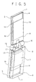
- Fig. 5 is an oblique perspective view showing a structure of a foldable portable radio terminal according to a first embodiment of the present invention.
- the foldable portable radio terminal comprises an upper housing 1 and a lower housing 2, which are connected each other via a hinge 17.
- the upper housing 1 comprises an upper-housing front panel 3 and an upper-housing rear panel 4. Within a vessel constructed by the upper-housing front panel 3 and the rear panel 4, there are provided an upper-housing circuit 8, a controller 10, a receiver 14 and a display unit 18.
- the lower housing 2 comprises a lower-housing front panel 5 and a lower-housing rear panel 6.
- a battery 7 Within a vessel constructed by the lower-housing front panel 5 and the lower-housing rear panel 6, there are provided a battery 7, a lower-housing circuit 9, a radio unit 11, a feeding conductor 13 and a key operating unit 15.
- the lower housing 2 is provided with an antenna 12 proximity to the hinge 17 which is provided between the upper housing 1 and the lower housing 2.
- the hinge 17 is a joint for connecting the upper housing 1 and the lower housing 2, and makes the upper housing 1 and the lower housing 2 rotate around its central axis.
- the antenna 12 located proximity to the hinge 17 is provided in the lower housing 2 on an upper-housing side.
- the antenna 12 is connected to the radio unit 11 through the feeding conductor 13.
- an antenna is provided in an upper housing and connected to a radio unit through a coaxial cable.
- the foldable portable radio terminal of the first embodiment requires no coaxial cable for connecting the radio unit 11 and the antenna 12.
- the antenna 12 is not directly connected to the battery 7, but connected to the battery via the feeding conductor 13, an impedance matching circuit (not shown) and the lower-housing circuit 9.
- the impedance matching circuit is provided for preventing reflection of signals between the antenna 12 and the radio unit 11.
- the circuit equalizes the input impedance looking at the antenna 12 with the output impedance of the radio unit 11 including the impedance matching circuit.
- the radio unit 11 and the battery 7 are included in the lower housing 2, a wire length for connecting the battery 7 and the radio unit 11 may therefore be shorter than that of the conventional one.
- the battery 7 supplies power to the lower-housing circuit 9, and power is supplied to each circuit through the circuit 9.
- the radio unit 11 included in the lower housing 2 comprises circuits necessary for transmitting/receiving signals.
- the radio unit 11 executes as required a processing such as a spectrum-spreading modulation for information to be transmitted.
- the key operating unit 15, exposed on the surface of the lower housing 2 and projecting from the lower-housing front panel 5, serves as an interface between a user and the controller 10.
- the controller 10 included in the upper housing 1 controls each circuit included in the upper housing 1 and the lower housing 2.
- the receiver 14 functions as a voice input/output interface for a user.
- the display unit 18 is exposed on the surface of the upper housing 1 by projecting from the upper-housing front panel 3, and provides a user with a variety of visual information.
- the controller 10, the receiver 14 and the display unit 18 receive power through the upper-housing circuit 8.
- connection unit 16 is a flexible printed wiring board, so that it changes its shape according to rotation of the housings around the hinge 17 (that is, when folding or unfolding the foldable portable radio terminal).
- the connection unit 16 thus acts to maintain connection between the upper-housing circuit 8 and the lower-housing circuit 9.
- connection unit
- connection unit 16 in order to prevent generation of an opposing current which acts as an obstacle to an antenna current, the connection unit 16 functions as a load to the opposing current.
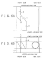
- Figs. 6A and 6B show a structure of the connection unit 16 according to the present embodiment.
- the connection unit 16 is an S-shaped flat cable with a plurality of conductors.
- the connection unit 16 is provided with two zonal areas A and B.
- the area A is for connection to the upper-housing circuit 8, and the area B to the lower-housing circuit 9.
- connection unit 16 There is also provided a zonal area C in the central part of the connection unit 16, which is oblique to a line connecting between the upper-housing circuit 8 and the lower-housing circuit 9, so that the areas A and B keep in parallel each other when the connection unit 16 is rolled up as shown in Fig. 6B.
- connection unit 16 is incorporated into the foldable portable radio terminal in a shape as shown in Fig. 6B.
- the connection unit 16, which is a flexible printed wiring board, is so configured that any part of the board does not contact each other when it is rolled up to have a spiral portion as shown in Fig. 6B. This is because there is a possibility that the flexible printed wiring board can be damaged if portions including its sides contact with each other when the connection unit 16 is moved in accordance with folding or unfolding of the radio terminal. For that reason, the connection unit 16 is constructed in such a way that the areas A and B do not overlap each other.
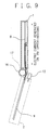
- Fig. 7 is a perspective side view of the foldable portable radio terminal where the upper-housing circuit 8 and the lower-housing circuit 9 are connected via the hinge 17 which includes the connection unit 16 inside.
- Fig. 8 is an enlarged side view of the connection unit 16.
- L1 is a length of the upper-housing circuit 8, L2, of the lower-housing circuit 9 and G, the spacing between the upper-housing circuit 8 and the lower-housing circuit 9.
- the connection unit 16 has a total length of Ls as indicated by a curved line with arrows on both ends, when, for example, the foldable portable radio terminal is unfolded. From Fig. 7 and Fig. 8, it is understood that the length Ls is longer than the spacing G, which is realized by partially rolling up the connection unit 16 in spiral inside the hinge 17.
- Fig. 9 visually shows a current generated in the upper housing 1, which flows into the lower-housing circuit 9 through the connection unit 16.
- the upper-housing rear panel 4 of the upper housing 1 is electrically connected to the upper-housing circuit 8 at the point A.
- High-frequency current generated in the upper housing 1 flows into a ground plane (earth) of the upper-housing circuit 8 through the point A as indicated by a bold line.
- the upper housing 1 is made of metal and exposed to an electromagnetic wave coming from the external of the housing, a high-frequency current is generated in the housing.
- the current thus generated flows in an arbitrary direction, however, for the clarity of the explanation, only a current flowing in the direction from the center of the upper housing 1 to the center of the lower housing 2 will be explained.
- Figs. 10A and 10B respectively show a side view and a top view of the connection unit 16
- Figs. 10C and 10D are a side view and a top view of the antenna 12, respectively.
- These figures show a current and an electric field generated in the connection unit and the antenna, which is caused by an incoming electromagnetic wave.
- Electromagnetic wave coming to the foldable portable radio terminal has an arbitrary phase, therefore a high-frequency current generated in the upper housing 1 (that is, the upper-housing rear panel 4) also has an arbitrary phase.
- the phase is not necessarily the same as that of an electromagnetic wave transmitted from and received by the antenna 12.
- an electric field generated according to the high-frequency current in the upper housing 1 impedes a current generation in the antenna 12. This degrades characteristics (performance) of the antenna.
- Such operation can be seen not only in the antenna 12 including a helical antenna 12-1 as shown in Figs. 10C and 10D but in an antenna with a different structure.
- connection unit 16 is configured to act as an inductance by making the length (Ls) of the connection unit 16 longer than the spacing (G) between the upper-housing circuit 8 and the lower-housing circuit 9.
- the connection unit 16 serves as a load impedance to a high-frequency current oscillating between the upper housing 1 and the lower-housing circuit 9 (or between the lower housing 2 and the upper-housing circuit 8).
- the impedance is further increased by rolling up the connection unit 16 in spiral when the unit is incorporated inside the hinge 17 so that it serves as a coil.
- an electric field set up by a current flowing between the housing (the upper housing 1 and/or the lower housing 2) and the circuit (the upper-housing circuit 8 and/or the lower-housing circuit 9) becomes less effective to the antenna 12.
- This enables the antenna to have a broader bandwidth, over which the antenna can transmit/receive signals. It is understood reduction in current, which flows between the housing and the circuit and prevents generation of current in the antenna by an incoming electromagnetic wave, is caused by the connection unit 16 which is partially in spiral and with the length of Ls.
- a load impedance obtained by arranging a coil-shaped connection unit 16 between the housing and the circuit reduces a high-frequency current which oscillates between the upper housing 1 and the lower-housing circuit 9 (or between the lower housing 2 and the upper-housing circuit 8). It is also obvious that an electric field coming into the antenna 12 deteriorates or degrades characteristics of the antenna 12. Relationships between the spacing G, the length Ls of the connection unit 16 and the antenna characteristics (a return loss) will be explained in detail below with reference to a chart.
- a part or the entire of the housing is made of metal (diecast). That is, any one of the upper-housing front panel 3, the upper-housing rear panel 4, the lower-housing front panel 5 and the lower-housing rear panel 6 is made of metal. If the upper housing 1 and the lower housing 2 are made of a conductive material (for example, metal or diecast), and if the upper housing 1 and the lower housing 2 contact each other when the foldable portable radio terminal is unfolded, oscillation of a current begins through the contact point(s). This means a coil-shaped connection unit 16 fails to produce satisfactory effect. Therefore, it is necessary for the upper housing 1 and the lower housing 2 of the foldable portable radio terminal not to contact electrically each other, provided that the upper housing 1 and the lower housing 2 are made of a conductive material.
- insulator (mold) for either the upper housing 1 or the second housing 2.
- mold is inferior to metal in terms of durability, therefore mold is not suitable for an external wall of the terminal. Considering durability, it becomes necessary to construct part of the housing with a durable metal. It goes without saying that any combination of materials including metal and insulator is to be applied to the present invention without departing from the spirit of the invention.
- the foldable portable radio terminal according to the present embodiment has the radio unit 11 and the antenna 12 in the same housing (the lower housing 2).
- This construction eliminates a coaxial cable required for connecting the radio unit and the antenna in the conventional terminal and increases efficiency with respect to assembling in the production line.
- a high-frequency current generated between housing and circuit is reduced, which makes it possible to avoid generation of an electric field that deteriorates antenna characteristics of the antenna 12.
- the foldable portable radio terminal can transmit/receive signals over a broad bandwidth.
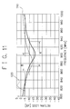
- Fig. 11 is a chart showing antenna characteristics obtained by measuring a foldable portable radio terminal according to the first embodiment of the present invention. Physical dimensions of the foldable portable radio terminal used for the measurement are as follows.
- the upper-housing circuit 8 is approx. 75mm (L1 of Fig. 7) x 40mm
- the lower circuit 9 is approx. 75mm (L2 of Fig. 7) x 40mm.
- Metallic part in the lower housing 2 is approx. 90mm x 45mm, and a spacing (G) between the upper-housing circuit 8 and the lower-housing circuit 9 is approx. 15mm.
- the lower-housing front panel 5 is made of metal and the remaining portions are made of mold, where the lower-housing circuit 9 is grounded at four points.
- the connection unit 16 has a length (Ls) of approx. 40mm. The unit is rolled up to be in partially spiral with one turn, which is included in the hinge 17.
- Fig. 11 shows antenna characteristics, especially return loss characteristics of a foldable portable radio terminal with the above-mentioned structure. Return loss characteristics are obtained by measuring the degree of an electric power reflected from the antenna 12 to the radio unit 11 when the power is inputted into the antenna 12. If return loss characteristics show a good result, it indicates that the electric power inputted from the radio unit 11 to the antenna 12 is outputted from the antenna 12 as a radio wave without any reflection.
- the abscissa indicates a frequency band wherein scanning is executed for the antenna 12.
- the ordinate indicates ratio of signals reflected from the antenna 12 (a return loss in dB).
- a solid line 110 of Fig. 11 shows return loss characteristics of the terminal according to the first embodiment of the present invention, while a chain double-dashed line 120 shows characteristics according to the conventional terminal. Comparing the two curves, the return loss characteristics of the present invention show a desirable value over a wide frequency range as indicated by a range A in Fig. 11, where the characteristics have a peak of loss at the center of the frequency band. This means that the foldable portable radio terminal according to the present invention has antenna characteristics which are less deteriorated and have a broader bandwidth, compared with conventional characteristics as indicated by a range B in the chart.
- the following advantages are obtained. Firstly, miniaturization in structure and improvement in an assembling efficiency are realized, since a coaxial cable becomes unnecessary for connecting a radio unit and an antenna.
- connection unit is longer than a spacing between an upper-housing circuit and a lower-housing circuit, and the connection unit is in spiral inside a hinge.
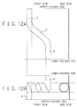
- FIGs. 12A and 12B show a connection unit as a second example.
- the connection unit 16 according to a first example shown in Figs. 6A and 6B is partially in spiral with one turn, the second example is partially in spiral with two turns as shown in Fig. 12B.
- the connection unit 16 as a second example which is a flexible printed wiring board, is constructed so that any part of the unit does not contact each other in the same way as the first example.
- a length of the connection unit 16 according to a second example may be designed to be longer than that of the first example.
- the connection unit 16 according to a second example may also serve as a coil, which increases a load impedance to a high-frequency current. Thus, an electric current which degrades antenna characteristics is to be reduced.
- connection unit has one turn or two turns in spiral, however, the number of turns is not limited to those described here.
- connection unit is Y-shaped or tuning-fork shaped when it is expanded as shown in Fig. 13A.
- the connection unit is a flexible printed wiring board, and configured that any part of the board does not contact each other when it is rolled up to have a ring portion as shown in Fig. 13B.
- connection unit according to a third example has three zonal areas, A, B and C, one of which is corresponding to one end portion of one prong, another one is corresponding to another end portion of another prong, and the last one is corresponding to an end portion of a stem.
- this connection unit is physically more stable than that according to the second example with two turns of spiral rings for the reasons below.
- the connection unit according to the second example has two zonal areas A and B, one of which is to be connected to the upper-housing circuit 8 and another one to the lower-housing circuit 9, which are widely apart each other from a line segment as an axis that is formed by combining the upper-housing circuit 8 and the lower-housing circuit 9.
- only one side of the spiral ring is suspended via a zonal area which is connected to one of the circuits, it is therefore difficult to design and assemble a spiral part which exhibits stability and repeatability.
- a connection unit has zonal areas, A and B, to be connected to the upper-housing circuit 8 and an area C, to the lower-housing circuit 9, which are close each other from a line segment as an axis formed by connecting the upper-housing circuit 8 and the lower-housing circuit 9. Additionally, since both sides and middle of a ring-shaped part are fixed to the zonal areas to be connected to each circuit, it becomes easier to design and assemble a ring-shaped part with physical stability and repeatability.
- connection sides of the connection unit according to a third example are reversible or interchangeable, that is, any side can go to the upper-housing circuit 8 or lower-housing circuit 9.
- connection unit which is Y-shaped the unit may have a plurality of v-shaped parts such as a W-shaped structure.
- connection unit which is obtained by modifying the third example, will be explained in detail by referring to an accompanying drawing.
- connection unit according to the third example has a wiring for connecting the upper-housing circuit 8 and the lower-housing circuit 9, which is shorter in length than that of the connection unit according to the first example. Load impedance arranged between circuits is therefore not increased.
- a connection unit according to the fourth example provides a unit whose length (Ls) is longer than that according to the first example.
- the fourth example provides a unit having a ring-shaped portion with physical stability and repeatability.
- connection unit 16 is constructed so that the unit is to be fixed to the upper-housing circuit 8 at two points, and to the lower-housing circuit 9 at two points.
- connection unit is connected to the upper-housing circuit 8 and the lower-housing circuit 9 in an alternate fashion by four zonal areas.
- the connection unit is formed to have a ring-shaped part, which provides stability and repeatability and further makes a length of the connection unit substantially longer.
- connection unit according to the fourth example has two points (two areas A and C) for connecting to the upper-housing circuit 8 and two points (areas B and D) for connecting to the lower-housing circuit 9. It is also possible that the connection unit has more than two points or areas for the connection to each circuit. In this case, it is necessary that areas of the connection unit to be connected to the circuit should be positioned alternately, and any part of the connection unit should avoid contact each other and with other parts of the terminal.
- the area A of the connection unit is concerned in the electrical connection to the upper-housing circuit 8, and the area D, to the lower-housing circuit 9.
- Another configuration is also possible where the connection unit is electrically connected to the upper-housing circuit 8 and the lower-housing circuit 9 through a plurality of areas, say, combination of areas A, B, C and D.
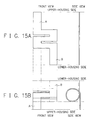
- connection unit according to a fifth example will be described in detail with reference to Fig. 15A.
- the connection unit according to a fifth example is constructed to have crank-shaped portions in its central part, which reside inside the hinge 17.
- the crank-shaped portions may take different forms when the upper housing 1 and the lower housing 2 are moved around the hinge 17. Accordingly, the force applied to the connection unit is dispersed, thus preventing the connection unit from being damaged.
- connection unit may be partially rolled up where there are the crank-shaped portions, as shown in Fig. 15B, to have a ring portion.
- This is a sixth example of a connection unit. It is therefore understood that the ring portion of the connection unit according to a sixth example serves as a coil, which provides a load impedance between the upper-housing circuit 8 and the lower-housing circuit 9, larger than that provided by the connection unit according to a fifth example (see Fig. 15A).
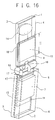
- Fig. 16 shows a foldable portable radio terminal according to a second embodiment, where the length (L1) of the upper-housing circuit 8 is shorter than that of the terminal according to the first embodiment as shown in Fig. 7.
- the foldable portable radio terminal according to the present embodiment is constructed so that the length (L1) of the upper-housing circuit 8 is approximately half of the length (L2) of the lower-housing circuit 9 as shown in Fig. 16. Furthermore, the whole of the upper housing 1 is made of mold, while the remaining parts are constructed in the same way as the first embodiment. This comes from the reason that the upper housing 1 and the upper-housing circuit 8 are required to be electrically connected each other, and therefore a change in the length of the upper-housing circuit 8 has no effects.
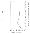
- Fig. 17 is a chart showing relationships between the length (L1) of the upper-housing circuit 8 and a bandwidth over which an antenna can transmit and/or receive signals.
- the foldable portable radio terminal according to a second embodiment has the same dimensions as those of the first embodiment, excepting the length (L1) of the upper-housing circuit 8. That is, the upper-housing circuit 8 is approx. 75mm (L1 of Fig. 2) x 40mm, and the lower circuit 9 is approx. 75mm (L2 of Fig. 2) x 40mm. Metallic part of the lower housing 2 is approx. 90mm x 45mm, and the spacing (G) between the upper-housing circuit 8 and the lower-housing circuit 9 is approx. 15mm.
- the foldable portable radio terminal whose upper housing 1 is made of mold shows satisfactory characteristics with respect to performance of the antenna 12 and a broader bandwidth over which the antenna can transmit and/or receive signals, when the upper-housing circuit 8 has the length (L1) of somewhere between 15mm and 35mm. (If the upper-housing circuit 8 has the length of 35mm, it indicates that the circuit 8 is approx. half the length of the lower-housing circuit 9.) Therefore, the upper-housing circuit 8 of the foldable portable radio terminal according to the second embodiment is set to have the length (L1) of somewhere between 15mm and 35mm.
- the upper-housing circuit 8 When the upper-housing circuit 8 is connected to the receiver 14 as shown in Fig. 16, a high-frequency current flows through a connection wiring from the upper-housing circuit 8 to the receiver 14. In this configuration, the length of the upper-housing circuit 8 is apparently equivalent to the length of the upper-housing circuit 8 together with the length of the receiver 14. Therefore, there is a possibility that the above-mentioned advantages cannot be obtained.
- an inductance will be loaded between the upper-housing circuit 8 and the receiver 14 when the circuit and receiver are connected.
- a high-frequency current it is possible to separate the upper-housing circuit 8 from the receiver 14.
- This configuration brings about satisfactory antenna characteristics and the like as shown in the chart of Fig. 17. It is noted that structure for loading an inductance is not restricted and will be omitted here.
- a foldable portable radio terminal will be explained, where either the upper-housing front panel 3 of the upper housing 1 or the lower-housing front panel 5 of the lower housing 2 is made of metal (diecast).
- a front portion of the housing (the upper-housing front panel 3 or the lower-housing front panel 5) made of metal, is connected to an earth plain of a circuit provided in the same housing.
- Remaining parts of the housing (the upper-housing rear panel 4, the lower-housing rear panel 6, and either the upper-housing front panel 3 or the lower-housing front panel 5) are made of mold (insulator).
- the terminal according to the third embodiment therefore attains the same advantages as those obtained by the above-mentioned embodiments.
- the terminal according to the third embodiment may also have a configuration where the upper-housing front panel 3 and the lower-housing front panel 5 are made of metal, while the upper-housing rear panel 4 and the lower-housing rear panel 6 are made of mold.
- the upper-housing front panel 3 and the lower-housing front panel 5 are structured to have no contact, that is, no electrical connection each other, when the foldable portable radio terminal is unfolded.
- the upper-housing front panel 3 and the lower-housing front panel 5 are made of metal and no electric contact is produced between them, it is possible to provide a foldable portable radio terminal which is stronger and more durable than a terminal that is entirely made of mold or one of the front panels is made of metal.
Landscapes
- Engineering & Computer Science (AREA)
- Computer Networks & Wireless Communication (AREA)
- Signal Processing (AREA)
- Telephone Set Structure (AREA)
- Support Of Aerials (AREA)
- Details Of Aerials (AREA)
- Transceivers (AREA)
- Telephone Function (AREA)
Applications Claiming Priority (2)
| Application Number | Priority Date | Filing Date | Title |
|---|---|---|---|
| JP2000210714 | 2000-07-06 | ||
| JP2000210714A JP2002027066A (ja) | 2000-07-06 | 2000-07-06 | 折り畳み形携帯無線機 |
Publications (3)
| Publication Number | Publication Date |
|---|---|
| EP1170929A2 true EP1170929A2 (de) | 2002-01-09 |
| EP1170929A3 EP1170929A3 (de) | 2004-01-02 |
| EP1170929B1 EP1170929B1 (de) | 2005-12-28 |
Family
ID=18706943
Family Applications (1)
| Application Number | Title | Priority Date | Filing Date |
|---|---|---|---|
| EP01116354A Expired - Lifetime EP1170929B1 (de) | 2000-07-06 | 2001-07-05 | Klappbares und tragbares Funkgerät |
Country Status (6)
| Country | Link |
|---|---|
| US (1) | US6959210B2 (de) |
| EP (1) | EP1170929B1 (de) |
| JP (1) | JP2002027066A (de) |
| CN (1) | CN1203619C (de) |
| AU (1) | AU779966B2 (de) |
| DE (1) | DE60116193T2 (de) |
Cited By (2)
| Publication number | Priority date | Publication date | Assignee | Title |
|---|---|---|---|---|
| US7046204B2 (en) | 2002-10-09 | 2006-05-16 | Matsushita Electric Industrial Co., Ltd. | Communication terminal |
| US7158083B2 (en) | 2002-10-09 | 2007-01-02 | Matsushita Electric Industrial Co., Ltd. | Communication terminal |
Families Citing this family (43)
| Publication number | Priority date | Publication date | Assignee | Title |
|---|---|---|---|---|
| JP3760839B2 (ja) * | 2001-11-09 | 2006-03-29 | 株式会社日立製作所 | 通信端末装置 |
| US7251512B2 (en) | 2002-05-13 | 2007-07-31 | Nec Corporation | Water-proof collapsible cellular terminal apparatus |
| JP4070574B2 (ja) * | 2002-10-21 | 2008-04-02 | 三洋電機株式会社 | 折り畳み式携帯端末機 |
| JP3841291B2 (ja) * | 2002-11-19 | 2006-11-01 | ソニー・エリクソン・モバイルコミュニケーションズ株式会社 | 携帯無線装置 |
| ATE370447T1 (de) * | 2002-11-21 | 2007-09-15 | Sony Ericsson Mobile Comm Ab | Flexible leiter, geschaltet zwischen zwei teilen eines tragbaren elektronischen gerätes |
| WO2004046900A2 (en) | 2002-11-21 | 2004-06-03 | Sony Ericsson Mobile Communications Ab | Flexible conductors connected between two parts of a portable electronic device |
| CN1270502C (zh) * | 2002-12-25 | 2006-08-16 | 京瓷株式会社 | 携带式机器 |
| EP1445821A1 (de) * | 2003-02-06 | 2004-08-11 | Matsushita Electric Industrial Co., Ltd. | Tragbares Funkkommunikationsgerät mit einem Auslegerteil |
| FI115573B (fi) * | 2003-06-11 | 2005-05-31 | Filtronic Lk Oy | Taitettavan radiolaitteen antenni |
| US20050282595A1 (en) * | 2004-06-21 | 2005-12-22 | Spence Michael F | Communication device including one or more electrical control buttons in an upper housing part |
| JP4552565B2 (ja) * | 2004-09-03 | 2010-09-29 | 日本電気株式会社 | フレキシブル配線基板及び折り畳み式電子機器 |
| KR100662358B1 (ko) * | 2004-10-04 | 2007-01-02 | 엘지전자 주식회사 | 오디오 플레이어 조작 키가 구비된 이동 통신 단말기 |
| CN101107835B (zh) * | 2005-01-21 | 2010-06-09 | 松下电器产业株式会社 | 便携式终端 |
| JP2006222735A (ja) * | 2005-02-10 | 2006-08-24 | Sharp Corp | 通信機器 |
| JP4734978B2 (ja) * | 2005-03-14 | 2011-07-27 | 日本電気株式会社 | 携帯無線機及び該携帯無線機に用いられる指向性改善方法 |
| JP4826880B2 (ja) | 2005-04-12 | 2011-11-30 | 日本電気株式会社 | 折り畳み型携帯電話機 |
| US7526326B2 (en) * | 2005-05-13 | 2009-04-28 | Sony Ericsson Mobile Communications Ab | Handheld wireless communicators with reduced free-space, near-field emissions |
| KR100640340B1 (ko) * | 2005-05-30 | 2006-10-30 | 삼성전자주식회사 | 내장형 안테나 장치 |
| CN101263702B (zh) * | 2005-09-16 | 2012-06-27 | 富士通株式会社 | 便携式终端装置 |
| US7729128B2 (en) * | 2005-09-29 | 2010-06-01 | Motorola, Inc. | Electrically adaptive mechanical connection for electronic devices |
| JP2007103695A (ja) * | 2005-10-05 | 2007-04-19 | Sumitomo Bakelite Co Ltd | フレキシブルプリント基板及び電子機器 |
| JP4539859B2 (ja) * | 2005-10-28 | 2010-09-08 | シャープ株式会社 | フレキシブル回路基板およびそのフレキシブル回路基板を用いた電子機器 |
| EP2144376A1 (de) * | 2006-02-15 | 2010-01-13 | Palm, Inc. | Mobiles Endgerät |
| US7787618B2 (en) | 2006-03-29 | 2010-08-31 | Nokia Corporation | Portable electronic device |
| CN101202773B (zh) * | 2006-12-13 | 2011-05-11 | 中兴通讯股份有限公司 | 改善了trp及tis指标的手机及其方法 |
| JP4967643B2 (ja) * | 2006-12-19 | 2012-07-04 | 富士通株式会社 | 表示装置および情報処理装置 |
| JP2008166991A (ja) * | 2006-12-27 | 2008-07-17 | Toshiba Corp | 無線装置 |
| US20080300029A1 (en) * | 2007-05-31 | 2008-12-04 | Motorola, Inc. | Inductive flexible circuit for communication device |
| JP4754542B2 (ja) * | 2007-10-31 | 2011-08-24 | パナソニック株式会社 | 携帯無線装置 |
| US8145144B2 (en) * | 2007-12-28 | 2012-03-27 | Motorola Mobility, Inc. | Wireless communication device employing controlled inter-part impedances for hearing aid compatibility |
| CN101610653B (zh) * | 2008-06-17 | 2011-09-28 | 鸿富锦精密工业(深圳)有限公司 | 电子设备及其通信单元 |
| US8634200B2 (en) * | 2008-11-26 | 2014-01-21 | Kyocera Corporation | Portable terminal |
| JP2010141712A (ja) * | 2008-12-12 | 2010-06-24 | Panasonic Corp | 携帯無線装置 |
| US8551283B2 (en) * | 2010-02-02 | 2013-10-08 | Apple Inc. | Offset control for assembling an electronic device housing |
| TWI501615B (zh) * | 2010-02-10 | 2015-09-21 | Htc Corp | 手持裝置 |
| JP5741200B2 (ja) * | 2011-05-11 | 2015-07-01 | 富士通株式会社 | 通信装置 |
| CN103311666B (zh) * | 2012-03-16 | 2016-03-30 | 联想(北京)有限公司 | 一种电子设备天线装置及具有该天线装置的电子设备 |
| US9402303B2 (en) * | 2013-06-03 | 2016-07-26 | Apple Inc. | Flexible printed circuit cables with slits |
| KR102340738B1 (ko) * | 2014-09-02 | 2021-12-17 | 삼성디스플레이 주식회사 | 곡면 표시장치 |
| CN107093787B (zh) * | 2017-04-24 | 2019-05-03 | 常熟市泓博通讯技术股份有限公司 | 具有与转轴结构整合的天线的电子装置 |
| US20200333855A1 (en) * | 2018-09-11 | 2020-10-22 | Lg Electronics Inc. | Mobile terminal |
| US10468803B1 (en) | 2018-09-21 | 2019-11-05 | Littelfuse, Inc. | Offset tuning fork contact terminals and methods of forming thereof |
| US10446944B1 (en) * | 2018-09-21 | 2019-10-15 | Littelfuse, Inc. | Devices, systems, and methods for increasing terminal electrical contact |
Family Cites Families (18)
| Publication number | Priority date | Publication date | Assignee | Title |
|---|---|---|---|---|
| JPS58153468A (ja) | 1982-03-05 | 1983-09-12 | Sharp Corp | テレビジヨン受像機の番組予約装置 |
| JPS58153468U (ja) * | 1982-04-08 | 1983-10-14 | 株式会社フジクラ | フレキシブルプリント基板 |
| JPS6489845A (en) | 1987-09-30 | 1989-04-05 | Matsushita Electric Industrial Co Ltd | Electric appliance |
| JP2677834B2 (ja) | 1988-08-09 | 1997-11-17 | 株式会社アマダ | 筒状l形折曲製品の加工方法 |
| JPH0621051Y2 (ja) * | 1988-09-22 | 1994-06-01 | アルプス電気株式会社 | 光ピックアップの補正駆動装置 |
| FR2664438B1 (fr) * | 1990-07-04 | 1994-07-22 | Alcatel Radiotelephone | Dispositif forme de deux elements articules autour d'une charniere et relies par une liaison electrique. |
| JP2734880B2 (ja) * | 1992-05-26 | 1998-04-02 | ヤマハ株式会社 | 電子楽器の鍵盤回路 |
| DE69424968T2 (de) * | 1993-04-28 | 2000-10-19 | Casio Computer Co., Ltd. | Antennenvorrichtung zur Erzeugung gewünschter Strahlungsdiagramme ohne Veränderung der Antennenstruktur |
| JP2576367B2 (ja) | 1993-07-23 | 1997-01-29 | 日本電気株式会社 | 携帯無線機 |
| US5926748A (en) | 1993-07-23 | 1999-07-20 | Nec Corporation | Portable radio apparatus capable of keeping antenna away from user when calling |
| JPH0818640A (ja) * | 1994-06-28 | 1996-01-19 | Hitachi Ltd | 電子機器の筐体構造 |
| JPH08125299A (ja) * | 1994-10-19 | 1996-05-17 | Sharp Corp | フレキシブルプリント基板およびこれを用いた電子機器 |
| JPH09270728A (ja) | 1996-04-01 | 1997-10-14 | Nec Corp | 携帯無線機 |
| JPH1041645A (ja) * | 1996-07-18 | 1998-02-13 | Mitsubishi Electric Corp | 電子機器用筐体 |
| US5933330A (en) | 1998-05-14 | 1999-08-03 | Motorola, Inc. | Portable radiotelephone arrangement having a battery pack and a detachable battery |
| JP3631613B2 (ja) * | 1998-05-29 | 2005-03-23 | 京セラ株式会社 | 携帯無線通信装置 |
| SE515153C2 (sv) * | 1998-12-01 | 2001-06-18 | Ericsson Mobile Comm Ab | Anordning vid en mobiltelefon |
| JP2001267696A (ja) | 2000-03-21 | 2001-09-28 | Sony Corp | フレキシブル型プリント配線板および携帯電話装置 |
-
2000
- 2000-07-06 JP JP2000210714A patent/JP2002027066A/ja active Pending
-
2001
- 2001-07-05 DE DE60116193T patent/DE60116193T2/de not_active Expired - Lifetime
- 2001-07-05 AU AU54227/01A patent/AU779966B2/en not_active Ceased
- 2001-07-05 US US09/897,994 patent/US6959210B2/en not_active Expired - Lifetime
- 2001-07-05 EP EP01116354A patent/EP1170929B1/de not_active Expired - Lifetime
- 2001-07-06 CN CNB011254858A patent/CN1203619C/zh not_active Expired - Fee Related
Cited By (2)
| Publication number | Priority date | Publication date | Assignee | Title |
|---|---|---|---|---|
| US7046204B2 (en) | 2002-10-09 | 2006-05-16 | Matsushita Electric Industrial Co., Ltd. | Communication terminal |
| US7158083B2 (en) | 2002-10-09 | 2007-01-02 | Matsushita Electric Industrial Co., Ltd. | Communication terminal |
Also Published As
| Publication number | Publication date |
|---|---|
| JP2002027066A (ja) | 2002-01-25 |
| AU779966B2 (en) | 2005-02-24 |
| CN1333602A (zh) | 2002-01-30 |
| AU5422701A (en) | 2002-01-10 |
| DE60116193T2 (de) | 2006-09-07 |
| US20010051510A1 (en) | 2001-12-13 |
| CN1203619C (zh) | 2005-05-25 |
| DE60116193D1 (de) | 2006-02-02 |
| EP1170929B1 (de) | 2005-12-28 |
| EP1170929A3 (de) | 2004-01-02 |
| US6959210B2 (en) | 2005-10-25 |
Similar Documents
| Publication | Publication Date | Title |
|---|---|---|
| US6959210B2 (en) | Foldable portable radio terminal | |
| JP4358084B2 (ja) | 折畳式携帯無線機 | |
| US7777677B2 (en) | Antenna device and communication apparatus | |
| US7053848B2 (en) | Antenna device and portable radio communication terminal | |
| JP3789424B2 (ja) | 携帯端末 | |
| JP4466827B2 (ja) | アンテナ装置及び無線通信装置 | |
| JPH11509076A (ja) | 結合された複数セグメントの螺旋アンテナ | |
| CN100490458C (zh) | 折叠式便携无线机和该无线机的底板 | |
| US7289072B2 (en) | Mobile wireless terminal | |
| JP2002290139A (ja) | プレーナアンテナ装置 | |
| US6172646B1 (en) | Antenna apparatus and communication apparatus using the antenna apparatus | |
| EP1659701B1 (de) | Tragbares Funkgerät | |
| JP2003017930A (ja) | アンテナ素子、無線通信装置 | |
| JP3425073B2 (ja) | 携帯無線機 | |
| WO2002069442A1 (en) | Portable transceiver antenna | |
| JP2001036317A (ja) | アンテナ構造およびそのアンテナ構造を備えた通信装置 | |
| JP2005136668A (ja) | 折畳型携帯無線機器。 | |
| RU2265264C2 (ru) | Внутренние антенны для мобильных устройств связи | |
| JP2002111352A (ja) | ヘッドセットのアンテナ | |
| JP2003264414A (ja) | 折畳式携帯無線端末 | |
| KR101303153B1 (ko) | 안테나 장치 및 이를 구비하는 이동통신 단말기 | |
| JP2006005706A (ja) | 携帯無線機 | |
| JP3255144B2 (ja) | アンテナ装置およびそれを用いた通信機 | |
| JP5647918B2 (ja) | 携帯通信端末 | |
| JP3961417B2 (ja) | アンテナ装置及びそれを用いた携帯無線機 |
Legal Events
| Date | Code | Title | Description |
|---|---|---|---|
| PUAI | Public reference made under article 153(3) epc to a published international application that has entered the european phase |
Free format text: ORIGINAL CODE: 0009012 |
|
| AK | Designated contracting states |
Kind code of ref document: A2 Designated state(s): AT BE CH CY DE DK ES FI FR GB GR IE IT LI LU MC NL PT SE TR |
|
| AX | Request for extension of the european patent |
Free format text: AL;LT;LV;MK;RO;SI |
|
| PUAL | Search report despatched |
Free format text: ORIGINAL CODE: 0009013 |
|
| AK | Designated contracting states |
Kind code of ref document: A3 Designated state(s): AT BE CH CY DE DK ES FI FR GB GR IE IT LI LU MC NL PT SE TR |
|
| AX | Request for extension of the european patent |
Extension state: AL LT LV MK RO SI |
|
| 17P | Request for examination filed |
Effective date: 20031124 |
|
| 17Q | First examination report despatched |
Effective date: 20040305 |
|
| AKX | Designation fees paid |
Designated state(s): DE FR GB IT |
|
| GRAP | Despatch of communication of intention to grant a patent |
Free format text: ORIGINAL CODE: EPIDOSNIGR1 |
|
| GRAS | Grant fee paid |
Free format text: ORIGINAL CODE: EPIDOSNIGR3 |
|
| GRAA | (expected) grant |
Free format text: ORIGINAL CODE: 0009210 |
|
| AK | Designated contracting states |
Kind code of ref document: B1 Designated state(s): DE FR GB IT |
|
| REG | Reference to a national code |
Ref country code: GB Ref legal event code: FG4D |
|
| REF | Corresponds to: |
Ref document number: 60116193 Country of ref document: DE Date of ref document: 20060202 Kind code of ref document: P |
|
| ET | Fr: translation filed | ||
| PLBE | No opposition filed within time limit |
Free format text: ORIGINAL CODE: 0009261 |
|
| STAA | Information on the status of an ep patent application or granted ep patent |
Free format text: STATUS: NO OPPOSITION FILED WITHIN TIME LIMIT |
|
| 26N | No opposition filed |
Effective date: 20060929 |
|
| REG | Reference to a national code |
Ref country code: GB Ref legal event code: 732E Free format text: REGISTERED BETWEEN 20141023 AND 20141029 |
|
| REG | Reference to a national code |
Ref country code: FR Ref legal event code: TP Owner name: LENOVO INNOVATIONS LIMITED (HONG KONG), HK Effective date: 20141119 |
|
| REG | Reference to a national code |
Ref country code: FR Ref legal event code: PLFP Year of fee payment: 15 |
|
| PGFP | Annual fee paid to national office [announced via postgrant information from national office to epo] |
Ref country code: FR Payment date: 20150629 Year of fee payment: 15 |
|
| PGFP | Annual fee paid to national office [announced via postgrant information from national office to epo] |
Ref country code: IT Payment date: 20150727 Year of fee payment: 15 |
|
| PG25 | Lapsed in a contracting state [announced via postgrant information from national office to epo] |
Ref country code: FR Free format text: LAPSE BECAUSE OF NON-PAYMENT OF DUE FEES Effective date: 20160801 |
|
| REG | Reference to a national code |
Ref country code: FR Ref legal event code: ST Effective date: 20170331 |
|
| PG25 | Lapsed in a contracting state [announced via postgrant information from national office to epo] |
Ref country code: IT Free format text: LAPSE BECAUSE OF NON-PAYMENT OF DUE FEES Effective date: 20160705 |
|
| PGFP | Annual fee paid to national office [announced via postgrant information from national office to epo] |
Ref country code: DE Payment date: 20170627 Year of fee payment: 17 Ref country code: GB Payment date: 20170705 Year of fee payment: 17 |
|
| REG | Reference to a national code |
Ref country code: DE Ref legal event code: R082 Ref document number: 60116193 Country of ref document: DE Representative=s name: GLAWE DELFS MOLL PARTNERSCHAFT MBB VON PATENT-, DE Ref country code: DE Ref legal event code: R081 Ref document number: 60116193 Country of ref document: DE Owner name: LENOVO INNOVATIONS LIMITED, HK Free format text: FORMER OWNER: NEC CORP., TOKYO, JP |
|
| REG | Reference to a national code |
Ref country code: DE Ref legal event code: R119 Ref document number: 60116193 Country of ref document: DE |
|
| GBPC | Gb: european patent ceased through non-payment of renewal fee |
Effective date: 20180705 |
|
| PG25 | Lapsed in a contracting state [announced via postgrant information from national office to epo] |
Ref country code: DE Free format text: LAPSE BECAUSE OF NON-PAYMENT OF DUE FEES Effective date: 20190201 Ref country code: GB Free format text: LAPSE BECAUSE OF NON-PAYMENT OF DUE FEES Effective date: 20180705 |