EP1171736B1 - System zur positionierung eines biegedorns in rohren - Google Patents
System zur positionierung eines biegedorns in rohren Download PDFInfo
- Publication number
- EP1171736B1 EP1171736B1 EP00926474A EP00926474A EP1171736B1 EP 1171736 B1 EP1171736 B1 EP 1171736B1 EP 00926474 A EP00926474 A EP 00926474A EP 00926474 A EP00926474 A EP 00926474A EP 1171736 B1 EP1171736 B1 EP 1171736B1
- Authority
- EP
- European Patent Office
- Prior art keywords
- mandrel
- pipe
- signal
- coil
- receive
- Prior art date
- Legal status (The legal status is an assumption and is not a legal conclusion. Google has not performed a legal analysis and makes no representation as to the accuracy of the status listed.)
- Expired - Lifetime
Links
- 238000000034 method Methods 0.000 abstract description 28
- 238000005452 bending Methods 0.000 abstract description 20
- 230000005540 biological transmission Effects 0.000 abstract description 7
- 238000001514 detection method Methods 0.000 abstract description 4
- 238000001228 spectrum Methods 0.000 abstract description 4
- 230000008054 signal transmission Effects 0.000 abstract description 2
- 230000033001 locomotion Effects 0.000 description 16
- 238000004891 communication Methods 0.000 description 9
- 238000002955 isolation Methods 0.000 description 8
- 230000003287 optical effect Effects 0.000 description 8
- TVZRAEYQIKYCPH-UHFFFAOYSA-N 3-(trimethylsilyl)propane-1-sulfonic acid Chemical compound C[Si](C)(C)CCCS(O)(=O)=O TVZRAEYQIKYCPH-UHFFFAOYSA-N 0.000 description 7
- 230000001276 controlling effect Effects 0.000 description 7
- 238000010586 diagram Methods 0.000 description 6
- 230000004888 barrier function Effects 0.000 description 5
- 206010000210 abortion Diseases 0.000 description 4
- 230000004044 response Effects 0.000 description 4
- 230000000875 corresponding effect Effects 0.000 description 3
- 230000008901 benefit Effects 0.000 description 2
- 230000001143 conditioned effect Effects 0.000 description 2
- 230000002596 correlated effect Effects 0.000 description 2
- 230000001419 dependent effect Effects 0.000 description 2
- 238000012423 maintenance Methods 0.000 description 2
- 230000007246 mechanism Effects 0.000 description 2
- 238000012544 monitoring process Methods 0.000 description 2
- 229910000831 Steel Inorganic materials 0.000 description 1
- 230000003466 anti-cipated effect Effects 0.000 description 1
- 238000013459 approach Methods 0.000 description 1
- 230000004397 blinking Effects 0.000 description 1
- 230000003139 buffering effect Effects 0.000 description 1
- 230000003750 conditioning effect Effects 0.000 description 1
- 238000012937 correction Methods 0.000 description 1
- 230000001934 delay Effects 0.000 description 1
- 238000005259 measurement Methods 0.000 description 1
- 239000002184 metal Substances 0.000 description 1
- 230000000737 periodic effect Effects 0.000 description 1
- 230000002028 premature Effects 0.000 description 1
- 239000010959 steel Substances 0.000 description 1
Images




Classifications
-
- F—MECHANICAL ENGINEERING; LIGHTING; HEATING; WEAPONS; BLASTING
- F16—ENGINEERING ELEMENTS AND UNITS; GENERAL MEASURES FOR PRODUCING AND MAINTAINING EFFECTIVE FUNCTIONING OF MACHINES OR INSTALLATIONS; THERMAL INSULATION IN GENERAL
- F16L—PIPES; JOINTS OR FITTINGS FOR PIPES; SUPPORTS FOR PIPES, CABLES OR PROTECTIVE TUBING; MEANS FOR THERMAL INSULATION IN GENERAL
- F16L55/00—Devices or appurtenances for use in, or in connection with, pipes or pipe systems
- F16L55/26—Pigs or moles, i.e. devices movable in a pipe or conduit with or without self-contained propulsion means
- F16L55/48—Indicating the position of the pig or mole in the pipe or conduit
Definitions
- the current invention relates to an apparatus for controlling the position of a mandrel within the pipe during bending operations.
- Mandrels used for bending large diameter steel pipes of the type used for oil and gas pipelines i.e., where the pipe diameter can exceed about 122 cm (48 inches) and the pipe wall thickness can exceed 2'54 cm (one inch) are very large pieces of equipment which can weigh many tons.
- Such mandrels typically have powered wheels or treads which can be remotely controlled to facilitate the longitudinal movement of the mandrel within the pipe.
- mandrels are positioned within the pipe under the control of a dedicated mandrel operator who remains at the end of the pipe and sends movement commands to the mandrel by means of an electrical cable or similar direct control device.
- the mandrel operator typically has no way to directly determine the position of the mandrel with respect to the bending station. Instead, indirect measurements means must be used, such as determining the position of the pipe end relative to the bending station and then determining the position of the mandrel relative to the pipe end. The latter determination is often accomplished using a reach rod, i.e., a rigid pole of known length connected to the end of the mandrel and extending from the end of the pipe. After determining the estimated position of the mandrel with respect to the bending station, the operator sends movement commands to the mandrel until it has been moved into the desired position.
- a reach rod i.e., a rigid pole of known length connected to the end of the mandrel and extending from the end of the pipe.
- a dedicated mandrel operator for positioning a mandrel within the pipe has numerous disadvantages.
- U.S.-A-5,651,638 to Heggerud discloses an apparatus for controlling the position and operation of equipment within a pipeline.
- the Heggerud patent discloses and electromagnetic communication system including transmitting and receiving antenna external to the pipe for transmitting and receiving signals through the wall of the pipe to and from, respectively, receiving and transmitting antenna mounted on equipment within the pipe.
- the Heggerud patent discloses one approach to controlling the position of a mandrel within a pipeline, however, a need exists for alternative systems for automatically controlling the position of a mandrel within a pipeline.
- the present invention relates to an apparatus for controlling the position of a mandrel within a pipe during bending operations.
- Position detection is accomplished by means of a low frequency electromagnetic signal transmission from a coil placed in close proximity parallel to the pipe outer surface. This signal is detected by a pair of orthogonal receiving coils mounted on the mandrel in close proximity to the pipe inner surface.
- the phases of the received signals with respect to the transmitted signal and the ratio of the amplitudes of the two received signals is used to estimate the relative position of the transmitter and the receivers.
- Control of the mandrel along with transmission of reference phase information is accomplished via a high frequency direct sequence spread spectrum radio link between a computer console outside the pipe mounted on the bender and a computer unit mounted inside the pipe on the mandrel.
- FIG. 1 shown therein is a mandrel 20 of a type well known in the art which is suitable for use in the current invention.
- the mandrel 20 is positioned within a pipe 22 and includes upper and lower spring units 24, also known as shoes, which can be extended into engagement with the interior surface of pipe walls 26 to support the walls during the bending operation. After bending, the shoes 24 can be retracted to allow the mandrel 20 to move longitudinally through the pipe 22 using wheels 28. Power for movement of the shoes 24 and operation of the wheels 28 is supplied by engine unit 30.
- this embodiment of the current invention includes a bender control unit (“BCU”) 32 mounted external to the pipe on the bending apparatus (not shown) and a mandrel control unit (“MCU”) 34 mounted on the mandrel 20.
- the BCU 32 comprises a transmit coil 36, a direct sequence spread spectrum (“DSS-type”) radio frequency modem 38, and a computer control unit 40.
- the MCU 34 comprises two receive coils 42 and 44, a DSS-type radio frequency modem 46, and a computer control unit 48. Coils having a length of about 22'8 cm (9 inches) and a diameter of about 10,16 cm (4 inches) have proven suitable for use as transmit and receive coils 36, 42 and 44, however other size coils known in the art for low frequency electromagnetic communication can be used.
- the transmit coil 36 is mounted on the bender unit (not shown) outside of the pipe wall 26 in close proximity to the external surface of the pipe 22.
- the longitudinal axis of the transmit coil 36 is oriented parallel to the longitudinal axis 50 of the pipe 22.
- the receive coils 42 and 44 are mounted on the mandrel inside the pipe 22.
- One of the receive coils, parallel receive coil 42 is mounted with its longitudinal axis oriented parallel to the longitudinal axis 50 of the pipe 22.
- the other receive coil, perpendicular receive coil 44 is mounted with its longitudinal axis oriented perpendicular to the longitudinal axis 50 of the pipe 22.
- the receive coils 42, 44 are mounted such that when the mandrel shoes 24 are in the expanded position the coils are in close proximity to the inner surface of pipe wall 26.
- the BCU 32 and MCU 34 of the current invention utilize one-way transmission of low frequency electromagnetic signals transmitted through the pipe wall barrier in combination with two-way transmission of high frequency digital data transmitted around the pipe wall barrier to provide very accurate detection of a mandrel's position within the pipe and to further to provide for automated or remote manual control of a mandrel within a pipe.
- Two-way digital communication between the BCU 32 and the MCU 34 is provided by the DSS-type radio frequency modems 38, 46 which transmit through antenna 52 and 54, respectively.
- the transmissions between antenna 52 and 54 do not pass through the pipe wall barrier but instead are reflected around the pipe wall 26 by objects (denoted generally in FIG. 1 by tree 58) in the surrounding environment, for example terrain, building, vehicles, vegetation, etc.
- a frequency of about 2.4 GHz is known to be effective for DSS communication between the BCU 32 and the MCU 34.
- the DSS-type communication technique which is well known in the art, has the advantage of improved reliability under multi-path interference conditions and the high frequency of operation permits operation with small pipe diameters.
- a radio link range of about 1 km (0.66 miles) has been demonstrated with the equipment of the embodiment shown. Since the typical anticipated operation range for the equipment is a few hundred centimeters (few hundred feet), reliability is greatly enhanced.
- a constant flow of two-way messages (50 or more per second) is transmitted in the form of command packets from the BCU 32 to the MCU 34 and corresponding response packets sent from the MCU back to the BCU upon receipt of each command packet.
- the BCU command packets include mandrel control information and timing update information (described below), while the MCU response packets include mandrel position information and input status information.
- Loss of a valid communication stream i.e., command packets not received by the MCU 34 for a predetermined time or expected response packets not received from the MCU by the BCU 32 within a predetermined time after sending
- will result in the MCU 34 executing safety measures such as shutdown of hydraulic controls and eventual shutdown of the mandrel engine unit 30.
- the BCU 32 records the send time for each command packet sent to the MCU 34 and the receipt time for the corresponding response packet received from the MCU.
- the BCU 32 then calculates the round-trip (“RT") transmission time for each packet and maintains a running average round-trip (“ART") time calculated from a predetermined number of the most recent RT times.
- the ART time is utilized in detecting the mandrel position as further explained below. An ART time based on the 100 most recent RT times has been shown to provide satisfactory results.
- the one-way transmission of low frequency electromagnetic signals (denoted generally in FIGS. 1 and 2 by wave 60) transmitted through the pipe wall barrier is used in combination with the two-way communication described above to determine the position of the mandrel 20 within the pipe 22.
- the BCU 32 generates a continuous low frequency sinusoidal electromagnetic signal 60 by exciting (via leads 62) the transmit coil 36 mounted outside the pipe 22 in close proximity to the outer surface of the pipe.
- the frequency of this signal is preferably within the range from about 21 Hz to about 24 Hz, and more preferably is within the range from about 22 Hz to about 23 Hz. Signal frequencies lower than about 21 Hz tend to encounter interference from engine noise originating with the mandrel or other nearby equipment and known to be strong at 18 Hz.
- This signal 60 is detected by a pair of receive coils 42, 44 mounted on the mandrel 20 inside the pipe 22 in close proximity to the inner surface of the pipe wall 26. The amplitude and relative phase of these signals is used to estimate the relative position between the transmitting coil 36 and the receiving coils 42, 44.
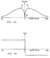
- FIGS. 3a-3d shows plots of the amplitudes and phases of the signals on leads 64 and 66 received by the parallel receive coil 42 and the perpendicular receive coil 44, respectively, versus the relative position of the receive coils with respect to the transmit coil 36.
- the signal transmitted by the transmit coil 36 is supplied by leads 62.
- the signal transmitted by the transmit coil 36, and received by the parallel receive coil 42 and perpendicular receive coil 44 will hereafter be referred to using the reference numbers of the corresponding leads, namely 62, 64 and 66, respectively.
- FIG. 3a is a graph of the amplitude of the signal 66 received by perpendicular receive coil 44 versus the relative longitudinal position of the perpendicular receive coil with respect to the center of the transmit coil 36.
- the amplitude of the perpendicular receive signal 66 has a null 68 when the relative position is zero (also called the "center" position, i.e., when the perpendicular receive coil 44 is longitudinally centered with respect to the transmit coil 36), increases to a local maximum value 70 on either side of the zero position, and then decays back toward zero as the distances increase to the right or left of the local maxima.
- FIG. 3b is a graph of the phase of the signal 66 received by the perpendicular receive coil 44 versus the relative longitudinal position of the perpendicular receive coil with respect to the center of the transmit coil 36.
- the phase of signal 66 is measured with respect to the phase of the signal 62 transmitted by transmit coil 36.
- the perpendicular receive signal 66 is in phase with the transmit coil signal 62 for negative relative distances (i.e., left of the zero position) and is out of phase for positive relative distances (i.e., right of the zero position).
- FIG. 3c is a graph of the amplitude of the signal 64 received by the parallel receive coil 42 versus the relative longitudinal position of the center of the parallel receive coil with respect to the center of the transmit coil 36.
- the amplitude signal 64 has a local maximum value 72 when the relative distance is zero (i.e., when the center of the parallel receive coil 42 is longitudinally centered with respect to the transmit coil 36), has nulls 74 at either side of the zero position, then has secondary maxima 76 as the distance from the zero position increases, and finally decays toward zero as the distance increases to the left and right of the secondary maxima 76.
- the zone 78 between the nulls 74 is referred to as the "near zone” and the zones 80 to the left and right of the nulls are referred to as the "far zone".
- FIG. 3d is a graph of the phase of the signal 64 received by the parallel receive coil 42 versus the relative longitudinal position of the center of parallel receive coil with respect to the center of the transmit coil 36. As before, the phase of signal 64 is measured with respect to the phase of the signal 62 transmitted by transmit coil 36. As shown in FIG. 3d, the parallel receive signal 64 is in phase with the transmit coil signal 62 in the far zones 80 and is out of phase within the near zone 78.
- the receive coils 42, 44 are mounted such that the perpendicular receive coil 44 is longitudinally centered with respect to the parallel receive coil 42, as shown in FIG. 2.
- Such a mounting arrangement will result in the longitudinal correspondence of the zero/center positions for the two receive coils, greatly simplifying the interpretation of the amplitude and phase relationships necessary to determine the position of the receive coils with respect to the transmit coil 36 (and hence, the position of the mandrel 20 with respect to the BCU 32).
- Detection of relative phase of the received low frequency signals 64, 66 requires knowledge of the phase of the transmitting signal 62.
- a replica of the transmitted signal 62 is therefore maintained in the MCU 34 as a local reference for phase computation purposes.
- This local reference is continuously adjusted to match the timing of the transmitting signal 62 by means of information received over the DSS radio link 56. Since there is an inherent and variable delay in the DSS radio channel due to software buffering, error correction and channel hopping, the BCU 32 accounts for these delays by keeping a history (e.g., in the form of a running average or other statistical value) of the communication round trip times, i.e., the RT times.
- the reference phase information transmitted by the BCU 32 to the MCU 34 over the DSS channel is then pre-adjusted by one-half the average round trip delay time (i.e., by 0.5 x ART) such that the phase information received by the MCU 34 will allow accurate determination of the phases of the received signals 64, 66.
- the MCU 34 amplifies, filters and digitizes the low frequency electromagnetic signals 64, 66 detected by the parallel and perpendicular receive coils 42, 44.
- the perpendicular receive coil signal 66 is digitized and then cross correlated with various time shifted versions of the local reference. The maximum cross correlation result corresponds to the best match of the signals being correlated. The relative phase information between the transmit coil signal and perpendicular receive coil signal is thus determined.
- the parallel coil signal 64 is also processed in a similar fashion to determine the parallel phase. The best correlation match also provides amplitude information for both the receive coils 42, 44.
- the phase information from both receive coils is used by computer control unit 48 to uniquely determine which zone (i.e., near zone left of center, near zone right of center, far zone left of center, far zone right of center) of the relative position the mandrel occupies.
- the amplitude ratios i.e., between the two receive coil signals 64, 66
- position estimation is based on amplitude ratios rather than absolute values, the estimation is robust and immune to small variations in signal strength and quality.
- FIG. 4 shows a block diagram of a BCU 32 according to one embodiment of the current invention.
- the BCU 32 includes a digital signal processor ("DSP") 82, a power driver 84 for energizing the transmit coil 36, and the direct sequence spread spectrum radio modem 38.
- the DSP 82 is operably connected to the power driver 84 by means of optical isolation unit 86.
- the DSS radio modem 38 which is operably connected to the DSP 82 by means of an optical isolation unit 88 and a universal asynchronous receiver/transmitter (“UART”) 90, transmits and receives through antenna 52.
- UART universal asynchronous receiver/transmitter
- a user control panel 92 is operably connected to the DSP 82 by means of optical isolation unit 96 for providing digital and analog inputs (denoted generally by reference numeral 94) to the DSP.
- Indicators 98 are operably connected to the DSP 82 for receiving signals from the DSP indicating the status ofthe system components and the position of the mandrel 20 within the pipe 22. The indicators 98 are preferably, although not necessarily, located on the control panel 92.
- An asynchronous serial link 100 operably connected to the DSP 82 by means of optical isolation unit 102 and UART 104, is provided for diagnostics and maintenance, for example, to allow field software upgrades to be uploaded to the DSP.
- FIG. 5 shows a block diagram of the MCU 34 according to one embodiment of the current invention.
- the MCU 34 includes a digital signal processor 106, receive signal conditioning equipment, and a DSS radio modem 46.
- the signal 64 received by the parallel receive coil 42 is conditioned by a differential amplifier 108 and a band pass filter 110 before being digitized by an analog-to-digital converter 112 and delivered to DSP 106.
- the signal 66 received by the perpendicular receive coil 44 is conditioned by a differential amplifier 114 and a band pass filter 116 before being digitized by an analog-to-digital converter 118 and delivered to the DSP 106.
- the DSS radio modem 48 which is operably connected to the DSP 106 by means of an optical isolation unit 120 and a UART 122, transmits and receives through antenna 54.
- Analog and digital output signals (denoted generally by reference number 124) from the DSP 106 pass through an optical isolation unit 126 for controlling mandrel functions such as extension and retraction of the shoes 24, operation of the wheels 28, and control of the engine power unit 30.
- DSP 106 can activate relays 128 to control other functions on the mandrel.
- External control inputs and feedback signals from the control system (denoted generally by reference numeral 130) are fed into the DSP 106 by means of optical isolation unit 132.
- An asynchronous serial link 134 operably connected to the DSP 106 by means of optical isolation unit 136 and UART 138, is provided for diagnostics and maintenance.
- Pipe bending operations involve repeated precise position of the mandrel 20 within the pipe 22.
- the apparatus of the current invention eliminates the need for a dedicated mandrel operator to assist the bender apparatus operator by automating the positioning of the mandrel within the pipe.
- a single command by the operator at the BCU console 92 will cause the mandrel 20 to retract the supporting shoes 24, move right or left (i.e., longitudinally) through the pipe 22 as necessary to center itself with respect to the transmit coil 36 (e.g., to longitudinally center the receive coils 42, 44 with the transmit coil 36) and then to extend the shoes into engagement with the pipe wall 26 to provide support for the next bend operation.
- the current mandrel position (with respect to the center position as defined by the transmit coil 36) as reported by the MCU 34 is used by the BCU to compute the power drive applied to the hydraulic proportional valve (not shown) which controls the mandrel forward/reverse motion.
- This computation is preferably based on a conventional Proportional-Integral-Derivative (PID) control algorithm, however, other algorithms known in the art for positioning control can be used.
- PID Proportional-Integral-Derivative
- FIG. 6 provides a block diagram flow chart of the steps comprising an automated bend operation.
- the automated bend procedure begins with a check to determine whether the MCU 34 mounted on the mandrel is within range of the BCU 32 mounted on the bending machine.
- the range check comprises determining if the received signal quality and strength of both the parallel receive coil signal 64 and the perpendicular receive coil signal 66 are sufficient to reliably determine the relative positions between the transmit coil 36 and the receive coils 42, 44: If the signals are sufficient, this is considered an "in range” condition, and the procedure advances to block 202; while if either signal is not sufficient, an "out of range” condition exists and the bend operation is aborted to block 204.
- an "in range” condition is indicated by continuously lighting a RANGE light 302 on the BCU control panel 92, and an "out of range” condition is indicated by blinking the RANGE light. Aborting the procedure to block 204 disables further automatic operation until an "in range” condition is established.
- the procedure waits until a NEXT PULL signal is received from the control panel 92.
- the NEXT PULL signal is produced when the INCREMENT button is pushed on the control panel 92 during automatic mode of operation (selected by CONTROL MODE switch 306).
- the procedure advances to block 206, wherein the BCU commands (via radio link 56) the MCU 34 to retract the shoes 24 of the mandrel.
- the procedure then advances to block 208, where the procedure checks to determine if the shoes 24 have been retracted. In the preferred embodiment, this check is performed by monitoring low side pressure input to the shoe mechanism.
- Block 212 is simply a timing loop, i.e., if the automatic operation takes more than a preset time limit, this is regarded as a "timeout" condition and the procedure aborts to block 214. Otherwise, the timing loop returns to block 208 to update the shoe position check.
- the position of the mandrel shoes 24 is indicated on the control panel 92 by the UP light 308 and the DOWN light 310.
- the procedure checks to determine if the BCU 32 has valid mandrel position value which has been received from the MCU 34. If so, the procedure advances to block 218, otherwise, the procedure aborts to block 216. Aborting the procedure to block 216 disables further automatic operation until an valid position is received.
- the BCU 32 transmits movement commands to the MCU 34 as necessary to move the mandrel 20 to the center position (i.e., zero position) with respect to the transmit coil 36.
- the parameters of the movement commands e.g., direction, speed
- the movement command resulting from the control algorithm is then transmitted by the BCU to the MCU over the radio link 56.
- the movement command causes the MCU to produce digital or analog outputs which activate the mandrel controls for forward and reverse motion.
- the mandrel's position is continuously updated to the BCU over the radio link 56 and the new positions are used as feedback in the control algorithm to adjust subsequent movement commands. The feedback control continues until the mandrel stabilizes at the center/zero position.
- the procedure has meanwhile advanced to block 220, where a check is performed to determine whether the mandrel has achieved the center position. If so, the procedure advances to block 226, while if not, the procedure enters a timing loop through block 222 and back to block 218. If the automatic centering operation takes more than a preset time limit, this is regarded as a "timeout" condition and the procedure aborts to block 224.
- the BCU 32 commands (via radio link 56) the MCU 34 to extend the shoes 24 of the mandrel.
- the procedure then advances to block 228, where the procedure checks to determine if the shoes 24 have been extended. In the preferred embodiment, this check is performed by monitoring high side pressure input to the shoe mechanism. If the check determines the shoes 24 are extended (i.e., up), then the procedure advances to block 230 (end of the bend procedure), while if the check determines that the shoes are still retracted (i.e., down), then the procedure advances to block 232.
- Block 232 is another timing loop. If the automatic "shoes up" operation takes more than a preset time limit, this is regarded as a "timeout" condition and the procedure aborts to block 234. Otherwise, the timing loop returns to block 228 to update the shoe position check.
- the procedure includes periodic checks for error conditions including loss of radio communication, poor signal quality or strength at the receive coils 42, 44, excessive time required for automatic operation, emergency stop by BCU operator, manual override control inputs by BCU operator.
- error conditions including loss of radio communication, poor signal quality or strength at the receive coils 42, 44, excessive time required for automatic operation, emergency stop by BCU operator, manual override control inputs by BCU operator.
- the determination that any of such error conditions exists causes premature termination of the automatic mode of operation and/or shutdown of controls for safety purposes.
- short-term error conditions trigger the shutdown of hydraulic control signals for shoes up/down and forward/reverse motion of the mandrel. If the error conditions persist for more than a pre-determined time, the mandrel engine is shutdown for safety purposes.
- FIG. 7 the control layout of the BCU control panel 92 for the preferred embodiment is shown.
- Numerous indicators of system status are provided, including a COM light 312 (lit when radio link operating), the RANGE light 302 (lit when valid position information available), an AUTO light 314 (lit to indicate automatic mode enabled), a LEFT light 316 (lit to show when mandrel detected passing the center position from right to left), a RIGHT light 318 (lit to show when mandrel detected passing the center position from left to right), the UP light 308 and the DOWN light 310 lit to show the position of the mandrel shoes 24.
- COM light 312 lit when radio link operating
- the RANGE light 302 lit when valid position information available
- an AUTO light 314 lit to indicate automatic mode enabled
- a LEFT light 316 lit to show when mandrel detected passing the center position from right to left
- a RIGHT light 318 lit to show when mandrel detected passing the center position from left to right
- Switches are provided to activate various system functions, including SYSTEM switch 322 (turns system on/off), CONTROL MODE switch 306 (selects automatic/manual mode), ENGINE START switch 324 (turns mandrel engine on), ENGINE STOP switch 326 (turns mandrel engine off), and INCREMENT switch 304 (advances pipe in bender to next bending position, and if in automatic mode, initiates automatic mandrel centering procedure).
- a control joystick 328 is provided, allowing the bender operator to remotely control the mandrel movement (forward/reverse, i.e., right/left with respect to zero position) and shoe position as necessary.
- an emergency switch 330 is provided to shut down the system.
Landscapes
- Engineering & Computer Science (AREA)
- General Engineering & Computer Science (AREA)
- Chemical & Material Sciences (AREA)
- Combustion & Propulsion (AREA)
- Mechanical Engineering (AREA)
- Bending Of Plates, Rods, And Pipes (AREA)
- Near-Field Transmission Systems (AREA)
- Heating, Cooling, Or Curing Plastics Or The Like In General (AREA)
- Control And Safety Of Cranes (AREA)
- Lining Or Joining Of Plastics Or The Like (AREA)
Claims (2)
- Vorrichtung zur Steuerung der Position von einem Biegedorn (20) in einem Rohr (22), mit:einer externen Steuereinheit (32), die einen Niederfrequenz-Signalgenerator, eine Sendespule (36) und einen ersten Radiofrequenz-Transceiver (38) aufweist,
wobei die Sendespule (36) in der Nähe der äußeren Fläche von einer Wand (26) von dem Rohr (22) angeordnet ist und eine Längsachse hat, die parallel zu der Längsachse (50) von dem Rohr (22) ausgerichtet ist,
wobei der Signalgenerator funktional mit der Sendespule (36) verbunden ist, um elektromagnetische Niederfrequenz-Signale (60) durch die Wand (26) zu senden,
wobei der Radiofrequenz-Transceiver (38) ein Radiofrequenz-Signal (56) sendet,einer internen Steuereinheit (34), die an dem Biegedorn (20) montiert ist und eine erste Empfangsspule (42), eine zweite Empfangsspule (44) und einen zweiten Radiofrequenz-Transceiver (46) aufweist,
wobei die erste Empfangsspule (42) eine Längsachse hat, die parallel zu der Längsachse (50) von dem Rohr (22) ausgerichtet ist, wobei die Spule (42) dazu ausgestaltet ist, um die elektromagnetischen Niederfrequenz-Signale (60) zu empfangen, die durch die Wand (26) übertragen werden,
wobei die zweite Empfangsspule (44) eine Längsachse hat, die senkrecht zu der Längsachse (50) von dem Rohr (22) ausgerichtet ist, wobei die Spule (44) dazu ausgestaltet ist, um die elektromagnetischen Niederfrequenz-Signale (60) zu empfangen, die durch die Wand (26) übertragen werden,
wobei der zweite Radiofrequenz-Transceiver (46) dazu ausgestaltet ist, um das Radiofrequenz-Signal (56) zu empfangen, das Informationen bezüglich der Phase des Niederfrequenz-Signals enthält, undeinem digitalen Signalprozessor, der dazu ausgestaltet ist, um die Phase von Signalen (60), die von der ersten und der zweiten Empfangsspule (42, 44) empfangen werden, mit einer Zeitbasis zu vergleichen, die Informationen bezüglich der Phase des Niederfrequenz-Signals (56) enthält, das von dem ersten Radiofrequenz-Transceiver (38) empfangen wird. - Vorrichtung zur Steuerung der Position von einem Biegedorn (20) in einem Rohr (22) nach Anspruch 1, wobei der digitale Signalprozessor außerdem dazu ausgestaltet ist, um die Amplitude von dem Signal, das von einer von der ersten und der zweiten Empfangsspule (42, 44) empfangen wird, mit der Amplitude des Signals zu vergleichen, das von der anderen von der ersten und der zweiten Empfangsspule (42, 44) empfangen wird.
Applications Claiming Priority (3)
| Application Number | Priority Date | Filing Date | Title |
|---|---|---|---|
| US09/301,429 US6092406A (en) | 1999-04-28 | 1999-04-28 | Pipeline mandrel positioning control system |
| US301429 | 1999-04-28 | ||
| PCT/US2000/011536 WO2000065271A1 (en) | 1999-04-28 | 2000-04-26 | Pipeline mandrel positioning control system |
Publications (2)
| Publication Number | Publication Date |
|---|---|
| EP1171736A1 EP1171736A1 (de) | 2002-01-16 |
| EP1171736B1 true EP1171736B1 (de) | 2004-01-07 |
Family
ID=23163314
Family Applications (1)
| Application Number | Title | Priority Date | Filing Date |
|---|---|---|---|
| EP00926474A Expired - Lifetime EP1171736B1 (de) | 1999-04-28 | 2000-04-26 | System zur positionierung eines biegedorns in rohren |
Country Status (8)
| Country | Link |
|---|---|
| US (2) | US6092406A (de) |
| EP (1) | EP1171736B1 (de) |
| AT (1) | ATE257567T1 (de) |
| AU (1) | AU4499800A (de) |
| CA (1) | CA2371307C (de) |
| DE (1) | DE60007624T2 (de) |
| MX (1) | MXPA01010956A (de) |
| WO (1) | WO2000065271A1 (de) |
Families Citing this family (13)
| Publication number | Priority date | Publication date | Assignee | Title |
|---|---|---|---|---|
| DE10220676B4 (de) | 2002-05-10 | 2004-08-12 | Eisenmann Lacktechnik Kg | Einrichtung zur Bestimmung der Position eines Molches |
| RU2206815C1 (ru) * | 2002-05-29 | 2003-06-20 | ЗАО "Нефтегазкомплектсервис" | Устройство для индикации положения внутритрубных объектов и способ его применения (варианты) |
| RU2210020C1 (ru) * | 2002-05-29 | 2003-08-10 | ЗАО "Нефтегазкомплектсервис" | Устройство для индикации положения внутритрубных объектов |
| US6915943B2 (en) * | 2002-11-27 | 2005-07-12 | Crc-Evans Pipeline International, Inc. | Tetherless internal line-up unit for pipeline welding |
| NO325436B1 (no) * | 2005-10-04 | 2008-05-05 | Tdw Offshore Services As | Fremgangsmate og pluggtog for posisjonering ved onsket posisjon i en rorledning |
| US7302823B1 (en) * | 2006-07-06 | 2007-12-04 | Crc-Evans Pipeline International, Inc. | Gauge for pipe bending machine |
| RU2321027C1 (ru) * | 2006-07-20 | 2008-03-27 | Общество с ограниченной ответственностью фирма "Саратовгазприборавтоматика" | Устройство сигнализации прохождения по трубопроводу магнитонесущего инспекционного снаряда |
| DE102007004820A1 (de) * | 2007-01-31 | 2008-08-07 | Schwing Gmbh | Verfahren und Vorrichtung zur Reinigung einer Dickstoffförderleitung, insbesondere zur Förderung von Beton |
| US8683839B2 (en) * | 2010-12-30 | 2014-04-01 | Eaton Corporation | Internal roller swaging device and method |
| US9682413B2 (en) | 2010-12-30 | 2017-06-20 | Eaton Corporation | Internal roller swaging device and method |
| DE102019111885A1 (de) * | 2019-05-07 | 2020-11-12 | Pipetronics Gmbh & Co. Kg | Vorrichtung zum Sanierung von Leitungen mit einem Neigungssensor |
| RU199355U1 (ru) * | 2019-12-26 | 2020-08-28 | Общество с ограниченной ответственностью "Газпром трансгаз Ухта" | Портативный сигнализатор прохождения внутритрубного устройства |
| DE102020108425A1 (de) * | 2020-03-26 | 2021-09-30 | Sms Group Gmbh | Ziehmaschine, Ziehverfahren sowie Ziehdorn |
Family Cites Families (16)
| Publication number | Priority date | Publication date | Assignee | Title |
|---|---|---|---|---|
| US3747054A (en) * | 1970-01-05 | 1973-07-17 | Monroe X Ray Co | Wireless control of machines inside a pipeline |
| US3705506A (en) * | 1971-03-31 | 1972-12-12 | Crc Crose Int Inc | Automatic positioning device |
| US3949292A (en) * | 1974-03-15 | 1976-04-06 | Vetco Offshore Industries, Inc. | Pipeline inspection device with pivotal support structure |
| GB2038585B (en) | 1978-12-19 | 1983-04-27 | Walker P | Duct-tracing apparatus |
| JPH0289724A (ja) | 1988-09-27 | 1990-03-29 | Makoto Watanabe | 輸送システム |
| GB8913319D0 (en) * | 1989-06-09 | 1989-07-26 | British Gas Plc | Moling system |
| US5038107A (en) * | 1989-12-21 | 1991-08-06 | Halliburton Logging Services, Inc. | Method and apparatus for making induction measurements through casing |
| JP2935733B2 (ja) * | 1990-10-03 | 1999-08-16 | 高千穂産業株式会社 | 掘進ヘッドの位置検出装置 |
| US5320180A (en) * | 1992-10-08 | 1994-06-14 | Sharewell Inc. | Dual antenna radio frequency locating apparatus and method |
| US5469155A (en) | 1993-01-27 | 1995-11-21 | Mclaughlin Manufacturing Company, Inc. | Wireless remote boring apparatus guidance system |
| GB9413141D0 (en) * | 1994-06-30 | 1994-08-24 | Exploration And Production Nor | Downhole data transmission |
| DE4438934C1 (de) * | 1994-10-31 | 1995-11-16 | Tracto Technik | Ortungsvorrichtung für Rammbohrgeräte |
| US5585790A (en) * | 1995-05-16 | 1996-12-17 | Schlumberger Technology Corporation | Method and apparatus for determining alignment of borehole tools |
| US5651638A (en) * | 1995-09-01 | 1997-07-29 | Crc-Evans Pipeline International, Inc. | Method and apparatus for controlling the position and operation of equipment within a pipeline |
| US5697240A (en) * | 1996-10-08 | 1997-12-16 | Sabre International, Inc. | Method of determining the bend in a section of pipe |
| US6253595B1 (en) * | 1999-09-21 | 2001-07-03 | Crc-Evans Pipeline International, Inc. | Automated pipe bending machine |
-
1999
- 1999-04-28 US US09/301,429 patent/US6092406A/en not_active Expired - Lifetime
-
2000
- 2000-01-12 US US09/481,900 patent/US6354123B1/en not_active Expired - Lifetime
- 2000-04-26 EP EP00926474A patent/EP1171736B1/de not_active Expired - Lifetime
- 2000-04-26 WO PCT/US2000/011536 patent/WO2000065271A1/en not_active Ceased
- 2000-04-26 CA CA002371307A patent/CA2371307C/en not_active Expired - Fee Related
- 2000-04-26 AU AU44998/00A patent/AU4499800A/en not_active Abandoned
- 2000-04-26 MX MXPA01010956A patent/MXPA01010956A/es active IP Right Grant
- 2000-04-26 AT AT00926474T patent/ATE257567T1/de not_active IP Right Cessation
- 2000-04-26 DE DE60007624T patent/DE60007624T2/de not_active Expired - Fee Related
Also Published As
| Publication number | Publication date |
|---|---|
| US6092406A (en) | 2000-07-25 |
| CA2371307C (en) | 2007-10-02 |
| DE60007624D1 (de) | 2004-02-12 |
| CA2371307A1 (en) | 2000-11-02 |
| AU4499800A (en) | 2000-11-10 |
| MXPA01010956A (es) | 2002-05-06 |
| EP1171736A1 (de) | 2002-01-16 |
| ATE257567T1 (de) | 2004-01-15 |
| DE60007624T2 (de) | 2004-12-23 |
| WO2000065271A1 (en) | 2000-11-02 |
| US6354123B1 (en) | 2002-03-12 |
Similar Documents
| Publication | Publication Date | Title |
|---|---|---|
| US6092406A (en) | Pipeline mandrel positioning control system | |
| EP2168258B1 (de) | Systeme und verfahren zur unterdrückung von funkverbindungsinterferenzen in der mobilen satellitenkommunikaton | |
| EP4254734A3 (de) | Verfahren und vorrichtung zur steuerung der drahtlosen stromübertragung | |
| US6915943B2 (en) | Tetherless internal line-up unit for pipeline welding | |
| EP0255628A3 (de) | Umlegeeinrichtung und Verfahren zur Interferenzverminderung für ein Funksystem | |
| KR101303911B1 (ko) | 추종 로봇 | |
| EP1043844A3 (de) | Verfahren zur Leistungsregelung in Systemen mit gespreiztem Spektrum | |
| JPH08316918A (ja) | 管内電波の送信方法 | |
| EP2079065A3 (de) | Systeme und Verfahren zur Fernsteuerung eines Materialhandhabungsfahrzeugs | |
| CA2450146A1 (en) | Device and method for positioning | |
| KR101753278B1 (ko) | 진단 로봇과 극저주파 자기장을 이용한 관로 위치 탐사 시스템 및 이를 이용한 위치 탐사 방법 | |
| US5651638A (en) | Method and apparatus for controlling the position and operation of equipment within a pipeline | |
| EP1087544A3 (de) | Verfahren und Vorrichtung zur adaptiven Änderung eines Benutzer-Prüfsignals | |
| CN114610079A (zh) | 一种基于极低频磁传感的二维控制方法及系统 | |
| JP3805054B2 (ja) | 自己調整gps基準ステーションおよび該ステーションを作動させるための方法 | |
| EP3849053B1 (de) | Kommunikationssteuerungsvorrichtung | |
| JPH06109862A (ja) | 埋設管に於ける対象個所の検知方法 | |
| CN218883432U (zh) | 一种具有越障功能的自走型地下管线探测仪 | |
| JP3010591U (ja) | ポンプ車用放水銃の吐水圧力自動制御装置 | |
| CN211125082U (zh) | 一种可以自动爬行的移动电缆 | |
| JP3648167B2 (ja) | 埋設管の位置検出方法及び検出装置 | |
| KR101953023B1 (ko) | 강도측정기를 포함하는 하수관로 탐사장비 | |
| KR200275257Y1 (ko) | 관로 탐색용 자주차의 원격제어장치 | |
| JP3764993B2 (ja) | 火災用ロボット設備 | |
| JPH08101269A (ja) | トランスポンダを搭載したピグの走行監視システム |
Legal Events
| Date | Code | Title | Description |
|---|---|---|---|
| PUAI | Public reference made under article 153(3) epc to a published international application that has entered the european phase |
Free format text: ORIGINAL CODE: 0009012 |
|
| 17P | Request for examination filed |
Effective date: 20011122 |
|
| AK | Designated contracting states |
Kind code of ref document: A1 Designated state(s): AT BE CH CY DE DK ES FI FR GB GR IE IT LI LU MC NL PT SE |
|
| AX | Request for extension of the european patent |
Free format text: AL;LT;LV;MK;RO;SI |
|
| GRAH | Despatch of communication of intention to grant a patent |
Free format text: ORIGINAL CODE: EPIDOS IGRA |
|
| GRAS | Grant fee paid |
Free format text: ORIGINAL CODE: EPIDOSNIGR3 |
|
| GRAA | (expected) grant |
Free format text: ORIGINAL CODE: 0009210 |
|
| AK | Designated contracting states |
Kind code of ref document: B1 Designated state(s): AT BE CH CY DE DK ES FI FR GB GR IE IT LI LU MC NL PT SE |
|
| PG25 | Lapsed in a contracting state [announced via postgrant information from national office to epo] |
Ref country code: LI Free format text: LAPSE BECAUSE OF FAILURE TO SUBMIT A TRANSLATION OF THE DESCRIPTION OR TO PAY THE FEE WITHIN THE PRESCRIBED TIME-LIMIT Effective date: 20040107 Ref country code: CH Free format text: LAPSE BECAUSE OF FAILURE TO SUBMIT A TRANSLATION OF THE DESCRIPTION OR TO PAY THE FEE WITHIN THE PRESCRIBED TIME-LIMIT Effective date: 20040107 Ref country code: CY Free format text: LAPSE BECAUSE OF FAILURE TO SUBMIT A TRANSLATION OF THE DESCRIPTION OR TO PAY THE FEE WITHIN THE PRESCRIBED TIME-LIMIT Effective date: 20040107 Ref country code: BE Free format text: LAPSE BECAUSE OF FAILURE TO SUBMIT A TRANSLATION OF THE DESCRIPTION OR TO PAY THE FEE WITHIN THE PRESCRIBED TIME-LIMIT Effective date: 20040107 Ref country code: AT Free format text: LAPSE BECAUSE OF FAILURE TO SUBMIT A TRANSLATION OF THE DESCRIPTION OR TO PAY THE FEE WITHIN THE PRESCRIBED TIME-LIMIT Effective date: 20040107 Ref country code: FI Free format text: LAPSE BECAUSE OF FAILURE TO SUBMIT A TRANSLATION OF THE DESCRIPTION OR TO PAY THE FEE WITHIN THE PRESCRIBED TIME-LIMIT Effective date: 20040107 Ref country code: NL Free format text: LAPSE BECAUSE OF FAILURE TO SUBMIT A TRANSLATION OF THE DESCRIPTION OR TO PAY THE FEE WITHIN THE PRESCRIBED TIME-LIMIT Effective date: 20040107 |
|
| REG | Reference to a national code |
Ref country code: GB Ref legal event code: FG4D |
|
| REG | Reference to a national code |
Ref country code: CH Ref legal event code: EP |
|
| REG | Reference to a national code |
Ref country code: IE Ref legal event code: FG4D |
|
| REF | Corresponds to: |
Ref document number: 60007624 Country of ref document: DE Date of ref document: 20040212 Kind code of ref document: P |
|
| PGFP | Annual fee paid to national office [announced via postgrant information from national office to epo] |
Ref country code: SE Payment date: 20040406 Year of fee payment: 5 |
|
| PG25 | Lapsed in a contracting state [announced via postgrant information from national office to epo] |
Ref country code: GR Free format text: LAPSE BECAUSE OF FAILURE TO SUBMIT A TRANSLATION OF THE DESCRIPTION OR TO PAY THE FEE WITHIN THE PRESCRIBED TIME-LIMIT Effective date: 20040407 Ref country code: SE Free format text: LAPSE BECAUSE OF FAILURE TO SUBMIT A TRANSLATION OF THE DESCRIPTION OR TO PAY THE FEE WITHIN THE PRESCRIBED TIME-LIMIT Effective date: 20040407 Ref country code: DK Free format text: LAPSE BECAUSE OF FAILURE TO SUBMIT A TRANSLATION OF THE DESCRIPTION OR TO PAY THE FEE WITHIN THE PRESCRIBED TIME-LIMIT Effective date: 20040407 |
|
| PG25 | Lapsed in a contracting state [announced via postgrant information from national office to epo] |
Ref country code: ES Free format text: LAPSE BECAUSE OF FAILURE TO SUBMIT A TRANSLATION OF THE DESCRIPTION OR TO PAY THE FEE WITHIN THE PRESCRIBED TIME-LIMIT Effective date: 20040418 |
|
| PGFP | Annual fee paid to national office [announced via postgrant information from national office to epo] |
Ref country code: DK Payment date: 20040419 Year of fee payment: 5 |
|
| NLV1 | Nl: lapsed or annulled due to failure to fulfill the requirements of art. 29p and 29m of the patents act | ||
| LTIE | Lt: invalidation of european patent or patent extension |
Effective date: 20040107 |
|
| REG | Reference to a national code |
Ref country code: CH Ref legal event code: PL |
|
| ET | Fr: translation filed | ||
| PLBE | No opposition filed within time limit |
Free format text: ORIGINAL CODE: 0009261 |
|
| STAA | Information on the status of an ep patent application or granted ep patent |
Free format text: STATUS: NO OPPOSITION FILED WITHIN TIME LIMIT |
|
| 26N | No opposition filed |
Effective date: 20041008 |
|
| PGFP | Annual fee paid to national office [announced via postgrant information from national office to epo] |
Ref country code: DE Payment date: 20070503 Year of fee payment: 8 |
|
| PGFP | Annual fee paid to national office [announced via postgrant information from national office to epo] |
Ref country code: MC Payment date: 20070510 Year of fee payment: 8 |
|
| PGFP | Annual fee paid to national office [announced via postgrant information from national office to epo] |
Ref country code: IE Payment date: 20070514 Year of fee payment: 8 |
|
| PGFP | Annual fee paid to national office [announced via postgrant information from national office to epo] |
Ref country code: LU Payment date: 20070524 Year of fee payment: 8 |
|
| PGFP | Annual fee paid to national office [announced via postgrant information from national office to epo] |
Ref country code: GB Payment date: 20070502 Year of fee payment: 8 |
|
| PG25 | Lapsed in a contracting state [announced via postgrant information from national office to epo] |
Ref country code: PT Free format text: LAPSE BECAUSE OF NON-PAYMENT OF DUE FEES Effective date: 20040607 |
|
| PGFP | Annual fee paid to national office [announced via postgrant information from national office to epo] |
Ref country code: IT Payment date: 20070529 Year of fee payment: 8 |
|
| PGFP | Annual fee paid to national office [announced via postgrant information from national office to epo] |
Ref country code: FR Payment date: 20070426 Year of fee payment: 8 |
|
| PG25 | Lapsed in a contracting state [announced via postgrant information from national office to epo] |
Ref country code: MC Free format text: LAPSE BECAUSE OF NON-PAYMENT OF DUE FEES Effective date: 20080430 |
|
| GBPC | Gb: european patent ceased through non-payment of renewal fee |
Effective date: 20080426 |
|
| PG25 | Lapsed in a contracting state [announced via postgrant information from national office to epo] |
Ref country code: DE Free format text: LAPSE BECAUSE OF NON-PAYMENT OF DUE FEES Effective date: 20081101 |
|
| REG | Reference to a national code |
Ref country code: FR Ref legal event code: ST Effective date: 20081231 |
|
| REG | Reference to a national code |
Ref country code: IE Ref legal event code: MM4A |
|
| PG25 | Lapsed in a contracting state [announced via postgrant information from national office to epo] |
Ref country code: IE Free format text: LAPSE BECAUSE OF NON-PAYMENT OF DUE FEES Effective date: 20080428 Ref country code: FR Free format text: LAPSE BECAUSE OF NON-PAYMENT OF DUE FEES Effective date: 20080430 |
|
| PG25 | Lapsed in a contracting state [announced via postgrant information from national office to epo] |
Ref country code: GB Free format text: LAPSE BECAUSE OF NON-PAYMENT OF DUE FEES Effective date: 20080426 |
|
| PG25 | Lapsed in a contracting state [announced via postgrant information from national office to epo] |
Ref country code: IT Free format text: LAPSE BECAUSE OF NON-PAYMENT OF DUE FEES Effective date: 20080426 |
|
| PG25 | Lapsed in a contracting state [announced via postgrant information from national office to epo] |
Ref country code: LU Free format text: LAPSE BECAUSE OF NON-PAYMENT OF DUE FEES Effective date: 20080426 |