EP1172260A2 - Pare-chocs pour automobile - Google Patents
Pare-chocs pour automobile Download PDFInfo
- Publication number
- EP1172260A2 EP1172260A2 EP01306030A EP01306030A EP1172260A2 EP 1172260 A2 EP1172260 A2 EP 1172260A2 EP 01306030 A EP01306030 A EP 01306030A EP 01306030 A EP01306030 A EP 01306030A EP 1172260 A2 EP1172260 A2 EP 1172260A2
- Authority
- EP
- European Patent Office
- Prior art keywords
- bumper
- wall
- core
- rib
- ribs
- Prior art date
- Legal status (The legal status is an assumption and is not a legal conclusion. Google has not performed a legal analysis and makes no representation as to the accuracy of the status listed.)
- Granted
Links
- 210000003195 fascia Anatomy 0.000 claims abstract description 31
- 230000008878 coupling Effects 0.000 claims description 18
- 238000010168 coupling process Methods 0.000 claims description 18
- 238000005859 coupling reaction Methods 0.000 claims description 18
- 230000003014 reinforcing effect Effects 0.000 claims description 10
- 229920005992 thermoplastic resin Polymers 0.000 claims description 9
- 238000000071 blow moulding Methods 0.000 claims description 5
- 238000004519 manufacturing process Methods 0.000 claims description 3
- 230000015572 biosynthetic process Effects 0.000 claims 1
- 238000003825 pressing Methods 0.000 claims 1
- 229920001169 thermoplastic Polymers 0.000 claims 1
- 239000004416 thermosoftening plastic Substances 0.000 claims 1
- 229920005989 resin Polymers 0.000 description 11
- 239000011347 resin Substances 0.000 description 11
- 238000010521 absorption reaction Methods 0.000 description 5
- 230000000694 effects Effects 0.000 description 5
- 239000011796 hollow space material Substances 0.000 description 5
- 239000006260 foam Substances 0.000 description 4
- 238000012986 modification Methods 0.000 description 3
- 230000004048 modification Effects 0.000 description 3
- -1 polypropylene Polymers 0.000 description 3
- 230000035939 shock Effects 0.000 description 3
- 229920000122 acrylonitrile butadiene styrene Polymers 0.000 description 2
- 230000008439 repair process Effects 0.000 description 2
- NLHHRLWOUZZQLW-UHFFFAOYSA-N Acrylonitrile Chemical compound C=CC#N NLHHRLWOUZZQLW-UHFFFAOYSA-N 0.000 description 1
- 239000004743 Polypropylene Substances 0.000 description 1
- PPBRXRYQALVLMV-UHFFFAOYSA-N Styrene Natural products C=CC1=CC=CC=C1 PPBRXRYQALVLMV-UHFFFAOYSA-N 0.000 description 1
- 229920000800 acrylic rubber Polymers 0.000 description 1
- XECAHXYUAAWDEL-UHFFFAOYSA-N acrylonitrile butadiene styrene Chemical compound C=CC=C.C=CC#N.C=CC1=CC=CC=C1 XECAHXYUAAWDEL-UHFFFAOYSA-N 0.000 description 1
- 239000004676 acrylonitrile butadiene styrene Substances 0.000 description 1
- 229920001893 acrylonitrile styrene Polymers 0.000 description 1
- 239000000853 adhesive Substances 0.000 description 1
- 238000004026 adhesive bonding Methods 0.000 description 1
- 230000001070 adhesive effect Effects 0.000 description 1
- 230000000712 assembly Effects 0.000 description 1
- 238000000429 assembly Methods 0.000 description 1
- 230000003139 buffering effect Effects 0.000 description 1
- 229920001577 copolymer Polymers 0.000 description 1
- 238000005516 engineering process Methods 0.000 description 1
- 229920001903 high density polyethylene Polymers 0.000 description 1
- 239000004700 high-density polyethylene Substances 0.000 description 1
- 239000000155 melt Substances 0.000 description 1
- 239000002184 metal Substances 0.000 description 1
- 238000000034 method Methods 0.000 description 1
- 239000000203 mixture Substances 0.000 description 1
- 238000000465 moulding Methods 0.000 description 1
- 229920000058 polyacrylate Polymers 0.000 description 1
- 229920006122 polyamide resin Polymers 0.000 description 1
- 229920001707 polybutylene terephthalate Polymers 0.000 description 1
- 229920005668 polycarbonate resin Polymers 0.000 description 1
- 239000004431 polycarbonate resin Substances 0.000 description 1
- 229920000139 polyethylene terephthalate Polymers 0.000 description 1
- 239000005020 polyethylene terephthalate Substances 0.000 description 1
- 229920001955 polyphenylene ether Polymers 0.000 description 1
- 229920001155 polypropylene Polymers 0.000 description 1
- SCUZVMOVTVSBLE-UHFFFAOYSA-N prop-2-enenitrile;styrene Chemical compound C=CC#N.C=CC1=CC=CC=C1 SCUZVMOVTVSBLE-UHFFFAOYSA-N 0.000 description 1
Images


Classifications
-
- B—PERFORMING OPERATIONS; TRANSPORTING
- B60—VEHICLES IN GENERAL
- B60R—VEHICLES, VEHICLE FITTINGS, OR VEHICLE PARTS, NOT OTHERWISE PROVIDED FOR
- B60R19/00—Wheel guards; Radiator guards, e.g. grilles; Obstruction removers; Fittings damping bouncing force in collisions
- B60R19/02—Bumpers, i.e. impact receiving or absorbing members for protecting vehicles or fending off blows from other vehicles or objects
- B60R19/18—Bumpers, i.e. impact receiving or absorbing members for protecting vehicles or fending off blows from other vehicles or objects characterised by the cross-section; Means within the bumper to absorb impact
-
- B—PERFORMING OPERATIONS; TRANSPORTING
- B60—VEHICLES IN GENERAL
- B60R—VEHICLES, VEHICLE FITTINGS, OR VEHICLE PARTS, NOT OTHERWISE PROVIDED FOR
- B60R19/00—Wheel guards; Radiator guards, e.g. grilles; Obstruction removers; Fittings damping bouncing force in collisions
- B60R19/02—Bumpers, i.e. impact receiving or absorbing members for protecting vehicles or fending off blows from other vehicles or objects
- B60R19/04—Bumpers, i.e. impact receiving or absorbing members for protecting vehicles or fending off blows from other vehicles or objects formed from more than one section in a side-by-side arrangement
-
- B—PERFORMING OPERATIONS; TRANSPORTING
- B60—VEHICLES IN GENERAL
- B60R—VEHICLES, VEHICLE FITTINGS, OR VEHICLE PARTS, NOT OTHERWISE PROVIDED FOR
- B60R19/00—Wheel guards; Radiator guards, e.g. grilles; Obstruction removers; Fittings damping bouncing force in collisions
- B60R19/02—Bumpers, i.e. impact receiving or absorbing members for protecting vehicles or fending off blows from other vehicles or objects
- B60R19/18—Bumpers, i.e. impact receiving or absorbing members for protecting vehicles or fending off blows from other vehicles or objects characterised by the cross-section; Means within the bumper to absorb impact
- B60R2019/1806—Structural beams therefor, e.g. shock-absorbing
- B60R2019/1833—Structural beams therefor, e.g. shock-absorbing made of plastic material
- B60R2019/184—Blow moulded
-
- B—PERFORMING OPERATIONS; TRANSPORTING
- B60—VEHICLES IN GENERAL
- B60R—VEHICLES, VEHICLE FITTINGS, OR VEHICLE PARTS, NOT OTHERWISE PROVIDED FOR
- B60R19/00—Wheel guards; Radiator guards, e.g. grilles; Obstruction removers; Fittings damping bouncing force in collisions
- B60R19/02—Bumpers, i.e. impact receiving or absorbing members for protecting vehicles or fending off blows from other vehicles or objects
- B60R19/18—Bumpers, i.e. impact receiving or absorbing members for protecting vehicles or fending off blows from other vehicles or objects characterised by the cross-section; Means within the bumper to absorb impact
- B60R2019/186—Additional energy absorbing means supported on bumber beams, e.g. cellular structures or material
- B60R2019/188—Blow molded structures
Definitions
- the present invention relates to a bumper for an automobile, and more particularly to a bumper core that is excellent in impact absorption and integrally disposed in the bumper.
- Automobile bumpers ideally provide protection in the event of serious collisions. It is also desired that the bumper have energy absorbing properties to lessen the severity of the accident.
- Bumpers should have the ability to deform during smaller accidents and to return to the original shape without incurring expensive repairs. In addition to these concerns, there are also automotive requirements that ensure the bumpers can withstand certain safety requirements.
- Front bumpers are usually configured to have greater rigidity in order to accommodate a more severe crash.
- Rear bumpers generally are made to absorb less severe crashes and to return to the original shape in minor collisions.
- the more common bumper has an outer shell and a rigid bumper beam.
- the bumper beam is a longitudinal reinforcing member, generally tubular, that is affixed to the car body. This metal reinforcing member provides the structural strength in the event of a collision. These are well known in the art and provide satisfactory protection for severe crashes. In minor collisions these bumpers tend to be easily dented and damaged. Thus, repair costs are higher on these vehicles, which affects insurance characteristics, such as the one disclosed in Japanese Patent Application Laid-open No. 3-125649.
- foam cores that are used primarily in rear bumpers, but also in some front bumpers depending upon the type of vehicle and the cost. It is well known in the industry that to enable a more satisfactory bumper design, it is necessary to combine an outer skin or fascia, some compressible impact absorbing member and a rigid longitudinal member. The foam cores provide some protection in minor crashes by returning the bumper to the original shape.
- the prior art describes automobile bumpers with an impact absorbing member and front and rear tubular beam reinforcing members disposed inside of a bumper fascia.
- the impact absorbing member and beam reinforcing member are both arranged inside the bumper fascia.
- the spacing between the bumper fascia and the car body is narrow, it is hard to obtain a sufficient thickness of the impact absorbing member and beam reinforcing member combined in the longitudinal direction for absorbing impact from the outside. This is particularly evident in the rear bumper having a thin and curved shape.
- These prior art bumper foam members also are expensive to manufacture and integrate into the bumper assemblies.
- the prior art foam core is expensive to integrate into a bumper and also has poor impact absorbing properties.
- the prior art design provides insufficient impact absorbing properties and the bumper is likely to suffer denting and damage from even low level impacts.
- What is needed is a bumper core that is cost-effective to manufacture and install within the bumpers. This bumper core should be designed to withstand significant impact forces and still return to the original shape of the bumper. Such a bumper should increase safety margins as well as lower insurance costs for minor collisions.
- the present invention has been achieved in view of the above-described problems of conventional technologies.
- the invention provides an automobile bumper, comprising a bumper fascia having at least one impact absorbing bumper core attached to an inner surface thereof, the bumper core comprising a hollow body defined by a surface wall attached to the bumper fascia, a rear wall opposed thereto, and a pair of opposed side walls, wherein at least one rib extends within the body from the surface wall to the rear wall.
- Automobile bumper cores may be interposed between the bumper fascia and the car body at the inside right and left positions as separate units.
- the bumper cores are suitably formed in a hollow double wall structure by blow moulding of thermoplastic resin as a moulded body having a hollow part and having side walls upright in the longitudinal direction of the bumper fascia. These units may be produced as separate units for the right and left sides of the bumper and easily installed by adhesive or other means known in the art.
- the automobile bumper cores of the present invention are preferably composed of thermoplastic resin, and more preferably a resin of which the modulus of flexural elasticity is 10000 kg/cm 2 to 40000 kg/cm 2 , and the overall mean wall thickness is 0.5 mm to 4.0 mm, and the product of modulus of flexural elasticity and mean wall thickness is 1000 kg/cm to 10000 kg/cm.
- the bumper fascia may be attached in a longitudinal manner to an automobile having a driver side section and a passenger side section, wherein said bumper core sections are affixed to said inner surface of the bumper fascia at a driver side and a passenger side.
- the rib for linking between the surface wall corresponding to the inside of the bumper fascia and the rear wall corresponding to the car body may be composed of plural concave ribs.
- the concave ribs are preferably formed in a circular or elliptical sectional shape.
- the bumper cores are preferably characterised by an integral structure in which the concave ribs composing the buffer section are formed from the surface wall and rear wall, abutting and fusing in the hollow space.
- the circular concave ribs preferably contract in diameter in the hollow space direction from the opening end of the surface wall or rear wall, the diameter of the contracting angle ⁇ being 5 to 30 degrees, and the diameter ⁇ of the opening end being 10 to 40 mm.
- part of the side wall of the bumper core is indented to the hollow space side to form ribs of the moulded body.
- the rib portion formed by indenting part of the side wall of the bumper core to the hollow space side may be semicircular, the rib portion being contracted in diameter in the hollow space direction from the opening end of the surface wall or rear wall of the impact absorbing member.
- the diameter of the contracting angle ⁇ is suitably 5 to 30 degrees, and the radius ⁇ of the opening end is suitably 5 to 20 mm.
- the bumper cores may have a plurality of coupling ribs for integrally linking the plurality of concave ribs.
- Each coupling rib of the bumper cores is preferably a longitudinal rib extending from the surface wall in the rear wall direction, or from the rear wall in the surface wall direction.
- the bumper of the invention provides impact absorbing qualities even in a structure with a thin bumper core in the longitudinal direction between the inside of the bumper fascia and car body, such as the rear bumper.
- a rear bumper 1 comprises a bumper fascia 2 and a pair of bumper cores 3 for absorbing impact from the outside.
- the bumper cores 3 are interposed at the right and left positions between the bumper fascia 2 and the car body.
- the bumper assembly of the present invention can also be attached to a longitudinal support that is part of the vehicle and provides greater collision safety.
- the right and left sides of the bumper fascia 2 are formed in a curvature along the side surface of the car body, and at the inside of the curved portions 4 there is an affixing portion 5 for affixing to the car body by screwing or fastening.
- the bumper fascia 2 is made of thermoplastic resin.
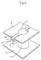
- the right bumper core 3 as seen from the inside of the bumper fascia 2 has a hollow part 6 in a hollow double wall structure by blow moulding of thermoplastic resin, and it is a closed hollow moulded body having upright side walls 7 in the longitudinal direction of the bumper fascia 2.
- This bumper core 3 has a rib 10 for linking between a surface wall 8 corresponding to the inside of the bumper fascia 2 and a rear wall 9 corresponding to the car body (not shown).
- the rib 10 is composed of concave ribs 10a, 10b formed respectively from the surface wall 8 and rear wall 9, being mutually fused inside the hollow portion 6 to be formed into an integral shape, and 10c is a fused plate portion.
- the concave ribs 10a, 10b are circular in sectional shape, but may be also formed in an elliptical sectional shape.
- the left bumper core 3 as seen from the inside of the bumper fascia 2 is symmetrical to the right bumper core 3 and is identical in structure.
- the bumper cores 3 are secured to the bumper fascia 2 by conventional means such as adhering or gluing. As the bumper cores are sectional, they can be asymmetrically designed for specific applications.
- the inclination angle ⁇ of the side wall 7 to the perpendicular line of the surface wall 8 is preferred to be 0 to 50 degrees in order to obtain a sufficient impact absorbing effect.
- the concave ribs 10a, 10b are frusto-conical shaped, being wider in diameter at the surface wall 8 or rear wall 9, as opposed to the centre at the fusing portion 10c.
- Such frusto-conical shape may have the appearance of a cup and have a flattened portion instead of a point at the smaller diameter.
- the angular dimension of the diameter contracting angle ⁇ is 5 to 30 degrees, and the diameter ⁇ of the opening end is 10 to 40 mm.
- the shape is shown as frusto-conical, the shape can encompass a sharp cone nose.
- the bumper cores 3 are composed of thermoplastic resin of which the modulus of flexural elasticity is 10000 kg/cm 2 to 40000 kg/cm 2 , and the overall mean wall thickness is 0.5 mm to 4.0 mm, the product of modulus of flexural elasticity and mean wall thickness being 1000 kg/cm to 10000 kg/cm.
- the modulus of flexural elasticity is the value established by testing according to the Japan Industrial Standard (JIS) K 7113. This testing methodology uses specimen type No. 2 and is measured at a pulling rate of 2 mm/min.
- thermoplastic resin for composing the bumper cores 3 examples include high density polyethylene resin, polypropylene resin, polyamide resin, polyethylene terephthalate resin, polybutylene terephthalate resin, polycarbonate resin, acrylonitrile butadiene styrene resin (ABS resin), acrylonitrile styrene resin (AS resin), acrylonitrile acrylic rubber styrene copolymer (AAS resin), polyphenylene ether resin (PPO resin), and their blends.
- ABS resin acrylonitrile butadiene styrene resin
- AS resin acrylonitrile styrene resin
- AAS resin acrylonitrile acrylic rubber styrene copolymer
- PPO resin polyphenylene ether resin
- Figure 4 shows a second embodiment of the right bumper core 3.
- the left bumper core 3 is symmetrical in shape, but is identical in structure.
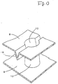
- a rib 10 is formed from a surface wall 8, and is fused to a rear wall 9, and a buffer portion is composed by the rib 10 which links the surface wall 8 and rear wall 9. There is no fused portion 10c as described in the first embodiment.
- Figure 5, Figure 6, and Figure 7 show other examples (third to fifth embodiments) of the bumper cores 3.
- the right bumper core 3 is shown, but the left bumper core 3 is symmetrical in shape, and is identical in structure.
- the rib 10 for linking a surface wall 8 and a rear wall 9 is formed as a perpendicular plate wholly within the hollow part 6. In this manner the rib 10 is termed an "inner rib" extending from the rear wall 9 to the surface wall 8, and its presence is not visible on the external surface of the mouldings, there being no resultant depressions on the surface.
- a plate 11 for reinforcing the inner rib is buried and the rib 10 is formed to provide a stronger reinforcing member between the surface wall 8 and a rear wall 9.
- the buried plate 11 is a thicker structure and provides greater reinforcing strength for the inner rib 10.
- the inner rib is not a concave structure but is as illustrated in the figures.
- the bumper core 3 shown in Figure 7 is a hollow double wall structure without the rib for linking between surface wall 8 and rear wall 9.
- the inclination angle ⁇ ' of the side wall 7 to the perpendicular line of the surface wall 8 is preferred to be 0 to 50 degrees in order to obtain a sufficient impact absorbing effect.
- Figures 8 to 11 relate to a sixth embodiment.
- Figure 8 is a front view of the bumper core as seen from the rear wall side.
- Figure 9 is a sectional view along line Y-Y in Figure 8.
- Figure 10 is a sectional view along line Z-Z in Figure 8, and
- Figure 11 is a perspective view of portions of Figure 8.
- the shape of the rib 10 is the same as the concave ribs 10a, 10b shown in Figure 3.
- one or more rib portions 12 also called side wall ribs are recessed in the hollow portion 6 and are formed at specified intervals.
- the side wall ribs 12 are semicircular, and are contracted in diameter in the hollow part direction from the opening end of the surface wall 8 or rear wall 9 of the bumper core 3, and the diameter contracting angle x is 5 to 30 degrees, and the radius y of the opening end is 5 to 20 mm.
- a plate or fusing portion 13 is formed nearly in the middle between the surface wall 8 and rear wall 9 in order to enhance the reinforcing effect.
- the multiple concave ribs 10a of the bumper core 3 of the sixth embodiment are integrally linked by coupling ribs 14 that join adjacent ribs together.
- the coupling rib 14, also called the "tie-up" rib is a longitudinal rib formed to extend in the direction of the rear wall 9 from the surface wall 8.
- the coupling rib 14 is formed like an inner rib with the longitudinal rib concealed in the hollow part 6 as shown in Figure 11. This inner coupling rib 14 is made by integrating two walls of the parison into a plate by air pressure after forming the concave portion from the surface wall 8 toward the hollow portion 6 in the blow moulding process.
- the coupling or tie-up rib 14 By using this coupling or tie-up rib 14, the position and direction of the concave ribs 10a can be held in a constant profile. As the shape and profile of concave rib 10a is maintained by this coupling rib 14, the properties and characteristics of the bumper core are consistent. In particular, from the viewpoint of buffering effect, the coupling rib 14 is preferred to be formed integrally with the concave ribs 10a at the surface wall 8 side as shown in Figure 11.
- the coupling rib 14 is formed in a groove or notch from the surface wall 8 side, and a plate 17 is formed from the bottom of the groove 16 disposed in the direction to the rear wall 9 side.
- the plate 17 is comprised of two walls pressed together by air and moulded into a single plate, wherein the dotted line represents the melt line.
- the coupling rib 14 is formed in a V-shaped groove, and by forming in this shape, the strength and rigidity of the bumper cores 3 are also enhanced.
- the automobile bumper according to the invention is intended to provide greater impact absorbing qualities from outside impact forces.
- the invention has bumper cores interposed between the bumper fascia and the car body at the inside right and left positions, and the bumper cores are closed moulded bodies formed in a hollow double wall structure by blow moulding of thermoplastic resin as a moulded body having a hollow part and having side walls upright in the longitudinal direction of the bumper fascia, and are therefore excellent in rigidity against impact and restoration after deformation in spite of small space in the longitudinal direction.
- the bumper cores of the bumper of the invention are composed of thermoplastic resin of which the modulus of flexural elasticity is 10000 kg/cm 2 to 40000 kg/cm 2 , and the overall mean wall thickness is 0.5 mm to 4.0 mm, the product of modulus of flexural elasticity and mean wall thickness being 1000 kg/cm to 10000 kg/cm, and therefore they are excellent in rigidity against impact and restoration after deformation. Further, by providing the structure forming the ribs for linking between the surface wall and rear wall of the bumper core, the rigidity against impact and restoration after deformation are further enhanced.
- the bumper cores of the bumper of the invention are closed moulded bodies having a buffer section composed of concave ribs for linking between the surface wall corresponding to the inside of the bumper fascia and the rear wall corresponding to the car body, or part of the side wall of the bumper cores is recessed to the hollow part side to be formed into rib-like moulded bodies, so that a higher impact absorption and safety may be obtained.
- the coupling rib is formed to join plural adjacent concave ribs mutually, the position and direction of the concave ribs can be held in a constant profile in the event of collision. This enables the bumper core to be positioned within the bumper fascia with the optimal impact absorption in a specific direction. Selective directional impact absorption can be accommodated by positioning the bumper core in the regions likely to receive impact.
Landscapes
- Engineering & Computer Science (AREA)
- Mechanical Engineering (AREA)
- Vibration Dampers (AREA)
- Vehicle Interior And Exterior Ornaments, Soundproofing, And Insulation (AREA)
- Blow-Moulding Or Thermoforming Of Plastics Or The Like (AREA)
- Body Structure For Vehicles (AREA)
- Mechanical Operated Clutches (AREA)
Applications Claiming Priority (8)
| Application Number | Priority Date | Filing Date | Title |
|---|---|---|---|
| JP2000215085 | 2000-07-14 | ||
| JP2000215085A JP4464539B2 (ja) | 2000-07-14 | 2000-07-14 | 自動車の衝撃吸収部材 |
| JP2000215084A JP2002029338A (ja) | 2000-07-14 | 2000-07-14 | 自動車のバンパー |
| JP2000215083 | 2000-07-14 | ||
| JP2000215084 | 2000-07-14 | ||
| JP2000215083A JP2002029339A (ja) | 2000-07-14 | 2000-07-14 | 自動車のバンパー |
| JP2000385930A JP4584444B2 (ja) | 2000-12-19 | 2000-12-19 | 自動車の衝撃吸収部材 |
| JP2000385930 | 2000-12-19 |
Publications (3)
| Publication Number | Publication Date |
|---|---|
| EP1172260A2 true EP1172260A2 (fr) | 2002-01-16 |
| EP1172260A3 EP1172260A3 (fr) | 2003-09-17 |
| EP1172260B1 EP1172260B1 (fr) | 2010-09-08 |
Family
ID=27481454
Family Applications (1)
| Application Number | Title | Priority Date | Filing Date |
|---|---|---|---|
| EP01306030A Expired - Lifetime EP1172260B1 (fr) | 2000-07-14 | 2001-07-12 | Pare-chocs pour automobile |
Country Status (7)
| Country | Link |
|---|---|
| US (1) | US6406079B2 (fr) |
| EP (1) | EP1172260B1 (fr) |
| CN (1) | CN1159178C (fr) |
| AT (1) | ATE480428T1 (fr) |
| AU (1) | AU2001271046A1 (fr) |
| DE (1) | DE60143003D1 (fr) |
| WO (1) | WO2002006089A1 (fr) |
Cited By (9)
| Publication number | Priority date | Publication date | Assignee | Title |
|---|---|---|---|---|
| WO2004040163A1 (fr) | 2002-10-31 | 2004-05-13 | Kyoraku Co., Ltd. | Absorbeur de chocs pour vehicule |
| WO2004080765A1 (fr) * | 2003-03-07 | 2004-09-23 | General Electric Company | Absorbeur d'energie moule par soufflage et destine a l'extremite avant d'un vehicule |
| EP1623880A4 (fr) * | 2003-05-14 | 2006-06-14 | Kyoraku Co Ltd | Amortisseur de voiture |
| WO2009006142A1 (fr) * | 2007-06-29 | 2009-01-08 | Dow Global Technologies, Inc. | Système d'applique de carénage frontal de pare-choc de véhicule |
| EP2022681A3 (fr) * | 2007-08-09 | 2009-11-25 | Magna International Inc. | Renfort de revêtement ferme formé sous vide pour carénage frontal de pare-chocs |
| EP1937466A4 (fr) * | 2005-09-20 | 2013-04-03 | Sport Helmets Inc | Materiau amortisseur a deplacement lateral |
| CN101622469B (zh) * | 2007-02-28 | 2013-04-24 | 京洛株式会社 | 车辆用冲击吸收体 |
| US8915536B2 (en) | 2010-05-28 | 2014-12-23 | Kyoraku Co., Ltd. | Impact absorbing member and method of manufacturing the same |
| US10357934B2 (en) | 2011-01-12 | 2019-07-23 | Abc Technologies Inc. | Hollow article with pillar structural members |
Families Citing this family (42)
| Publication number | Priority date | Publication date | Assignee | Title |
|---|---|---|---|---|
| DE60023025T2 (de) | 1999-11-23 | 2006-07-13 | Smithkline Beecham Corp. | 3,4-dihydro-(1h)chinazolin-2-on-verbindungen als csbp/p39-kinase-inhibitoren |
| US6406077B2 (en) * | 2000-05-11 | 2002-06-18 | Shape Corporation | Tube with extruded flanges holding wall-reinforcing insert |
| FR2815100B1 (fr) * | 2000-10-09 | 2003-04-18 | Sai Automotive Allibert Ind | Dispositif d'absorption d'energie lors d'un choc, et portiere de vehicule automobile comprenant un tel dispositif |
| EP1277621B1 (fr) * | 2001-07-17 | 2003-11-19 | Benteler Automobiltechnik GmbH | Pare-chocs pour véhicule automobile |
| WO2005012043A1 (fr) * | 2003-07-03 | 2005-02-10 | Netshape International, Llc | Systeme de pare-chocs incorporant des absorbeurs d'energie thermoformes |
| US8123263B2 (en) * | 2001-09-27 | 2012-02-28 | Shape Corp. | Energy management beam |
| CN100351121C (zh) * | 2003-05-14 | 2007-11-28 | 京洛株式会社 | 汽车冲击吸收体 |
| US20050097004A1 (en) * | 2003-10-29 | 2005-05-05 | Eduardo Masse Blume | Method of advertising and related products |
| JP4280153B2 (ja) * | 2003-11-28 | 2009-06-17 | キョーラク株式会社 | 車両用衝撃吸収体 |
| US7073831B2 (en) * | 2004-06-23 | 2006-07-11 | Netshape International Llc | Bumper with crush cones and energy absorber |
| US6971691B1 (en) * | 2004-06-25 | 2005-12-06 | Shape Corporation | Vehicle bumper beam |
| US7228723B2 (en) * | 2004-07-01 | 2007-06-12 | Netshape Energy Management Llc | Bumper impact-testing device |
| JP4531468B2 (ja) * | 2004-07-14 | 2010-08-25 | 小島プレス工業株式会社 | 車両用衝撃吸収構造体及びその取付構造 |
| US20060029728A1 (en) * | 2004-08-03 | 2006-02-09 | Roger Stull | Method of repair for plastic automotive body panels |
| JP4598468B2 (ja) * | 2004-09-30 | 2010-12-15 | キョーラク株式会社 | 車両用衝撃吸収体 |
| US7163243B2 (en) * | 2004-12-13 | 2007-01-16 | Netshape International, Llc | Bumper for pedestrian impact having thermoformed energy absorber |
| CN1295104C (zh) * | 2005-04-19 | 2007-01-17 | 蒋少鸣 | 弹性保险杠 |
| DE602005013523D1 (de) * | 2005-09-08 | 2009-05-07 | Ford Global Tech Llc | Blockanordnung zur Aufnahme von Stossenergien |
| US20100258988A1 (en) * | 2005-09-20 | 2010-10-14 | Sport Helmets, Inc. | Embodiments of Lateral Displacement Shock Absorbing Technology and Applications Thereof |
| JP4705829B2 (ja) * | 2005-09-22 | 2011-06-22 | ダイキョーニシカワ株式会社 | 樹脂パネル及びその製造方法 |
| US20080012365A1 (en) * | 2006-06-30 | 2008-01-17 | Harvey Steven M | Elastic vehicle bumper |
| JP4815387B2 (ja) * | 2007-04-25 | 2011-11-16 | 株式会社イノアックコーポレーション | 衝撃吸収部材 |
| FR2959190B1 (fr) * | 2010-04-23 | 2012-06-08 | Peugeot Citroen Automobiles Sa | Panneau de protection destine a etre fixe sur une partie de la carrosserie d'un vehicule automobile et vehicule equipe d'un tel panneau. |
| WO2012012535A2 (fr) * | 2010-07-21 | 2012-01-26 | Shape Corp. | Absorbeur d'énergie intégré et structure de gestion de l'écoulement de l'air |
| JP5516345B2 (ja) * | 2010-11-11 | 2014-06-11 | マツダ株式会社 | 車両用フレーム構造 |
| US9599181B2 (en) * | 2011-04-05 | 2017-03-21 | Kyoraku Co., Ltd. | Shock absorber |
| US10005408B2 (en) | 2011-11-03 | 2018-06-26 | Sabic Global Technologies B.V. | Energy absorbing system for conflicting regulatory requirements for vehicle bumpers |
| TWD160006S (zh) * | 2012-05-04 | 2014-04-21 | 福特環球科技有限公司 | 車輛下護柵 |
| CN102897123B (zh) * | 2012-09-26 | 2014-10-22 | 桐乡市小老板特种塑料制品有限公司 | 一种减缓碰撞力装置 |
| USD694679S1 (en) * | 2012-10-31 | 2013-12-03 | Ford Motor Company | Vehicle rear bumper cover molding |
| USD694678S1 (en) * | 2012-10-31 | 2013-12-03 | Ford Motor Company | Vehicle rear bumper cover cap |
| JP6093582B2 (ja) * | 2013-01-30 | 2017-03-08 | Ntn株式会社 | 回転伝達装置 |
| JP6390063B2 (ja) | 2013-09-26 | 2018-09-19 | キョーラク株式会社 | 衝撃吸収体 |
| DE102014011790A1 (de) | 2014-08-12 | 2016-02-18 | GM Global Technology Operations LLC (n. d. Ges. d. Staates Delaware) | Stoßfängermodul |
| DE102014016044A1 (de) | 2014-10-29 | 2016-05-04 | GM Global Technology Operations LLC (n. d. Ges. d. Staates Delaware) | Frontpartie eines Kraftfahrzeugs und Stoßfängeraussteifung dazu |
| CN105292028A (zh) * | 2015-10-10 | 2016-02-03 | 广东东箭汽车用品制造有限公司 | 一种聚乙烯吹塑成型汽车防护杠及其表面涂装方法 |
| WO2017086205A1 (fr) * | 2015-11-20 | 2017-05-26 | マツダ株式会社 | Structure d'élément d'absorption de choc pour véhicule |
| US10647283B2 (en) * | 2015-11-27 | 2020-05-12 | Kyoraku Co., Ltd. | Shock absorber |
| DE102016000515A1 (de) | 2016-01-19 | 2017-07-20 | GM Global Technology Operations LLC (n. d. Ges. d. Staates Delaware) | Stoßfängermodul |
| US10875481B2 (en) * | 2017-02-09 | 2020-12-29 | Honda Motor Co., Ltd. | Mounting structure for external environment detection device for vehicle |
| TR201908229A2 (tr) * | 2019-05-29 | 2019-07-22 | Tirsan Treyler Sanayi Ve Ticaret Anonim Sirketi | Mukaveti̇ arttirilmiş alümi̇nyum ekstrüzyon tampon profi̇li̇ |
| US20230173896A1 (en) * | 2020-06-30 | 2023-06-08 | Toray Industries, Inc. | Impact absorbing structure |
Citations (1)
| Publication number | Priority date | Publication date | Assignee | Title |
|---|---|---|---|---|
| JPH03125649A (ja) | 1989-10-11 | 1991-05-29 | Daikyo Inc | プラスチック製バンパーレインホースメント |
Family Cites Families (31)
| Publication number | Priority date | Publication date | Assignee | Title |
|---|---|---|---|---|
| US3666310A (en) | 1971-01-11 | 1972-05-30 | Gulf & Western Ind Prod Co | Shock absorbing bumper |
| US3856613A (en) | 1972-08-28 | 1974-12-24 | Mccord Corp | Compressible energy absorbing article |
| FR2288648A1 (fr) * | 1974-03-05 | 1976-05-21 | Peugeot & Renault | Pare-chocs composite absorbeur d'energie |
| US3933387A (en) * | 1975-03-10 | 1976-01-20 | General Motors Corporation | Thermoformed plastic energy absorber for vehicles |
| JPS56164853U (fr) * | 1980-05-12 | 1981-12-07 | ||
| IT1156345B (it) * | 1982-11-29 | 1987-02-04 | Safiplast Spa | Paraurti per autovetture con elemento tubolare interno di irrigidimento |
| US4652031A (en) | 1984-06-25 | 1987-03-24 | Michael Ladney | Vehicle bumper |
| NL8503352A (nl) * | 1985-12-05 | 1987-07-01 | Stamicarbon | Bumper. |
| US4904008A (en) | 1986-09-02 | 1990-02-27 | Concept Analysis Corporation | Molded one-piece bumper |
| JPS63188254U (fr) * | 1987-03-13 | 1988-12-02 | ||
| DE3723467C2 (de) | 1987-07-16 | 1995-09-07 | Fichtel & Sachs Ag | Vorrichtung zum Einstellen und Justieren der Pralldämpfer von Stoßfängersystemen für Kraftfahrzeuge |
| DE68907880T2 (de) * | 1988-12-24 | 1993-11-04 | Minoru Sangyo | Stossstange aus kunststoff. |
| DE3928060A1 (de) | 1989-08-25 | 1991-02-28 | Daimler Benz Ag | Stossfaenger fuer einen kraftwagen |
| US5005887A (en) | 1990-04-09 | 1991-04-09 | Davidson Textron Inc. | Energy absorbing bumper fastener system |
| JPH0592744A (ja) * | 1991-03-06 | 1993-04-16 | Idemitsu Petrochem Co Ltd | プラスチツクバンパービーム |
| JPH05319186A (ja) * | 1991-03-08 | 1993-12-03 | Suzuki Motor Corp | 車両用バンパー |
| JP3248694B2 (ja) * | 1991-04-08 | 2002-01-21 | アイシン精機株式会社 | 車両用バンパ装置 |
| US5269574A (en) | 1992-02-10 | 1993-12-14 | Exxon Chemical Patents Inc. | High performance vehicle bumper |
| DE4307836B4 (de) * | 1992-03-25 | 2005-09-29 | Volkswagen Ag | Träger zur Energieabsorption bei quer zu seiner Längsrichtung erfolgenden Stößen |
| JPH07205264A (ja) * | 1994-01-11 | 1995-08-08 | Nippon Steel Chem Co Ltd | 多層ブロー成形品 |
| JP3561007B2 (ja) * | 1994-10-12 | 2004-09-02 | 出光石油化学株式会社 | 樹脂製自動車用衝撃緩衝部材 |
| ES2129788T3 (es) * | 1994-12-23 | 1999-06-16 | Alusuisse Lonza Services Ag | Parachoques para vehiculos. |
| DE19511868A1 (de) | 1995-03-31 | 1996-10-02 | Daimler Benz Ag | Stoßstange |
| JP3229568B2 (ja) * | 1996-09-13 | 2001-11-19 | ジー・ピー・ダイキョー株式会社 | バンパレインフォースメント |
| US5799991A (en) * | 1996-10-23 | 1998-09-01 | Concept Analysis Corporation | Molded bumper system with reinforcement beam |
| US6199942B1 (en) * | 1998-02-04 | 2001-03-13 | Oakwood Energy Management, Inc. | Modular energy absorbing assembly |
| JPH11255048A (ja) * | 1998-03-10 | 1999-09-21 | Nippon Steel Corp | 補強構造を有する構造部材 |
| US6000738A (en) * | 1998-03-13 | 1999-12-14 | Chrysler Corporation | Force-absorbing vehicle bumper |
| FR2777615B1 (fr) * | 1998-04-15 | 2000-12-29 | Plastic Omnium Cie | Absorbeur de chocs a section ondulee et pare-chocs muni d'un tel absorbeur de chocs |
| FR2784151B1 (fr) * | 1998-10-01 | 2002-03-22 | Allibert Ind | Dispositif d'absorption d'energie lors d'un choc et son procede d'obtention |
| JP2000318549A (ja) * | 1999-05-14 | 2000-11-21 | Fuji Heavy Ind Ltd | 車両用バンパービームおよび車両用バンパー装置 |
-
2001
- 2001-07-11 US US09/903,232 patent/US6406079B2/en not_active Expired - Lifetime
- 2001-07-12 EP EP01306030A patent/EP1172260B1/fr not_active Expired - Lifetime
- 2001-07-12 AT AT01306030T patent/ATE480428T1/de not_active IP Right Cessation
- 2001-07-12 DE DE60143003T patent/DE60143003D1/de not_active Expired - Lifetime
- 2001-07-13 AU AU2001271046A patent/AU2001271046A1/en not_active Abandoned
- 2001-07-13 WO PCT/JP2001/006077 patent/WO2002006089A1/fr not_active Ceased
- 2001-07-13 CN CNB018027687A patent/CN1159178C/zh not_active Expired - Lifetime
Patent Citations (1)
| Publication number | Priority date | Publication date | Assignee | Title |
|---|---|---|---|---|
| JPH03125649A (ja) | 1989-10-11 | 1991-05-29 | Daikyo Inc | プラスチック製バンパーレインホースメント |
Cited By (12)
| Publication number | Priority date | Publication date | Assignee | Title |
|---|---|---|---|---|
| WO2004040163A1 (fr) | 2002-10-31 | 2004-05-13 | Kyoraku Co., Ltd. | Absorbeur de chocs pour vehicule |
| EP1557582A4 (fr) * | 2002-10-31 | 2006-05-24 | Kyoraku Co Ltd | Corps absorbeur de chocs pour vehicule |
| EP1557583A4 (fr) * | 2002-10-31 | 2006-07-12 | Kyoraku Co Ltd | Absorbeur de chocs pour vehicule |
| WO2004080765A1 (fr) * | 2003-03-07 | 2004-09-23 | General Electric Company | Absorbeur d'energie moule par soufflage et destine a l'extremite avant d'un vehicule |
| EP1623880A4 (fr) * | 2003-05-14 | 2006-06-14 | Kyoraku Co Ltd | Amortisseur de voiture |
| EP1937466A4 (fr) * | 2005-09-20 | 2013-04-03 | Sport Helmets Inc | Materiau amortisseur a deplacement lateral |
| CN101622469B (zh) * | 2007-02-28 | 2013-04-24 | 京洛株式会社 | 车辆用冲击吸收体 |
| WO2009006142A1 (fr) * | 2007-06-29 | 2009-01-08 | Dow Global Technologies, Inc. | Système d'applique de carénage frontal de pare-choc de véhicule |
| EP2022681A3 (fr) * | 2007-08-09 | 2009-11-25 | Magna International Inc. | Renfort de revêtement ferme formé sous vide pour carénage frontal de pare-chocs |
| US7726725B2 (en) | 2007-08-09 | 2010-06-01 | Magna International Inc. | Vacuum-formed “firm-feel” reinforcement for bumper fascias |
| US8915536B2 (en) | 2010-05-28 | 2014-12-23 | Kyoraku Co., Ltd. | Impact absorbing member and method of manufacturing the same |
| US10357934B2 (en) | 2011-01-12 | 2019-07-23 | Abc Technologies Inc. | Hollow article with pillar structural members |
Also Published As
| Publication number | Publication date |
|---|---|
| WO2002006089A1 (fr) | 2002-01-24 |
| AU2001271046A1 (en) | 2002-01-30 |
| EP1172260A3 (fr) | 2003-09-17 |
| US6406079B2 (en) | 2002-06-18 |
| EP1172260B1 (fr) | 2010-09-08 |
| CN1159178C (zh) | 2004-07-28 |
| CN1392847A (zh) | 2003-01-22 |
| DE60143003D1 (de) | 2010-10-21 |
| ATE480428T1 (de) | 2010-09-15 |
| US20020005644A1 (en) | 2002-01-17 |
Similar Documents
| Publication | Publication Date | Title |
|---|---|---|
| EP1172260B1 (fr) | Pare-chocs pour automobile | |
| CN100480101C (zh) | 车辆冲击吸收体 | |
| EP1557582B1 (fr) | Corps absorbeur de chocs pour vehicule | |
| CN100562453C (zh) | 车辆用冲击吸收体 | |
| EP1857327B1 (fr) | Assemblage de pare-choc de véhicule et véhicule correspondant doté dudit assemblage de pare-choc | |
| EP1623880B1 (fr) | Amortisseur de voiture | |
| EP2119935B1 (fr) | Corps d'absorption d'impact pour véhicule | |
| KR20050105274A (ko) | 차량에 부착되는 에너지 업소버 | |
| JP2005502523A (ja) | クラッシュカンを備えたバンパービーム | |
| JP5288996B2 (ja) | 車両用衝撃吸収体 | |
| JP4584444B2 (ja) | 自動車の衝撃吸収部材 | |
| JP5011516B2 (ja) | 車両用衝撃吸収体 | |
| WO2013150895A1 (fr) | Absorbeur de chocs | |
| JP4559200B2 (ja) | 衝撃吸収体 | |
| JP2011247384A (ja) | 衝撃吸収体 | |
| JP4464539B2 (ja) | 自動車の衝撃吸収部材 | |
| JP4662331B2 (ja) | 車両用衝撃吸収体 | |
| JP2009012765A (ja) | 車両用衝撃吸収体 | |
| JP2005132303A (ja) | 車両用衝撃吸収体 | |
| JP2004262343A (ja) | 車両用衝撃吸収体 | |
| KR100267622B1 (ko) | 자동차필러의충격흡수구조 | |
| JP2002029338A (ja) | 自動車のバンパー | |
| JP2007245790A (ja) | 車両用衝撃吸収体 |
Legal Events
| Date | Code | Title | Description |
|---|---|---|---|
| PUAI | Public reference made under article 153(3) epc to a published international application that has entered the european phase |
Free format text: ORIGINAL CODE: 0009012 |
|
| AK | Designated contracting states |
Kind code of ref document: A2 Designated state(s): AT BE CH CY DE DK ES FI FR GB GR IE IT LI LU MC NL PT SE TR |
|
| AX | Request for extension of the european patent |
Free format text: AL;LT;LV;MK;RO;SI |
|
| PUAL | Search report despatched |
Free format text: ORIGINAL CODE: 0009013 |
|
| AK | Designated contracting states |
Kind code of ref document: A3 Designated state(s): AT BE CH CY DE DK ES FI FR GB GR IE IT LI LU MC NL PT SE TR |
|
| AX | Request for extension of the european patent |
Extension state: AL LT LV MK RO SI |
|
| 17P | Request for examination filed |
Effective date: 20040315 |
|
| 17Q | First examination report despatched |
Effective date: 20040423 |
|
| AKX | Designation fees paid |
Designated state(s): AT BE CH CY DE DK ES FI FR GB GR IE IT LI LU MC NL PT SE TR |
|
| GRAP | Despatch of communication of intention to grant a patent |
Free format text: ORIGINAL CODE: EPIDOSNIGR1 |
|
| GRAS | Grant fee paid |
Free format text: ORIGINAL CODE: EPIDOSNIGR3 |
|
| GRAA | (expected) grant |
Free format text: ORIGINAL CODE: 0009210 |
|
| AK | Designated contracting states |
Kind code of ref document: B1 Designated state(s): AT BE CH CY DE DK ES FI FR GB GR IE IT LI LU MC NL PT SE TR |
|
| REG | Reference to a national code |
Ref country code: GB Ref legal event code: FG4D |
|
| REG | Reference to a national code |
Ref country code: CH Ref legal event code: EP |
|
| REG | Reference to a national code |
Ref country code: IE Ref legal event code: FG4D |
|
| REF | Corresponds to: |
Ref document number: 60143003 Country of ref document: DE Date of ref document: 20101021 Kind code of ref document: P |
|
| REG | Reference to a national code |
Ref country code: NL Ref legal event code: VDEP Effective date: 20100908 |
|
| PG25 | Lapsed in a contracting state [announced via postgrant information from national office to epo] |
Ref country code: AT Free format text: LAPSE BECAUSE OF FAILURE TO SUBMIT A TRANSLATION OF THE DESCRIPTION OR TO PAY THE FEE WITHIN THE PRESCRIBED TIME-LIMIT Effective date: 20100908 Ref country code: FI Free format text: LAPSE BECAUSE OF FAILURE TO SUBMIT A TRANSLATION OF THE DESCRIPTION OR TO PAY THE FEE WITHIN THE PRESCRIBED TIME-LIMIT Effective date: 20100908 |
|
| PG25 | Lapsed in a contracting state [announced via postgrant information from national office to epo] |
Ref country code: CY Free format text: LAPSE BECAUSE OF FAILURE TO SUBMIT A TRANSLATION OF THE DESCRIPTION OR TO PAY THE FEE WITHIN THE PRESCRIBED TIME-LIMIT Effective date: 20100908 |
|
| PG25 | Lapsed in a contracting state [announced via postgrant information from national office to epo] |
Ref country code: GR Free format text: LAPSE BECAUSE OF FAILURE TO SUBMIT A TRANSLATION OF THE DESCRIPTION OR TO PAY THE FEE WITHIN THE PRESCRIBED TIME-LIMIT Effective date: 20101209 Ref country code: SE Free format text: LAPSE BECAUSE OF FAILURE TO SUBMIT A TRANSLATION OF THE DESCRIPTION OR TO PAY THE FEE WITHIN THE PRESCRIBED TIME-LIMIT Effective date: 20100908 Ref country code: NL Free format text: LAPSE BECAUSE OF FAILURE TO SUBMIT A TRANSLATION OF THE DESCRIPTION OR TO PAY THE FEE WITHIN THE PRESCRIBED TIME-LIMIT Effective date: 20100908 |
|
| PG25 | Lapsed in a contracting state [announced via postgrant information from national office to epo] |
Ref country code: PT Free format text: LAPSE BECAUSE OF FAILURE TO SUBMIT A TRANSLATION OF THE DESCRIPTION OR TO PAY THE FEE WITHIN THE PRESCRIBED TIME-LIMIT Effective date: 20110110 Ref country code: IT Free format text: LAPSE BECAUSE OF FAILURE TO SUBMIT A TRANSLATION OF THE DESCRIPTION OR TO PAY THE FEE WITHIN THE PRESCRIBED TIME-LIMIT Effective date: 20100908 |
|
| PG25 | Lapsed in a contracting state [announced via postgrant information from national office to epo] |
Ref country code: BE Free format text: LAPSE BECAUSE OF FAILURE TO SUBMIT A TRANSLATION OF THE DESCRIPTION OR TO PAY THE FEE WITHIN THE PRESCRIBED TIME-LIMIT Effective date: 20100908 Ref country code: ES Free format text: LAPSE BECAUSE OF FAILURE TO SUBMIT A TRANSLATION OF THE DESCRIPTION OR TO PAY THE FEE WITHIN THE PRESCRIBED TIME-LIMIT Effective date: 20101219 |
|
| PLBE | No opposition filed within time limit |
Free format text: ORIGINAL CODE: 0009261 |
|
| STAA | Information on the status of an ep patent application or granted ep patent |
Free format text: STATUS: NO OPPOSITION FILED WITHIN TIME LIMIT |
|
| 26N | No opposition filed |
Effective date: 20110609 |
|
| PG25 | Lapsed in a contracting state [announced via postgrant information from national office to epo] |
Ref country code: DK Free format text: LAPSE BECAUSE OF FAILURE TO SUBMIT A TRANSLATION OF THE DESCRIPTION OR TO PAY THE FEE WITHIN THE PRESCRIBED TIME-LIMIT Effective date: 20100908 |
|
| REG | Reference to a national code |
Ref country code: DE Ref legal event code: R097 Ref document number: 60143003 Country of ref document: DE Effective date: 20110609 |
|
| PG25 | Lapsed in a contracting state [announced via postgrant information from national office to epo] |
Ref country code: MC Free format text: LAPSE BECAUSE OF NON-PAYMENT OF DUE FEES Effective date: 20110731 |
|
| REG | Reference to a national code |
Ref country code: CH Ref legal event code: PL |
|
| GBPC | Gb: european patent ceased through non-payment of renewal fee |
Effective date: 20110712 |
|
| REG | Reference to a national code |
Ref country code: FR Ref legal event code: ST Effective date: 20120330 |
|
| REG | Reference to a national code |
Ref country code: IE Ref legal event code: MM4A |
|
| PG25 | Lapsed in a contracting state [announced via postgrant information from national office to epo] |
Ref country code: CH Free format text: LAPSE BECAUSE OF NON-PAYMENT OF DUE FEES Effective date: 20110731 Ref country code: LI Free format text: LAPSE BECAUSE OF NON-PAYMENT OF DUE FEES Effective date: 20110731 Ref country code: FR Free format text: LAPSE BECAUSE OF NON-PAYMENT OF DUE FEES Effective date: 20110801 |
|
| PG25 | Lapsed in a contracting state [announced via postgrant information from national office to epo] |
Ref country code: GB Free format text: LAPSE BECAUSE OF NON-PAYMENT OF DUE FEES Effective date: 20110712 |
|
| PG25 | Lapsed in a contracting state [announced via postgrant information from national office to epo] |
Ref country code: IE Free format text: LAPSE BECAUSE OF NON-PAYMENT OF DUE FEES Effective date: 20110712 |
|
| PG25 | Lapsed in a contracting state [announced via postgrant information from national office to epo] |
Ref country code: LU Free format text: LAPSE BECAUSE OF NON-PAYMENT OF DUE FEES Effective date: 20110712 |
|
| PG25 | Lapsed in a contracting state [announced via postgrant information from national office to epo] |
Ref country code: TR Free format text: LAPSE BECAUSE OF FAILURE TO SUBMIT A TRANSLATION OF THE DESCRIPTION OR TO PAY THE FEE WITHIN THE PRESCRIBED TIME-LIMIT Effective date: 20100908 |
|
| PGFP | Annual fee paid to national office [announced via postgrant information from national office to epo] |
Ref country code: DE Payment date: 20200721 Year of fee payment: 20 |
|
| REG | Reference to a national code |
Ref country code: DE Ref legal event code: R071 Ref document number: 60143003 Country of ref document: DE |