EP1172623A2 - Wärmetauscher und Wärmetauscherrohr dafür - Google Patents
Wärmetauscher und Wärmetauscherrohr dafür Download PDFInfo
- Publication number
- EP1172623A2 EP1172623A2 EP01202258A EP01202258A EP1172623A2 EP 1172623 A2 EP1172623 A2 EP 1172623A2 EP 01202258 A EP01202258 A EP 01202258A EP 01202258 A EP01202258 A EP 01202258A EP 1172623 A2 EP1172623 A2 EP 1172623A2
- Authority
- EP
- European Patent Office
- Prior art keywords
- internal
- walls
- wall
- fluid
- planar
- Prior art date
- Legal status (The legal status is an assumption and is not a legal conclusion. Google has not performed a legal analysis and makes no representation as to the accuracy of the status listed.)
- Granted
Links
- 239000012530 fluid Substances 0.000 title claims abstract description 79
- 238000005253 cladding Methods 0.000 claims abstract description 10
- 239000007769 metal material Substances 0.000 claims abstract description 5
- 238000005219 brazing Methods 0.000 claims description 6
- 239000000463 material Substances 0.000 description 3
- 238000000034 method Methods 0.000 description 3
- 238000004378 air conditioning Methods 0.000 description 2
- 238000005096 rolling process Methods 0.000 description 2
- 229910000838 Al alloy Inorganic materials 0.000 description 1
- 230000015572 biosynthetic process Effects 0.000 description 1
- 238000010276 construction Methods 0.000 description 1
- 239000002826 coolant Substances 0.000 description 1
- 238000001816 cooling Methods 0.000 description 1
- 238000001125 extrusion Methods 0.000 description 1
- 238000010438 heat treatment Methods 0.000 description 1
- 239000002184 metal Substances 0.000 description 1
- 229910052751 metal Inorganic materials 0.000 description 1
- 239000003507 refrigerant Substances 0.000 description 1
- 230000002787 reinforcement Effects 0.000 description 1
- 238000005476 soldering Methods 0.000 description 1
Images

Classifications
-
- F—MECHANICAL ENGINEERING; LIGHTING; HEATING; WEAPONS; BLASTING
- F28—HEAT EXCHANGE IN GENERAL
- F28D—HEAT-EXCHANGE APPARATUS, NOT PROVIDED FOR IN ANOTHER SUBCLASS, IN WHICH THE HEAT-EXCHANGE MEDIA DO NOT COME INTO DIRECT CONTACT
- F28D1/00—Heat-exchange apparatus having stationary conduit assemblies for one heat-exchange medium only, the media being in contact with different sides of the conduit wall, in which the other heat-exchange medium is a large body of fluid, e.g. domestic or motor car radiators
- F28D1/02—Heat-exchange apparatus having stationary conduit assemblies for one heat-exchange medium only, the media being in contact with different sides of the conduit wall, in which the other heat-exchange medium is a large body of fluid, e.g. domestic or motor car radiators with heat-exchange conduits immersed in the body of fluid
- F28D1/03—Heat-exchange apparatus having stationary conduit assemblies for one heat-exchange medium only, the media being in contact with different sides of the conduit wall, in which the other heat-exchange medium is a large body of fluid, e.g. domestic or motor car radiators with heat-exchange conduits immersed in the body of fluid with plate-like or laminated conduits
- F28D1/0391—Heat-exchange apparatus having stationary conduit assemblies for one heat-exchange medium only, the media being in contact with different sides of the conduit wall, in which the other heat-exchange medium is a large body of fluid, e.g. domestic or motor car radiators with heat-exchange conduits immersed in the body of fluid with plate-like or laminated conduits a single plate being bent to form one or more conduits
-
- Y—GENERAL TAGGING OF NEW TECHNOLOGICAL DEVELOPMENTS; GENERAL TAGGING OF CROSS-SECTIONAL TECHNOLOGIES SPANNING OVER SEVERAL SECTIONS OF THE IPC; TECHNICAL SUBJECTS COVERED BY FORMER USPC CROSS-REFERENCE ART COLLECTIONS [XRACs] AND DIGESTS
- Y10—TECHNICAL SUBJECTS COVERED BY FORMER USPC
- Y10T—TECHNICAL SUBJECTS COVERED BY FORMER US CLASSIFICATION
- Y10T29/00—Metal working
- Y10T29/49—Method of mechanical manufacture
- Y10T29/4935—Heat exchanger or boiler making
- Y10T29/49391—Tube making or reforming
Definitions
- the present invention relates to a heat exchanger, and in particular to a fluid pipe for use in a heat exchanger.
- Heat exchangers are well known in air conditioning systems, refrigerant systems, and as radiators (for example, in motor vehicles). Such known heat exchangers include a pair of header tanks or manifolds which are fluidly connected by fluid pipes which extend between the manifolds. In general, the fluid pipes are formed by extrusion and then brazed to the manifolds. The fluid pipes may be extruded with two or more adjacent, longitudinally extending, channels. In an alternative arrangement, as described in EP-A-0302232 and EP-A-0646231, the fluid pipes may be formed from sheet metal by folding and then soldering.
- a fluid pipe in accordance with the present invention for fluid flow between a pair of manifolds of a heat exchanger and which is formed from a single piece of sheet metallic material having a cladding on at least one surface comprising a first side wall having a first portion and a second portion; a second side wall extending substantially parallel to and spaced from the first side wall; a pair of end walls connecting the first and second side walls; first, second and third internal walls positioned internally of the first and second side walls and the end walls, the first, second and third internal walls being spaced apart and spaced from the end walls, and extending between the first and second side walls, the first internal wall being of double the thickness of the sheet and being positioned intermediate the second and third internal walls; a first planar side portion connecting the first and second internal walls and contacting a first planar part of the internal surface of the second side wall; a second planar side portion connecting the first and third internal walls and contacting a second planar part of the internal surface of the second side wall; a third planar side portion connected
- the present invention also includes a heat exchanger having a number of fluid pipes in accordance with the present invention.
- the present invention provides fluid tubes which are formed by rolling and folding from a sheet of metallic material which is clad on at least one surface. On subsequent assembly into a heat exchanger, the fluid pipes and the other components of the heat exchanger can be brazed together in a single brazing operation.
- the fluid pipes of the present invention have increased strength over known arrangements.
- a heat exchanger 10 in accordance with the present invention comprises a pair of manifolds or header tanks 12 which are spaced apart and which extend in a direction substantially parallel to one another.
- a number of fluid pipes 14 extend between the manifolds 12.
- the fluid pipes 14 are spaced apart and extend in a longitudinal direction X substantially parallel to one another, and substantially perpendicular to the axial direction of the manifolds 12.
- Each end 16 of each fluid pipe 14 is located in a corresponding slot 18 formed in the manifolds 12 to allows fluid flow between the fluid pipes and the manifolds.
- a fluid inlet pipe 20 is connected to one of the manifolds 12, and a fluid outlet pipe 22 is connected to the other manifold 12 (or alternatively to the same manifold as the inlet fluid pipe).
- One or more baffle plates 24 may be secured inside the manifolds 12 to provide predetermined fluid flow path through the manifolds and the fluid pipes 14. The positioning of the fluid inlet pipe 20, the fluid outlet pipe 22, and the baffles plates 24, may be changed as required, or the baffles plates may be omitted.
- Sinusoidal fins 26 are positioned between, and in contact with, adjacent fluid pipes 14. The fins 26 act to provide improved heat transfer between the fluid in the fluid pipes 14 and air flowing through the heat exchanger 10 between the fluid pipes.
- End caps 34 are positioned at each end 30 of the manifolds 12 to fluidly close the manifolds.
- a pair of reinforcement plates 28 may extend between the manifolds 12 outwardly of the fluid pipes 14.
- the heat exchanger 10 is manufactured by assembling the above mentioned components and then brazing to secure the components together and form fluid tight joints where required.
- Each fluid pipe 14 is formed in one piece from a sheet of aluminium alloy which has a cladding material on at least one side, and which is substantially rectangular before formation into the fluid pipe.
- the sheet is rolled and folded to form the fluid pipe 14, with the clad side of the sheet being outermost (when clad on one side only).
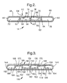
- the fluid pipe 14 is formed with a first side wall 40 and a second side wall 42 which extend in the longitudinal direction substantially parallel to one another, are substantially planar, and which are connected by end walls 44.
- the first wall 40 has first and second portions 46, 48 which are folded inwardly at their free edge to form first, second and third internal walls 50, 52, 54 internally of the side walls 40, 42 and the end walls 44.
- Each of the internal walls 50-54 extends in the longitudinal direction X and contacts the first and second side walls 40, 42.
- the internal walls 50-54 are preferably substantially perpendicular to the side walls 40, 42.
- the first internal wall 50 is defined by a double thickness of the sheet (with one part attached to the first portion 46 of the first side wall 40 and the other part attached to the second portion 48 of the first side wall) and is located intermediate the second and third internal walls 52, 54.
- the first internal wall 50 and the second internal wall 52 are connected by a first planar side portion 56 which contacts a first planar part 58 of the inner surface of the second side wall 42.
- the first internal wall 50 and the third internal wall 54 are connected by a second planar side portion 60 which contacts a second planar part 62 of the inner surface of the second side wall 42.
- a third planar side portion 64 is formed at the edge of the second internal wall 52 adjacent the first portion 46 of the first side wall 40. The third planar side portion 64 extends towards the first internal wall 50 and engages a planar part 66 of the inner surface of the first portion 46 of the first side wall 40.
- a fourth planar side portion 68 is formed at the edge of the third internal wall 54 adjacent the second portion 48 of the first side wall 40. The fourth planar side portion 68 extends towards the first internal wall 50 and engages a planar part 70 of the inner surface of the second portion 48 of the first side wall 40.
- the fluid pipe 14 has four separate fluid channels 72-78 extending through the fluid pipe in the longitudinal direction X.
- the presence of the cladding secures the double thickness of the first internal wall 50 together; secures the first and second planar side portions 56, 60 to the second side wall 42; and secures the third and fourth planar side portions 64, 68 to the first side wall 40; during the brazing process.
- Figure 3 shows a second embodiment of fluid pipe 114 in accordance with the present invention.
- like parts have the same reference numeral as in Figure 2 except with the addition of 100, and the sheet from which the fluid pipe 114 is formed has cladding material on both surfaces.
- the third and fourth planar side portions 164, 168 of the fluid pipe 114 are directed away from the first internal wall 150.
- the fluid pipe 114 further comprises a fourth internal wall 180 connected to the third planar side portion 164 and positioned between the second internal wall 152 and the adjacent end wall 144, and a fifth internal wall 182 connected to the fourth planar side portion 168 and positioned between the third internal wall 154 and the adjacent end wall.
- the fourth and fifth internal walls 180, 182 extend in the longitudinal direction X and extend between the first and second side walls 140, 142.
- a fifth planar side portion 184 is formed at the edge of the fourth internal wall 180 adjacent the second side wall 142.
- the fifth planar side portion 184 extends away the first internal wall 150 and engages a third planar part 186 of the inner surface of the second side wall 142.
- a sixth planar side portion 188 is formed at the edge of the fifth internal wall 182 adjacent the second side wall 142.
- the sixth planar side portion 188 extends away the first internal wall 150 and engages a fourth planar part 190 of the inner surface of the second side wall 142.
- the fifth and sixth planar side portions 184, 188 may be directed towards the first internal wall 150.
- the first internal wall 150 is preferably substantially perpendicular to the first and second side walls 140, 142.
- the second, third, fourth and fifth internal walls 152, 154, 180, 182 extend between the first side wall 140 and the second side wall 142 preferably at a small angle to the perpendicular direction.
- the fluid pipe 114 has six separate fluid channels 172-178, 192, 194 extending through the fluid pipe in the longitudinal direction X.
- the presence of the cladding on both surfaces secures the double thickness of the first internal wall 150 together; secures the first, second, fifth and sixth planar side portions 156, 160, 184, 188 to the second side wall 142; and secures the third and fourth planar side portions 164, 168 to the first side wall 140; during the brazing process.
- Forming the fluid pipes by rolling and folding from a sheet of metallic material allows for thinner pipe walls, reduced costs, and improved assembly operation.
- the use of sheet material with a cladding on at least one surface allows the fluid pipes to be brazed at the same time as the brazing process for the heat exchanger as a whole.
- the present invention provides a strong construction for the fluid pipes which is capable of withstanding high fluid pressures, is more resistant to potential crushing, and has increased stiffness, when compared to known folded fluid tubes, due in part to the planar attachments between the side portions and the side walls.
- the present invention can provide four or more fluid passages with a reduced number of folding operations when compared to EP-A-0302232, and with reduced risk of leakage at the joint with the header tanks.
- the present invention has particular application for heat exchangers used in the air conditioning system or heating system of a motor vehicle, or the radiator used for cooling engine coolant in a motor vehicle.
- the present invention could, however, also be used for heat exchangers having other applications.
Landscapes
- Engineering & Computer Science (AREA)
- Physics & Mathematics (AREA)
- Thermal Sciences (AREA)
- Mechanical Engineering (AREA)
- General Engineering & Computer Science (AREA)
- Heat-Exchange Devices With Radiators And Conduit Assemblies (AREA)
Applications Claiming Priority (2)
| Application Number | Priority Date | Filing Date | Title |
|---|---|---|---|
| GB0016879 | 2000-07-11 | ||
| GB0016879A GB2364770A (en) | 2000-07-11 | 2000-07-11 | Heat exchanger and fluid pipe therefor |
Publications (3)
| Publication Number | Publication Date |
|---|---|
| EP1172623A2 true EP1172623A2 (de) | 2002-01-16 |
| EP1172623A3 EP1172623A3 (de) | 2002-06-26 |
| EP1172623B1 EP1172623B1 (de) | 2004-02-25 |
Family
ID=9895338
Family Applications (1)
| Application Number | Title | Priority Date | Filing Date |
|---|---|---|---|
| EP01202258A Expired - Lifetime EP1172623B1 (de) | 2000-07-11 | 2001-06-12 | Wärmetauscher und Wärmetauscherrohr dafür |
Country Status (4)
| Country | Link |
|---|---|
| US (1) | US6513582B2 (de) |
| EP (1) | EP1172623B1 (de) |
| DE (1) | DE60102104T2 (de) |
| GB (1) | GB2364770A (de) |
Cited By (4)
| Publication number | Priority date | Publication date | Assignee | Title |
|---|---|---|---|---|
| FR2869679A1 (fr) * | 2004-04-29 | 2005-11-04 | Valeo Climatisation Sa | Tubes plies multi-canaux pour echangeur de chaleur, procede d'obtention de tels tubes et echangeur de chaleur muni de ces tubes |
| FR2924793A1 (fr) * | 2007-12-11 | 2009-06-12 | Valeo Systemes Thermiques | Tubes multicanaux pour un echangeur de chaleur brase |
| FR2925665A1 (fr) * | 2007-12-24 | 2009-06-26 | Valeo Systemes Thermiques | Tube plie pour echangeur de chaleur brase,procede de fabrication et echangeur de chaleur |
| EP2388545A3 (de) * | 2010-05-20 | 2018-03-21 | MAHLE International GmbH | Gefaltetes Rohr für einen Verdampfer und Verdampferanordnung damit |
Families Citing this family (20)
| Publication number | Priority date | Publication date | Assignee | Title |
|---|---|---|---|---|
| DE10201511A1 (de) * | 2002-01-17 | 2003-07-31 | Behr Gmbh & Co | Geschweißtes Mehrkammerrohr |
| US20040206482A1 (en) * | 2003-04-17 | 2004-10-21 | Joong-Cheol Bang | Integrated heat exchanger for vehicle and method for manufacturing the same |
| DE10328001A1 (de) | 2003-06-21 | 2005-01-05 | Modine Manufacturing Co., Racine | Flaches Wärmetauscherrohr |
| US7032808B2 (en) * | 2003-10-06 | 2006-04-25 | Outokumu Oyj | Thermal spray application of brazing material for manufacture of heat transfer devices |
| US20060230617A1 (en) * | 2005-04-13 | 2006-10-19 | Kent Scott E | Fabricated, brazed metal heat exchanger tube manufacture |
| FR2902831B1 (fr) * | 2006-06-27 | 2010-10-22 | Airbus France | Turboreacteur pour aeronef |
| WO2008064199A1 (en) | 2006-11-22 | 2008-05-29 | Johnson Controls Technology Company | Multichannel evaporator with flow separating manifold |
| JP4297177B2 (ja) * | 2007-04-03 | 2009-07-15 | 株式会社デンソー | 熱交換器用チューブ |
| WO2009018150A1 (en) * | 2007-07-27 | 2009-02-05 | Johnson Controls Technology Company | Multichannel heat exchanger |
| DE102007039292A1 (de) * | 2007-08-20 | 2009-02-26 | Behr Gmbh & Co. Kg | Mehrkammer-Flachrohr, Wärmetauscher und Verwendung eines Wärmetauschers |
| FR2923002B1 (fr) * | 2007-10-31 | 2015-12-11 | Valeo Systemes Thermiques | Tube pour echangeur thermique |
| DE102008007612A1 (de) * | 2008-02-04 | 2009-08-06 | Behr Gmbh & Co. Kg | Mehrkammer-Flachrohr, Wärmetauscher und Verwendung eines Wärmetauschers |
| US20100006276A1 (en) * | 2008-07-11 | 2010-01-14 | Johnson Controls Technology Company | Multichannel Heat Exchanger |
| US8234881B2 (en) * | 2008-08-28 | 2012-08-07 | Johnson Controls Technology Company | Multichannel heat exchanger with dissimilar flow |
| US8439104B2 (en) * | 2009-10-16 | 2013-05-14 | Johnson Controls Technology Company | Multichannel heat exchanger with improved flow distribution |
| KR101936243B1 (ko) * | 2012-04-26 | 2019-01-08 | 엘지전자 주식회사 | 열교환기 |
| GB2509762B (en) * | 2013-01-14 | 2015-02-04 | Halla Visteon Climate Control | Tube for Heat Exchanger |
| CN104792210A (zh) * | 2014-01-16 | 2015-07-22 | 泰安鼎鑫冷却器有限公司 | 三部件组合散热管 |
| US10801781B2 (en) * | 2018-10-17 | 2020-10-13 | Hanon Systems | Compliant b-tube for radiator applications |
| US20200271393A1 (en) * | 2019-02-27 | 2020-08-27 | GM Global Technology Operations LLC | Heat exchanger tube |
Citations (2)
| Publication number | Priority date | Publication date | Assignee | Title |
|---|---|---|---|---|
| EP0302232A1 (de) | 1987-08-01 | 1989-02-08 | Behr GmbH & Co. | Flachrohr für einen Wärmetauscher |
| EP0646231A1 (de) | 1992-06-24 | 1995-04-05 | Llanelli Radiators Ltd | Wärmtetauscherrohre. |
Family Cites Families (7)
| Publication number | Priority date | Publication date | Assignee | Title |
|---|---|---|---|---|
| FR2716529B1 (fr) * | 1994-02-18 | 1996-04-26 | Valeo Thermique Habitacle | Tube plat résistant à l'écrasement pour échangeur de chaleur. |
| FR2756371B1 (fr) * | 1996-11-25 | 1999-01-29 | Valeo Thermique Moteur Sa | Tube plat a canaux multiples pour echangeur de chaleur |
| FR2757258B1 (fr) * | 1996-12-12 | 1999-03-05 | Valeo Equip Electr Moteur | Tube plat a plusieurs canaux pour echangeur de chaleur |
| JPH10193085A (ja) * | 1997-01-13 | 1998-07-28 | Shinko Alcoa Yuso Kizai Kk | 熱交換器用偏平管 |
| US5956846A (en) * | 1997-03-21 | 1999-09-28 | Livernois Research & Development Co. | Method and apparatus for controlled atmosphere brazing of unwelded tubes |
| GB2324145A (en) * | 1997-04-07 | 1998-10-14 | Rollsec Ltd | Heat exchanger element |
| JP2000158070A (ja) * | 1998-12-02 | 2000-06-13 | Toyota Motor Corp | 熱交換器用チューブ |
-
2000
- 2000-07-11 GB GB0016879A patent/GB2364770A/en not_active Withdrawn
-
2001
- 2001-06-12 EP EP01202258A patent/EP1172623B1/de not_active Expired - Lifetime
- 2001-06-12 DE DE60102104T patent/DE60102104T2/de not_active Expired - Lifetime
- 2001-06-14 US US09/883,143 patent/US6513582B2/en not_active Expired - Lifetime
Patent Citations (2)
| Publication number | Priority date | Publication date | Assignee | Title |
|---|---|---|---|---|
| EP0302232A1 (de) | 1987-08-01 | 1989-02-08 | Behr GmbH & Co. | Flachrohr für einen Wärmetauscher |
| EP0646231A1 (de) | 1992-06-24 | 1995-04-05 | Llanelli Radiators Ltd | Wärmtetauscherrohre. |
Cited By (4)
| Publication number | Priority date | Publication date | Assignee | Title |
|---|---|---|---|---|
| FR2869679A1 (fr) * | 2004-04-29 | 2005-11-04 | Valeo Climatisation Sa | Tubes plies multi-canaux pour echangeur de chaleur, procede d'obtention de tels tubes et echangeur de chaleur muni de ces tubes |
| FR2924793A1 (fr) * | 2007-12-11 | 2009-06-12 | Valeo Systemes Thermiques | Tubes multicanaux pour un echangeur de chaleur brase |
| FR2925665A1 (fr) * | 2007-12-24 | 2009-06-26 | Valeo Systemes Thermiques | Tube plie pour echangeur de chaleur brase,procede de fabrication et echangeur de chaleur |
| EP2388545A3 (de) * | 2010-05-20 | 2018-03-21 | MAHLE International GmbH | Gefaltetes Rohr für einen Verdampfer und Verdampferanordnung damit |
Also Published As
| Publication number | Publication date |
|---|---|
| DE60102104T2 (de) | 2004-07-22 |
| DE60102104D1 (de) | 2004-04-01 |
| US20020005281A1 (en) | 2002-01-17 |
| EP1172623B1 (de) | 2004-02-25 |
| US6513582B2 (en) | 2003-02-04 |
| EP1172623A3 (de) | 2002-06-26 |
| GB2364770A (en) | 2002-02-06 |
| GB0016879D0 (en) | 2000-08-30 |
Similar Documents
| Publication | Publication Date | Title |
|---|---|---|
| US6513582B2 (en) | Heat exchanger and fluid pipe therefor | |
| CN101548149B (zh) | 用于冷凝器和/或蒸发器的焊接平管 | |
| US20050061489A1 (en) | Integrated multi-function return tube for combo heat exchangers | |
| US20080000626A1 (en) | Heat exchanger | |
| US11209212B2 (en) | High pressure capable liquid to refrigerant heat exchanger | |
| US20170198975A1 (en) | Heat Exchanger Construction | |
| JP3829494B2 (ja) | 熱交換器 | |
| US20020023730A1 (en) | Compact heat exchanger for a compact cooling system | |
| US5246066A (en) | One piece extruded tank | |
| US7174953B2 (en) | Stacking-type, multi-flow, heat exchanger | |
| JPH11351777A (ja) | 熱交換器用扁平伝熱管 | |
| US6601644B2 (en) | Corrosion preventing layer forming method | |
| CN100520267C (zh) | 用于换热器的管型面 | |
| EP1962036A1 (de) | Wärmetauscher mit sammelbehälter | |
| JP3674120B2 (ja) | 熱交換器 | |
| US5794692A (en) | Header and tank construction for a heat exchanger | |
| EP0632246B1 (de) | Wärmetauscher | |
| US7552756B2 (en) | Brazed aluminum radiator with PTO section and method of making the same | |
| JP3317672B2 (ja) | 熱交換器 | |
| US5346003A (en) | Face plumbed condenser for automotive air conditioner | |
| US20080105415A1 (en) | Chamber For Holding A Fluid For A Heat Exchanger, Heat Exchanger, More Particularly For A Heat Exchange Unit, And A Heat Exchange Unit, In Particular In The Form Of A Monoblock | |
| JP2831578B2 (ja) | ブラケットを備えた熱交換器の製造方法 | |
| JP2000304489A (ja) | 熱交換器及び放熱器 | |
| JPH0914886A (ja) | 複式熱交換器 | |
| JP4058824B2 (ja) | 複式熱交換器 |
Legal Events
| Date | Code | Title | Description |
|---|---|---|---|
| PUAI | Public reference made under article 153(3) epc to a published international application that has entered the european phase |
Free format text: ORIGINAL CODE: 0009012 |
|
| AK | Designated contracting states |
Kind code of ref document: A2 Designated state(s): AT BE CH CY DE DK ES FI FR GB GR IE IT LI LU MC NL PT SE TR |
|
| AX | Request for extension of the european patent |
Free format text: AL;LT;LV;MK;RO;SI |
|
| PUAL | Search report despatched |
Free format text: ORIGINAL CODE: 0009013 |
|
| AK | Designated contracting states |
Kind code of ref document: A3 Designated state(s): AT BE CH CY DE DK ES FI FR GB GR IE IT LI LU MC NL PT SE TR |
|
| AX | Request for extension of the european patent |
Free format text: AL;LT;LV;MK;RO;SI |
|
| 17P | Request for examination filed |
Effective date: 20021227 |
|
| AKX | Designation fees paid |
Designated state(s): DE FR GB IT |
|
| 17Q | First examination report despatched |
Effective date: 20030324 |
|
| GRAP | Despatch of communication of intention to grant a patent |
Free format text: ORIGINAL CODE: EPIDOSNIGR1 |
|
| GRAS | Grant fee paid |
Free format text: ORIGINAL CODE: EPIDOSNIGR3 |
|
| GRAA | (expected) grant |
Free format text: ORIGINAL CODE: 0009210 |
|
| AK | Designated contracting states |
Kind code of ref document: B1 Designated state(s): DE FR GB IT |
|
| REG | Reference to a national code |
Ref country code: GB Ref legal event code: FG4D |
|
| REG | Reference to a national code |
Ref country code: IE Ref legal event code: FG4D |
|
| REF | Corresponds to: |
Ref document number: 60102104 Country of ref document: DE Date of ref document: 20040401 Kind code of ref document: P |
|
| ET | Fr: translation filed | ||
| PLBE | No opposition filed within time limit |
Free format text: ORIGINAL CODE: 0009261 |
|
| STAA | Information on the status of an ep patent application or granted ep patent |
Free format text: STATUS: NO OPPOSITION FILED WITHIN TIME LIMIT |
|
| 26N | No opposition filed |
Effective date: 20041126 |
|
| REG | Reference to a national code |
Ref country code: IE Ref legal event code: MM4A |
|
| REG | Reference to a national code |
Ref country code: DE Ref legal event code: R082 Ref document number: 60102104 Country of ref document: DE Representative=s name: BRP RENAUD UND PARTNER MBB RECHTSANWAELTE PATE, DE Ref country code: DE Ref legal event code: R082 Ref document number: 60102104 Country of ref document: DE Representative=s name: BRP RENAUD UND PARTNER MBB, DE Ref country code: DE Ref legal event code: R081 Ref document number: 60102104 Country of ref document: DE Owner name: MAHLE INTERNATIONAL GMBH, DE Free format text: FORMER OWNER: DELPHI TECHNOLOGIES, INC., TROY, MICH., US |
|
| REG | Reference to a national code |
Ref country code: FR Ref legal event code: PLFP Year of fee payment: 16 |
|
| REG | Reference to a national code |
Ref country code: GB Ref legal event code: 732E Free format text: REGISTERED BETWEEN 20161208 AND 20161214 |
|
| REG | Reference to a national code |
Ref country code: FR Ref legal event code: PLFP Year of fee payment: 17 |
|
| REG | Reference to a national code |
Ref country code: FR Ref legal event code: TP Owner name: MAHLE INTERNATIONAL GMBH, DE Effective date: 20180103 |
|
| REG | Reference to a national code |
Ref country code: FR Ref legal event code: PLFP Year of fee payment: 18 |
|
| PGFP | Annual fee paid to national office [announced via postgrant information from national office to epo] |
Ref country code: FR Payment date: 20200626 Year of fee payment: 20 |
|
| PGFP | Annual fee paid to national office [announced via postgrant information from national office to epo] |
Ref country code: IT Payment date: 20200618 Year of fee payment: 20 Ref country code: GB Payment date: 20200629 Year of fee payment: 20 |
|
| PGFP | Annual fee paid to national office [announced via postgrant information from national office to epo] |
Ref country code: DE Payment date: 20200827 Year of fee payment: 20 |
|
| REG | Reference to a national code |
Ref country code: DE Ref legal event code: R071 Ref document number: 60102104 Country of ref document: DE |
|
| REG | Reference to a national code |
Ref country code: GB Ref legal event code: PE20 Expiry date: 20210611 |
|
| PG25 | Lapsed in a contracting state [announced via postgrant information from national office to epo] |
Ref country code: GB Free format text: LAPSE BECAUSE OF EXPIRATION OF PROTECTION Effective date: 20210611 |