EP1174639A2 - Getriebe, insbesondere für einen Roboter - Google Patents
Getriebe, insbesondere für einen Roboter Download PDFInfo
- Publication number
- EP1174639A2 EP1174639A2 EP01113809A EP01113809A EP1174639A2 EP 1174639 A2 EP1174639 A2 EP 1174639A2 EP 01113809 A EP01113809 A EP 01113809A EP 01113809 A EP01113809 A EP 01113809A EP 1174639 A2 EP1174639 A2 EP 1174639A2
- Authority
- EP
- European Patent Office
- Prior art keywords
- shaft
- gear
- transmission
- transmission according
- rotation
- Prior art date
- Legal status (The legal status is an assumption and is not a legal conclusion. Google has not performed a legal analysis and makes no representation as to the accuracy of the status listed.)
- Withdrawn
Links
- 230000005540 biological transmission Effects 0.000 title claims description 77
- 238000012806 monitoring device Methods 0.000 claims description 7
- 230000003287 optical effect Effects 0.000 claims description 3
- 230000000149 penetrating effect Effects 0.000 description 6
- 230000008878 coupling Effects 0.000 description 4
- 238000010168 coupling process Methods 0.000 description 4
- 238000005859 coupling reaction Methods 0.000 description 4
- 238000012544 monitoring process Methods 0.000 description 3
- 210000001520 comb Anatomy 0.000 description 1
- 238000011109 contamination Methods 0.000 description 1
- 230000010354 integration Effects 0.000 description 1
- 230000009467 reduction Effects 0.000 description 1
- 238000005096 rolling process Methods 0.000 description 1
Images



Classifications
-
- F—MECHANICAL ENGINEERING; LIGHTING; HEATING; WEAPONS; BLASTING
- F16—ENGINEERING ELEMENTS AND UNITS; GENERAL MEASURES FOR PRODUCING AND MAINTAINING EFFECTIVE FUNCTIONING OF MACHINES OR INSTALLATIONS; THERMAL INSULATION IN GENERAL
- F16H—GEARING
- F16H1/00—Toothed gearings for conveying rotary motion
- F16H1/02—Toothed gearings for conveying rotary motion without gears having orbital motion
- F16H1/20—Toothed gearings for conveying rotary motion without gears having orbital motion involving more than two intermeshing members
- F16H1/22—Toothed gearings for conveying rotary motion without gears having orbital motion involving more than two intermeshing members with a plurality of driving or driven shafts; with arrangements for dividing torque between two or more intermediate shafts
-
- Y—GENERAL TAGGING OF NEW TECHNOLOGICAL DEVELOPMENTS; GENERAL TAGGING OF CROSS-SECTIONAL TECHNOLOGIES SPANNING OVER SEVERAL SECTIONS OF THE IPC; TECHNICAL SUBJECTS COVERED BY FORMER USPC CROSS-REFERENCE ART COLLECTIONS [XRACs] AND DIGESTS
- Y10—TECHNICAL SUBJECTS COVERED BY FORMER USPC
- Y10T—TECHNICAL SUBJECTS COVERED BY FORMER US CLASSIFICATION
- Y10T74/00—Machine element or mechanism
- Y10T74/19—Gearing
- Y10T74/19642—Directly cooperating gears
-
- Y—GENERAL TAGGING OF NEW TECHNOLOGICAL DEVELOPMENTS; GENERAL TAGGING OF CROSS-SECTIONAL TECHNOLOGIES SPANNING OVER SEVERAL SECTIONS OF THE IPC; TECHNICAL SUBJECTS COVERED BY FORMER USPC CROSS-REFERENCE ART COLLECTIONS [XRACs] AND DIGESTS
- Y10—TECHNICAL SUBJECTS COVERED BY FORMER USPC
- Y10T—TECHNICAL SUBJECTS COVERED BY FORMER US CLASSIFICATION
- Y10T74/00—Machine element or mechanism
- Y10T74/19—Gearing
- Y10T74/19642—Directly cooperating gears
- Y10T74/19647—Parallel axes or shafts
-
- Y—GENERAL TAGGING OF NEW TECHNOLOGICAL DEVELOPMENTS; GENERAL TAGGING OF CROSS-SECTIONAL TECHNOLOGIES SPANNING OVER SEVERAL SECTIONS OF THE IPC; TECHNICAL SUBJECTS COVERED BY FORMER USPC CROSS-REFERENCE ART COLLECTIONS [XRACs] AND DIGESTS
- Y10—TECHNICAL SUBJECTS COVERED BY FORMER USPC
- Y10T—TECHNICAL SUBJECTS COVERED BY FORMER US CLASSIFICATION
- Y10T74/00—Machine element or mechanism
- Y10T74/19—Gearing
- Y10T74/19642—Directly cooperating gears
- Y10T74/19679—Spur
- Y10T74/19684—Motor and gearing
-
- Y—GENERAL TAGGING OF NEW TECHNOLOGICAL DEVELOPMENTS; GENERAL TAGGING OF CROSS-SECTIONAL TECHNOLOGIES SPANNING OVER SEVERAL SECTIONS OF THE IPC; TECHNICAL SUBJECTS COVERED BY FORMER USPC CROSS-REFERENCE ART COLLECTIONS [XRACs] AND DIGESTS
- Y10—TECHNICAL SUBJECTS COVERED BY FORMER USPC
- Y10T—TECHNICAL SUBJECTS COVERED BY FORMER US CLASSIFICATION
- Y10T74/00—Machine element or mechanism
- Y10T74/20—Control lever and linkage systems
- Y10T74/20207—Multiple controlling elements for single controlled element
- Y10T74/20305—Robotic arm
- Y10T74/20329—Joint between elements
-
- Y—GENERAL TAGGING OF NEW TECHNOLOGICAL DEVELOPMENTS; GENERAL TAGGING OF CROSS-SECTIONAL TECHNOLOGIES SPANNING OVER SEVERAL SECTIONS OF THE IPC; TECHNICAL SUBJECTS COVERED BY FORMER USPC CROSS-REFERENCE ART COLLECTIONS [XRACs] AND DIGESTS
- Y10—TECHNICAL SUBJECTS COVERED BY FORMER USPC
- Y10T—TECHNICAL SUBJECTS COVERED BY FORMER US CLASSIFICATION
- Y10T74/00—Machine element or mechanism
- Y10T74/20—Control lever and linkage systems
- Y10T74/20207—Multiple controlling elements for single controlled element
- Y10T74/20305—Robotic arm
- Y10T74/20329—Joint between elements
- Y10T74/20335—Wrist
Definitions
- the invention relates to a transmission, in particular for a Robot, with a drive shaft and at least two relative to this and parts rotatable relative to each other, wherein a movement of one part on the other Part facing away is removable, and one with at least robot equipped with such a transmission.
- Multi-axis robots are e.g. in the form of industrial robots known and serve the automatic execution of transport and operations. They usually have one a frame arranged to rotate about a base axis Carousel and a structure placed on the carousel with a robotic arm that can be swiveled around several axes.
- gearboxes For swiveling the axis of rotation of the robot towards one another, e.g. for rotating the carousel with respect to the stationary one Frame, are gearboxes with a drive shaft and at least two rotatable relative to this and relative to each other Parts like two half shells or a gear shaft and a gear housing are provided, on each of which one the robot parts that can be pivoted about the respective robot axis is set.
- the movement of one part, e.g. of the gearbox must therefore be on the other Part, e.g. the gear shaft, side facing away on.
- the drive shaft is usually with a drive motor in operative connection.
- sensor devices are required that record and monitor the angular positions of the robot axes and limit if necessary, so that e.g. one with one Target course comparable actual course of the angular position the robot axes are preserved and the actual values if necessary can be adapted to the target values.
- the invention has for its object a transmission type mentioned in a simple and inexpensive way to further train that one in the transmission integrated arrangement of additional devices, e.g. B. one Sensor device or a device for loading one of the relatively rotatable parts of the transmission with a torque, e.g. an auxiliary motor, is possible.
- additional devices e.g. B. one Sensor device or a device for loading one of the relatively rotatable parts of the transmission with a torque, e.g. an auxiliary motor, is possible.
- this object is achieved in a transmission initially mentioned type in that at least one the rotatable parts are connected to it in a rotationally fixed manner Has shaft that protrudes at least to the other part.
- additional devices such as sensor devices, movement limiting devices, Auxiliary motors or the like.
- the movement of the one equipped with the additional shaft consequently, a rotatable part of the gearbox is both on the other, rotatable relative to this Part of the transmission facing away, as is the case with conventional Gear is known, as well as at its the other Part facing side on the protruding part Removable shaft, which in particular detects the relative movement of the two gear parts rotatable relative to each other allows.
- a preferred embodiment provides that the one Partly arranged shaft drive one in and / or on the other part arranged sensor device, the Sensor device, for example, as a monitoring device to record and / or limit the rotation parameters can be trained.
- the transmission is in the case of such in the Gear integrated sensor device a mechanical Damage or contamination of the sensor device as far as possible avoided and consequently continuous acquisition and monitoring the angular position of the axis of rotation and, if necessary, a limitation of their angle of rotation is ensured.
- the integration of the sensor device in the Transmission also results in a more compact structure of the Robot, with an undesirable restriction of mobility the axes of rotation of the robot through the sensor device is excluded.
- the sensor device a stub in a recording has and the angle of rotation between the shaft end and recording detected.
- Such sensor devices are known per se. They are generally essentially coaxial with the Axis of rotation of the robot arranged and have, for example on the face of the shaft end in the receptacle arranged optical, magnetic or electromagnetic Encoder on the angular position of each Detect and / or monitor the axis of rotation.
- the angle of rotation of one in the recording arranged device such as a Diode in connection with a photo receiver.
- the sensor device While recording the sensor device with advantage one part of the gearbox is the stub shaft the sensor device preferably with the the other part of the transmission arranged to the one Part protruding or penetrating this shaft rotatably connected.
- a part of the gearbox according to Art a gear housing and the other part like a Gear shaft formed, so the inclusion of the sensor device for example in the area of the gearbox facing end of the gear shaft and here arranged essentially coaxially to the axis of rotation of the robot be while the stub shaft on to the gearbox protruding shaft of the gear shaft sits.
- the recording can either on the gear shaft facing Inside or on the outside facing away from the gear shaft be arranged of the gear housing, the shaft stub rotatably connected to the shaft of the gear shaft in the latter case penetrates the gear housing.
- the senor device rotatably connected to the gear shaft during the Stub shaft on the protruding to the gear shaft, this e.g. penetrating shaft of the gear housing arranged is.
- the monitoring device can thus e.g. in the area the gearbox housing facing or the this remote end of the gear shaft arranged his.
- optical, electrical, electromagnetic or magnetic Monitoring device in particular a resolver, provided, for example with a torque compensation for the respective axis of rotation or with a control device to adapt the movement data of the robot in connection can stand.
- Another preferred embodiment provides that the part arranged shaft with a torque can be acted upon, for example by means of an auxiliary motor can happen.
- the drive shaft is preferably a high-speed side Output shaft of a drive motor or with such connectable so that the rotatable parts of the gearbox with with respect to the speed of the drive shaft lower speed are movable.
- the one arranged on the one rotatable part of the transmission the shaft protruding to the other part is expediently coaxial to the axis of rotation of at least one of the rotatable parts of the transmission arranged, preferably both relative to each other rotatable parts of the transmission arranged coaxially are.
- the transmission is preferably a step-up gear, in particular Helical, bevel, worm or epicyclic gear, e.g. a planetary gear.
- the gearbox be a harmonic drive gearbox is.
- Harmonic drive gears include one Outer ring with internal teeth, into which an external toothing of a flexible tube engages.
- the diameter of the pipe is slightly less than the width of the outer ring, so that a tooth engagement only takes place as soon as the pipe is through an oval or elliptical rotating inside Rotating body is deformed elliptically. Since the number of Slightly differentiate teeth from tube (Flexspline) and outer ring, this turns in particular on the output side Pipe slowly when the rotating body, in particular on the drive side rotates.
- gears are very low backlash and achieve high reductions. They have been in the past widely used in robots due to their high precision used. They are currently due to their disadvantages (limited robustness, skipping teeth at high Load, low backward efficiency) largely from other gears have been displaced so that their use today mainly on small robots and hand axes limited.
- the drive motor can be central, eccentric or under a finite angle, especially at a right angle Angle with respect to the axis of rotation of at least one of the parts of the gearbox.
- the invention also relates to one with at least one a robot equipped with a gear of the aforementioned type.
- Fig. 1 is a gear 1, in particular for a robot (not shown), with a drive shaft 7 and two parts 3, 4 rotatable relative to this and relative to each other about a common axis of rotation 2 - here with gear shaft 3 and gear housing 4 - with different diameters D 3 , D 4 are shown.
- the movement of part 3 can be removed in a known manner on its side 3b facing away from part 4 and correspondingly the movement of part 4 - relative to part 3 and also to drive shaft 7 - on its side 4b facing away from part 3.
- the part 3 has a shaft 15 protruding toward the part 4 - and in the embodiment shown passing through the part 4 - so that the movement of the part 3 by means of the shaft 15 connected to it also on the side 4b of the part 3 facing the part 3 Part 4 is removable.
- the shaft 15 can, for example, drive a sensor device arranged in or on the part 4, such as a monitoring device (not shown) for detecting and / or limiting the angle of rotation between the parts 3, 4 or for arranging an auxiliary motor (not shown) or the like serve.
- the drive shaft 7 is in particular a high-speed side Drive shaft of a drive motor (not shown) or connectable with one such that the parts 3, 4 with lower with respect to the speed of the drive shaft 7 Speed are movable.
- the from the side of part 4 am Transmission shaft 7 attacking gear can of course also coaxial to the axis of rotation 2 of the transmission 1 and / or attack from part 3.
- FIG. 3 shows a gear 1 with two parts 3, 4 of approximately the same diameter D 3 , D 4 which can be rotated relative to one another, a shaft 15 arranged on the part 3 passing through the part 4 to its side 4b facing away from the part 3. 3, a drive shaft 7, which is arranged eccentrically with respect to its axis of rotation 2 and engages from the part 4 penetrated by the shaft 15, is provided for the drive shaft in the transmission 1 shown in FIG. 4, of which the shaft 15 having part 4 attacking and also arranged eccentrically to its axis of rotation 2.
- the transmission shaft and housing cannot be distinguished and the designation is assigned only by definition based on the fact that, as a rule, the motor housing of the drive motor is connected to the transmission housing in a rotationally fixed manner, which is therefore as such can be designated.
- the transmission 1 according to FIG. 5 differs from the transmission shown in FIG. 3 in that the part 4 in the manner of a half-shell or a transmission housing and the part 3 in the manner of a transmission shaft 3 accommodated by the transmission housing 3 with respect to the diameter D 3 of the gear housing 3 is formed smaller diameter D 4 .
- the drive shaft 7 is, for example, operatively connected to the transmission housing 4 and arranged eccentrically to the axis of rotation 2 of the transmission 1.
- FIG. 6 shows a section through a transmission 1 with a Part 3 designed in the manner of a gear shaft, which relative to one designed in the manner of a gear housing Part 4 is rotatable.
- the movement of one of the parts (3, 4) is on the other part (4, 3) opposite side (3b, 4b) removable.
- As drive shaft 7 an output shaft is used on the one of the transmission shaft 3 opposite side 4b of the gear housing 4 eccentrically to Axis of rotation 2 of the transmission 1 arranged drive motor 6.
- the motor housing is non-rotatable with part 4 of the gearbox the gearbox.
- the gear shaft 3 is by means of rolling bearings, e.g. ball bearings 5, stored in the gear housing 4.
- the gear housing 4 has a rotationally fixed connected with this, penetrating the transmission shaft 3 Wave 15 on.
- To transmit the torque of the particular high-speed drive shaft 7 is one on this seated gear 16 provided with a on the gear housing 4 rotatably mounted gear 17 which combs again with a rotationally fixed with the gear shaft 3 connected gear 18 is engaged.
- the gears 16, 17, 18 enable a translation of the torque of the drive motor 6 and bridge the eccentric arrangement its drive shaft 7 with respect to the gear axis 2.
- the transmission 1 shown in FIG. 7 has a first part 3 in the form of a gear shaft. This is in another Part 4 in the form of a gear housing by means of bearings 5 coaxially mounted and rotatable relative to this.
- the drive motor 6 engages with its drive shaft 7 for pivoting the transmission shaft 3 about an axis of rotation 2 a multi-axis robot (not shown) on this.
- the gearbox 4 can e.g. stationary on a frame Robot base may be arranged while the gear shaft 3 carrying a carousel with the robot. In this case acts axis of rotation 2 is about the A1 axis of the robot.
- the gear shaft 3 can be mounted in the gear housing 4 can also be just a bearing 5. Also one can Storage outside of the gearbox on the on the gearbox 4 and the gear shaft 3 arranged robot components (not shown) may be provided.
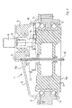
- a sensor device 10 For recording and monitoring the angle of rotation of the gear shaft 3 with respect to the transmission housing 4 is a sensor device 10 is provided, which is coaxial to the axis of rotation 2 of the Robot is arranged.
- the sensor device 10 comprises one guided in a sensor housing or a receptacle 13 Stub shaft 12, which has a coupling 11 with a to the gear housing 4 projecting shaft 15 of the gear shaft 3 is rotatably connected. It records the angle of rotation between shaft end 12 and receptacle 13.
- the receptacle 13 the sensor device 10 is on the gear shaft 3 facing away Outside 4b of e.g. stationary gear housing 4 arranged, the via the coupling 11 with the Gear shaft 3 connected stub shaft 12 in the gear housing 4 engages.
- the clutch 11 can for example be designed as a clamping, bellows coupling or the like.
- the drive motor 6 seated on the gear shaft 3 is in the embodiment shown arranged centrally to the axis of rotation 2.
- the sensor device 10 is, for example, a monitoring device to record and / or monitor the Angle of rotation between the gear housing 4 and the gear shaft 3 trained and stands e.g. with a moment compensation for the axis of rotation 2 of the robot in connection (not shown).
- gear 9 is a gear 1 with a by means of bearings 5 in a gearbox 4 mounted gear shaft 3 shown.
- To drive the gear shaft 3 is a reference their axis of rotation 2 eccentrically arranged on the gear housing 4
- Drive motor 6 with the gearbox on one 4 penetrating drive shaft 7 seated gear 8 provided, which with a rotationally fixed with the gear shaft 3 connected gear 9 meshes.
- To capture and monitoring the angle of rotation of the transmission shaft 3 with respect e.g. stationary gear housing 4 is in turn a sensor device arranged coaxially to the axis of rotation 2 of the robot 10 is provided, which corresponds to the sensor device 10 as shown in FIGS. 7 and 8 and the Angle of rotation between the shaft stub guided in the receptacle 13 12 and the recording 13 recorded.
- the integrated in the transmission 1 Sensor device 10 in this case for reasons of space Area of the end face 4b facing away from the gear housing 4 the gear shaft 3 arranged.
- the receptacle 13 of the sensor device 10 is non-rotatably on the gear shaft via a sleeve 14 3 set during the stub 12 over a clutch 11 with a the transmission shaft 3 to their Transmission housing 3 side 3b penetrating through Shaft 15 of the gear housing 4 is connected.
- the gear housing can be on the gear shaft 3 4 to its side facing away from the gear shaft 3 penetrating shaft (not shown) may be provided on the the sensor device is arranged with respect to the transmission housing 4 can be.
Landscapes
- Engineering & Computer Science (AREA)
- General Engineering & Computer Science (AREA)
- Mechanical Engineering (AREA)
- Manipulator (AREA)
- Transmission Devices (AREA)
- Retarders (AREA)
Abstract
Description
- Fig.1
- eine schematische Seitenansicht eines Getriebes;
- Fig.2
- eine schematische Seitenansicht einer Ausführungsvariante des Getriebes gemäß Fig. 1;
- Fig.3
- eine schematische Schnittansicht einer anderen Ausführungsform eines Getriebes;
- Fig.4
- eine schematische Schnittansicht einer Ausführungsvariante des Getriebes gemäß Fig. 3;
- Fig.5
- eine schematische Schnittansicht eines Getriebes mit relativ zueinander drehbaren Teilen in Form eines Getriebegehäuses und einer Getriebewelle;
- Fig.6
- eine Schnittansicht einer Ausführungsvariante des Getriebes gemäß Fig. 5;
- Fig.7
- eine schematische Schnittansicht eines Getriebes mit relativ zueinander drehbaren Teilen in Form eines Getriebegehäuses und einer Getriebewelle mit Sensoreinrichtung;
- Fig.8
- eine schematische Schnittansicht einer Ausführungsvariante des Getriebes gemäß Fig. 7 und
- Fig.9
- eine schematische Schnittansicht einer anderen Ausführungsform eines Getriebes mit integrierter Sensoreinrichtung.
Claims (24)
- Getriebe (1), insbesondere für einen Roboter, mit einer Antriebswelle (7) und wenigstens zwei relativ zu dieser und relativ zueinander drehbaren Teilen (3, 4), wobei eine Bewegung des einen Teils (3, 4) auf seiner dem anderen Teil (4, 3) abgewandten Seite (3b, 4b) abnehmbar ist, dadurch gekennzeichnet, dass wenigstens eines der drehbaren Teile (3, 4) eine drehfest mit ihm verbundene Welle (15) aufweist, die zumindest zu dem anderen Teil (4, 3) hinragt.
- Getriebe nach Anspruch 1, dadurch gekennzeichnet, dass die an dem einen Teil (3, 4) angeordnete Welle (15) das andere Teil (4, 3) zu seiner dem einen Teil (3, 4) abgewandten Seite (4b, 3b) hin durchsetzt.
- Getriebe nach Anspruch 1 oder 2, dadurch gekennzeichnet, dass die an dem einen Teil (3,4) angeordnete Welle (15) Antrieb einer in und/oder an dem anderen Teil (4,3) angeordneten Sensoreinrichtung (10) ist.
- Getriebe nach Anspruch 3, dadurch gekennzeichnet, dass die Sensoreinrichtung (10) eine Überwachungseinrichtung zur Erfassung und/oder Begrenzung der Drehparameter ist.
- Getriebe nach Anspruch 3 oder 4, dadurch gekennzeichnet, dass die Sensoreinrichtung (10) einen in einer Aufnahme (13) geführten Wellenstummel (12) aufweist und den Drehwinkel zwischen Wellenstummel (12) und Aufnahme (13) erfasst.
- Roboter nach Anspruch 5, dadurch gekennzeichnet, dass die Aufnahme (13) der Sensoreinrichtung (10) an dem einen Teil (3, 4) angeordnet und der Wellenstummel (12) mit der am anderen Teil (4, 3) angeordneten Welle (15) drehfest verbunden ist.
- Roboter nach einem der Ansprüche 3 bis 6, dadurch gekennzeichnet, dass eine optische Sensoreinrichtung (10) vorgesehen ist.
- Roboter nach einem der Ansprüche 3 bis 6, dadurch gekennzeichnet, dass eine magnetische Sensoreinrichtung (10), insbesondere ein Resolver, vorgesehen ist.
- Roboter nach einem der Ansprüche 3 bis 6, dadurch gekennzeichnet, dass eine elektrische oder elektromagnetische Sensoreinrichtung (10) vorgesehen ist.
- Roboter nach einem der Ansprüche 3 bis 9, dadurch gekennzeichnet, dass ein mit der Sensoreinrichtung (10) in Verbindung stehender Momentenausgleich für die jeweilige Drehachse (2) des Roboters vorgesehen ist.
- Getriebe nach einem der Ansprüche 1 bis 10, dadurch gekennzeichnet, dass die an dem einen Teil (3, 4) angeordnete Welle (15) mit einem Drehmoment beaufschlagbar ist.
- Getriebe nach Anspruch 11, dadurch gekennzeichnet, dass an der Welle (15) ein Hilfsmotor angeordnet ist.
- Getriebe nach einem der Ansprüche 1 bis 12, dadurch gekennzeichnet, dass die Antriebswelle (7) eine hochdrehzahlseitige Abtriebswelle eines Antriebsmotors (6) oder mit einer solchen verbindbar ist.
- Getriebe nach einem der Ansprüche 1 bis 13, dadurch gekennzeichnet, dass die drehbaren Teile (3, 4) mit bezüglich der Drehzahl der Antriebswelle (7) niedrigerer Drehzahl bewegbar sind.
- Getriebe nach einem der Ansprüche 1 bis 14, dadurch gekennzeichnet, dass die Welle (15) koaxial zur Drehachse (2) wenigstens eines der Teile (3, 4) angeordnet ist.
- Getriebe nach einem der Ansprüche 1 bis 15, dadurch gekennzeichnet, dass die Teile (3, 4) koaxial angeordnet sind.
- Getriebe nach einem der Ansprüche 1 bis 16, dadurch gekennzeichnet, dass das Getriebe (1) ein insbesondere hochuntersetzendes Stirnrad-, Kegelrad-, Schneckenrad- oder Umlaufgetriebe ist.
- Getriebe nach einem der Ansprüche 1 bis 17, dadurch gekennzeichnet, dass das Getriebe (1) ein Harmonic-Drive-Getriebe ist.
- Getriebe nach einem der Ansprüche 1 bis 18, dadurch gekennzeichnet, dass der Antriebsmotor (6) zentral zur Drehachse (2) wenigstens eines der Teile (3,4) angeordnet ist.
- Getriebe nach einem der Ansprüche 1 bis 18, dadurch gekennzeichnet, dass der Antriebsmotor (6) exzentrisch zur Drehachse (2) wenigstens eines der Teile (3, 4) angeordnet ist.
- Getriebe nach einem der Ansprüche 1 bis 18, dadurch gekennzeichnet, dass der Antriebsmotor (6) unter einem endlichen Winkel bezüglich der Drehachse (2) wenigstens eines der Teile (3, 4) angeordnet ist.
- Getriebe nach Anspruch 21, dadurch gekennzeichnet, dass der Antriebsmotor (6) etwa unter rechtem Winkel bezüglich der Drehachse (2) wenigstens eines der Teile (3, 4) angeordnet ist.
- Getriebe nach einem der Ansprüche 1 bis 22, dadurch gekennzeichnet, dass das eine Teil (3) als Getriebegehäuse und das andere Teil (4) als Getriebewelle ausgebildet ist.
- Roboter, gekennzeichnet durch wenigstens ein Getriebe (1) nach einem der Ansprüche 1 bis 23.
Applications Claiming Priority (2)
| Application Number | Priority Date | Filing Date | Title |
|---|---|---|---|
| DE20012444U | 2000-07-18 | ||
| DE20012444U DE20012444U1 (de) | 2000-07-18 | 2000-07-18 | Getriebe, insbesondere für einen Roboter |
Publications (2)
| Publication Number | Publication Date |
|---|---|
| EP1174639A2 true EP1174639A2 (de) | 2002-01-23 |
| EP1174639A3 EP1174639A3 (de) | 2004-11-03 |
Family
ID=7944092
Family Applications (1)
| Application Number | Title | Priority Date | Filing Date |
|---|---|---|---|
| EP01113809A Withdrawn EP1174639A3 (de) | 2000-07-18 | 2001-06-06 | Getriebe, insbesondere für einen Roboter |
Country Status (3)
| Country | Link |
|---|---|
| US (1) | US6877392B2 (de) |
| EP (1) | EP1174639A3 (de) |
| DE (1) | DE20012444U1 (de) |
Families Citing this family (4)
| Publication number | Priority date | Publication date | Assignee | Title |
|---|---|---|---|---|
| US20100126293A1 (en) * | 2008-11-21 | 2010-05-27 | Comau Inc. | Robotic radial tool positioning system |
| CN103029125B (zh) * | 2011-09-30 | 2015-05-20 | 鸿富锦精密工业(深圳)有限公司 | 机器人 |
| KR20160105841A (ko) * | 2014-01-07 | 2016-09-07 | 모드보트 피티와이 엘티디 | 변속 장치 및 변속 장치의 구성 요소들 |
| CN113134720B (zh) * | 2021-04-09 | 2022-02-22 | 昆山市嘉驭汽车饰件有限公司 | 一种汽车包裹层自动化打钉用排列装置及方法 |
Citations (1)
| Publication number | Priority date | Publication date | Assignee | Title |
|---|---|---|---|---|
| JPH0425393A (ja) | 1990-05-18 | 1992-01-29 | Kobe Steel Ltd | 産業用ロボット |
Family Cites Families (15)
| Publication number | Priority date | Publication date | Assignee | Title |
|---|---|---|---|---|
| US2983163A (en) * | 1958-06-24 | 1961-05-09 | Genevoise Instr Physique | Driving mechanism |
| BE582789A (de) * | 1958-09-19 | |||
| US3234808A (en) * | 1964-01-27 | 1966-02-15 | Harold E Nelson | Close coupled motor driven gear reducing unit |
| JPS5479409A (en) * | 1977-12-07 | 1979-06-25 | Mabuchi Motor Co | Rotary unit |
| US4147071A (en) * | 1978-02-01 | 1979-04-03 | Trw Inc. | Low backlash gear reduction assembly |
| DE3312404A1 (de) * | 1983-04-06 | 1984-10-18 | Mantec Gesellschaft für Automatisierungs- und Handhabungssysteme mbH, 8510 Fürth | Robotergelenk |
| US4592697A (en) * | 1983-04-26 | 1986-06-03 | Kabushiki Kaisha Kobe Seiko Sho | Gravity balancing device for rocking arm |
| JPS603784U (ja) * | 1983-06-22 | 1985-01-11 | 三菱電機株式会社 | エレベ−タ用巻上機 |
| CH655554B (de) * | 1984-03-02 | 1986-04-30 | ||
| US4685861A (en) * | 1984-10-30 | 1987-08-11 | Michael Madock | Continuous shaft-driven industrial robot |
| US4802372A (en) * | 1985-06-20 | 1989-02-07 | Kransco | Selectable ratio transmission and visual identification of the ratio |
| JPS63180751A (ja) * | 1987-01-19 | 1988-07-25 | Mitsubishi Electric Corp | 調和減速機 |
| FR2613449A1 (fr) * | 1987-04-02 | 1988-10-07 | Multisoft Robotique | Dispositif reducteur ou multiplicateur de vitesse et robot equipe de ce dispositif |
| US5203748A (en) * | 1990-05-09 | 1993-04-20 | Canon Kabushiki Kaisha | Rotary driving system and robot operating thereon |
| KR100730661B1 (ko) * | 2000-07-10 | 2007-06-21 | 티에스 코포레이션 | 트랙션 구동 감속기, 트랙션 구동 감속기를 이용하는 운반장치, 및 운반 장치의 이축 출력 엔코더 기구 |
-
2000
- 2000-07-18 DE DE20012444U patent/DE20012444U1/de not_active Expired - Lifetime
-
2001
- 2001-06-06 EP EP01113809A patent/EP1174639A3/de not_active Withdrawn
- 2001-06-20 US US09/885,566 patent/US6877392B2/en not_active Expired - Lifetime
Patent Citations (1)
| Publication number | Priority date | Publication date | Assignee | Title |
|---|---|---|---|---|
| JPH0425393A (ja) | 1990-05-18 | 1992-01-29 | Kobe Steel Ltd | 産業用ロボット |
Also Published As
| Publication number | Publication date |
|---|---|
| DE20012444U1 (de) | 2001-08-23 |
| US20020007689A1 (en) | 2002-01-24 |
| EP1174639A3 (de) | 2004-11-03 |
| US6877392B2 (en) | 2005-04-12 |
Similar Documents
| Publication | Publication Date | Title |
|---|---|---|
| DE60021686T2 (de) | Lineargetriebeeninheit für ein Endoskop | |
| DE3525806C2 (de) | ||
| EP2241416B1 (de) | Roboter mit Delta-Kinematik | |
| EP1464290B1 (de) | Chirurgisches Instrument | |
| DE2751579C2 (de) | Motorgetriebener Manipulator | |
| EP1281111B1 (de) | Betätigungsvorrichtung | |
| EP2675386A2 (de) | Chirurgisches instrument | |
| DE102012206413A1 (de) | Rotationsvorrichtung und Verfahren zum Rotieren eines Endoskops | |
| DE102004002416A1 (de) | Knickarmroboter | |
| DE1164057B (de) | Drehgelenk fuer einen ferngesteuerten Manipulator | |
| DE2624378A1 (de) | Vorrichtung zur bahnensteuerung von werkzeugen | |
| EP0674122B1 (de) | Getriebemotor | |
| DE102021119528A1 (de) | Lagerungsanordnung einer Taumelscheibe in einem Lenkgetriebebauteil und chirurgisches Instrument | |
| DE19623317C2 (de) | Vorrichtung zum Betätigen von einseitig angelenkten Bauteilen | |
| DE102019203395A1 (de) | Armstruktur eines Roboters sowie Roboter | |
| DE102015006437B3 (de) | Nivelliereinheit für Kameras oder Sensoren | |
| EP3455036B1 (de) | Robotergreifer mit einer antriebsvorrichtung | |
| EP2295960B1 (de) | Abtastvorrichtung zum Abtasten eines Körpers, insbesondere eines Bolzens | |
| DE10016197A1 (de) | Elektrische Servolenkvorrichtung | |
| DE3738607A1 (de) | Planetengetriebe | |
| DE19627457A1 (de) | Einrichtung zum spielfreien Antreiben eines Drehtisches o. dgl. um eine Drehachse, insbesondere für eine Verzahnmaschine | |
| EP1174639A2 (de) | Getriebe, insbesondere für einen Roboter | |
| DE9300161U1 (de) | Chirurgisches Instrument | |
| DE102021119530B4 (de) | Chirurgisches Instrument, Lenkgetriebe dafür und Verfahren zur Regelung der Lage eines Lenkrings des Lenkgetriebes | |
| DE60008510T2 (de) | Drehwerkzeug |
Legal Events
| Date | Code | Title | Description |
|---|---|---|---|
| PUAI | Public reference made under article 153(3) epc to a published international application that has entered the european phase |
Free format text: ORIGINAL CODE: 0009012 |
|
| AK | Designated contracting states |
Kind code of ref document: A2 Designated state(s): AT BE CH CY DE DK ES FI FR GB GR IE IT LI LU MC NL PT SE TR |
|
| AX | Request for extension of the european patent |
Free format text: AL;LT;LV;MK;RO;SI |
|
| PUAL | Search report despatched |
Free format text: ORIGINAL CODE: 0009013 |
|
| AK | Designated contracting states |
Kind code of ref document: A3 Designated state(s): AT BE CH CY DE DK ES FI FR GB GR IE IT LI LU MC NL PT SE TR |
|
| AX | Request for extension of the european patent |
Extension state: AL LT LV MK RO SI |
|
| RIC1 | Information provided on ipc code assigned before grant |
Ipc: 7F 16H 1/22 B Ipc: 7B 25J 9/10 A |
|
| 17P | Request for examination filed |
Effective date: 20041221 |
|
| 17Q | First examination report despatched |
Effective date: 20050317 |
|
| AKX | Designation fees paid |
Designated state(s): DE FR GB IT SE |
|
| STAA | Information on the status of an ep patent application or granted ep patent |
Free format text: STATUS: THE APPLICATION IS DEEMED TO BE WITHDRAWN |
|
| 18D | Application deemed to be withdrawn |
Effective date: 20090616 |