EP1174754B1 - Atténuateur optique - Google Patents
Atténuateur optique Download PDFInfo
- Publication number
- EP1174754B1 EP1174754B1 EP01120688.5A EP01120688A EP1174754B1 EP 1174754 B1 EP1174754 B1 EP 1174754B1 EP 01120688 A EP01120688 A EP 01120688A EP 1174754 B1 EP1174754 B1 EP 1174754B1
- Authority
- EP
- European Patent Office
- Prior art keywords
- optical
- attenuator
- attenuation
- wavelength
- units
- Prior art date
- Legal status (The legal status is an assumption and is not a legal conclusion. Google has not performed a legal analysis and makes no representation as to the accuracy of the status listed.)
- Expired - Lifetime
Links
Images


Classifications
-
- G—PHYSICS
- G02—OPTICS
- G02F—OPTICAL DEVICES OR ARRANGEMENTS FOR THE CONTROL OF LIGHT BY MODIFICATION OF THE OPTICAL PROPERTIES OF THE MEDIA OF THE ELEMENTS INVOLVED THEREIN; NON-LINEAR OPTICS; FREQUENCY-CHANGING OF LIGHT; OPTICAL LOGIC ELEMENTS; OPTICAL ANALOGUE/DIGITAL CONVERTERS
- G02F1/00—Devices or arrangements for the control of the intensity, colour, phase, polarisation or direction of light arriving from an independent light source, e.g. switching, gating or modulating; Non-linear optics
- G02F1/01—Devices or arrangements for the control of the intensity, colour, phase, polarisation or direction of light arriving from an independent light source, e.g. switching, gating or modulating; Non-linear optics for the control of the intensity, phase, polarisation or colour
- G02F1/09—Devices or arrangements for the control of the intensity, colour, phase, polarisation or direction of light arriving from an independent light source, e.g. switching, gating or modulating; Non-linear optics for the control of the intensity, phase, polarisation or colour based on magneto-optical elements, e.g. exhibiting Faraday effect
-
- G—PHYSICS
- G02—OPTICS
- G02F—OPTICAL DEVICES OR ARRANGEMENTS FOR THE CONTROL OF LIGHT BY MODIFICATION OF THE OPTICAL PROPERTIES OF THE MEDIA OF THE ELEMENTS INVOLVED THEREIN; NON-LINEAR OPTICS; FREQUENCY-CHANGING OF LIGHT; OPTICAL LOGIC ELEMENTS; OPTICAL ANALOGUE/DIGITAL CONVERTERS
- G02F2201/00—Constructional arrangements not provided for in groups G02F1/00 - G02F7/00
- G02F2201/16—Constructional arrangements not provided for in groups G02F1/00 - G02F7/00 series; tandem
-
- G—PHYSICS
- G02—OPTICS
- G02F—OPTICAL DEVICES OR ARRANGEMENTS FOR THE CONTROL OF LIGHT BY MODIFICATION OF THE OPTICAL PROPERTIES OF THE MEDIA OF THE ELEMENTS INVOLVED THEREIN; NON-LINEAR OPTICS; FREQUENCY-CHANGING OF LIGHT; OPTICAL LOGIC ELEMENTS; OPTICAL ANALOGUE/DIGITAL CONVERTERS
- G02F2203/00—Function characteristic
- G02F2203/04—Function characteristic wavelength independent
-
- G—PHYSICS
- G02—OPTICS
- G02F—OPTICAL DEVICES OR ARRANGEMENTS FOR THE CONTROL OF LIGHT BY MODIFICATION OF THE OPTICAL PROPERTIES OF THE MEDIA OF THE ELEMENTS INVOLVED THEREIN; NON-LINEAR OPTICS; FREQUENCY-CHANGING OF LIGHT; OPTICAL LOGIC ELEMENTS; OPTICAL ANALOGUE/DIGITAL CONVERTERS
- G02F2203/00—Function characteristic
- G02F2203/48—Variable attenuator
Definitions
- the present invention relates to an optical attenuator.
- an optical attenuator is used to adjust the power of light to be supplied to an optical device such as an optical amplifier.
- attenuation is changed by mechanical operation.
- an attenuator film having an attenuation distribution is inserted in an optical path, and is mechanically displaced to thereby adjust attenuation.
- an optical attenuator in a system such that the attenuation by the optical attenuator is controlled.
- an optical signal once amplified is supplied to an optical attenuator for giving an attenuation feedback-controlled by a monitored value of output level, thereby maintaining a constant output level.
- EDFA erbium-doped fiber amplifier
- an optical signal once amplified is supplied to an optical attenuator for giving an attenuation feedback-controlled by a monitored value of output level, thereby maintaining a constant output level.
- the use of an optical attenuator whose attenuation is mechanically adjusted is not preferable in improving reliability of the system.
- This optical attenuator has a Faraday rotator whose Faraday rotation angle changes with a change in current applied to an electromagnet, and the attenuation is set by adjusting the Faraday rotation angle.
- an optical attenuator gives a uniform attenuation to input light irrespective of its wavelength.
- the Faraday rotator has a wavelength characteristic, i.e., in the case that the Faraday rotation angle changes depending upon wavelength, the attenuation changes according to wavelength, so that the wavelength characteristic of attenuation becomes nonflat. If an optical attenuator having a nonflat wavelength characteristic of attenuation is applied to a wavelength division multiplex system, the attenuations of optical signals become different between channels, causing a problem such as interchannel deviation in signal power.
- the wavelength characteristic of attenuation of an optical attenuator can be arbitrarily set to cancel gain tilt (a property of change of gain according to wavelength) occurring in an EDFA, for example.
- EP-A-0 926 532 claims a priority date of 24 December 1997, was filed on 10 November 1998, and was published on 30 June 1999. It discloses that a known form of electrically controlled optical attenuator is formed by a Mach Zehnder waveguide configuration with a variable refractive index element in one arm to modify the undulatory spectral characteristic of the network to give a specific attenuation at a specific wavelength. The spectral characteristic of the network makes the attenuation that it provides wavelength dependent.
- An attenuator with a wavelength dependence of reduced magnitude is provided by the series combination of two Mach Zehnder networks, one having an electrically controllable optical path length adjuster in its longer interference arm, and the other with its adjuster in its shorter arm.
- JP 09 236784 A discloses reducing temp. dependency and wavelength dependency of an attenuation amount and a drive current and to enable easily applying it to an optical transmitter by setting a polarization direction of an analyzer in the state substantially orthogonally intersecting with the polarization direction of a light beam in the case that the rotation of the polarization direction in a magneto-optical crystal doesn't exist.
- a light beam is supplied to a polarizer, the light of liner polarization having the same polarization direction as the polarization direction of the polarizer is outputted.
- the light of the linear polarization passes through a Faraday element, and then, the polarization direction of the passing light is rotated by a Faraday effect according to a size of a magnetization vector occurring in the direction of the light beam. Then, in such a case, the polarizer and the analyzer are constituted so that the polarization direction of the light beam in the state (magnetic field in the optical axial direction is zero) that Faraday rotation in the Faraday element doesn't exist becomes the state nearly orthogonally intersecting with the polarization direction of the analyzer.
- EP-A-0 390 604 discloses a quasi-achromatic configuration of two Faraday elements and five birefringent plates which when suitably oriented between two linearly polarizing elements would constitute an optical isolator or circulator.
- the nominal Faraday rotations of the two elements are 45° and 90° at a center design wavelength about which the devices are to operate. Changes in these rotations due to either wavelength or temperature variations compensate one another because of their coupling by the birefringent plates. In this way a higher degree of isolation is obtained over a wider optical bandwidth than would be possible in a device using a single 45° Faraday element.
- a group of three plates is used between the two Faraday elements and two more follow them to give the required polarization transformations which must themselves be quasi-achromatic over the desired wavelength range.
- An embodiment of the present invention provides an optical attenuator having a flat wavelength characteristic of attenuation.
- An embodiment of the present invention provides an optical attenuator having an adjustable wavelength characteristic of attenuation.
- An embodiment of the present invention provides a system, optical amplifier, and terminal device each having such an optical attenuator.
- FIG. 1 is a view showing a first preferred embodiment of the optical attenuator according to the present invention.
- This optical attenuator includes two attenuator units AU1 and AU2 cascaded on an optical path OP parallel to the Z axis and a control circuit 2 connected to the units AU1 and AU2.
- Each of the attenuator units AU1 and AU2 includes a Faraday rotator FR for giving a variable Faraday rotation angle to light propagating along the optical path OP and a polarizing unit PU for generating an attenuation determined by the Faraday rotation angle.
- the polarizing unit PU of the attenuator unit AU1 is composed of polarizers 4 and 6 provided on the optical path OP so as to sandwich the Faraday rotator FR of the attenuator unit AU1
- the polarizing unit PU of the attenuator unit AU2 is composed of polarizers 8 and 10 provided on the optical path OP so as to sandwich the Faraday rotator FR of the attenuator unit AU2.
- the polarizers 4, 6, 8, and 10 have axes 4A, 6A, 8A, and 10A, respectively, each determining a plane of polarization of linearly polarized light passing therethrough.
- the axis 4A is parallel to the Y axis
- the axes 6A, 8A, and 10A are parallel to the X axis.
- the operation of the optical attenuator shown in FIG. 1 will first be described in brief.
- the Faraday rotation angle given by the Faraday rotator FR of the attenuator unit AU1 is 90°
- the attenuation by the attenuator unit AU1 becomes minimum because the axes 4A and 6A are orthogonal to each other.
- the Faraday rotation angle given by the Faraday rotator FR of the attenuator unit AU2 is 0°
- the attenuation by the attenuator unit AU2 becomes minimum because the axes 8A and 10A are parallel to each other. Accordingly, a total attenuation by this optical attenuator becomes minimum.
- the Faraday rotation angle of 90° includes 90° + n ⁇ 180° (n is an integer), and the Faraday rotation angle of 0° includes m ⁇ 180° (m is an integer).
- each Faraday rotator FR has a magneto-optic crystal 12 provided so that the optical path OP passes therethrough.
- polarization direction used herein is defined as a projection of a plane including an electric field vector of the linearly polarized light onto a plane perpendicular to the propagation direction.
- This phenomenon that the polarization direction is rotated is called Faraday rotation, and the magnitude of an angle of rotation of the polarization direction (Faraday rotation angle) depends on a direction and strength (magnitude) of magnetization of the magneto-optic crystal 12 generated by the applied magnetic field. More specifically, the Faraday rotation angle is determined by a component of the strength of magnetization of the magneto-optic crystal 12 in the light propagation direction.
- the Faraday rotation angle can be effectively adjusted by using the magneto-optic crystal 12 and means for applying a magnetic field to the crystal 12 in the same direction as the light propagation direction and by adjusting the magnetic field applied.
- the magnitude of the applied magnetic field is relatively small, the magnetization of the magneto-optic crystal 12 by the applied magnetic field does not reach a saturated condition, and many magnetic domains become present in the magneto-optic crystal 12.
- the presence of such many magnetic domains deteriorates reproducibility of the Faraday rotation angle, or makes it difficult to continuously vary the Faraday rotation angle even though good reproducibility is ensured.
- attenuation due to light scattering at interfaces between the magnetic domains occurs, causing a disadvantage in practical use.
- first and second magnetic fields having different directions are applied to the magneto-optic crystal 12, and at least one of the first and second magnetic fields is changed to thereby change a Faraday rotation angle obtained. Further, the first and second magnetic fields are set so that a synthetic magnetic field thereof has a strength enough to saturate the strength of magnetization of the magneto-optic crystal 12.
- the condition where the strength of magnetization of the magneto-optic crystal 12 has been satisfied can be understood as a condition where the magnetic domains present in the crystal 12 has become a single magnetic domain.
- the Faraday rotation angle can be continuously varied to thereby prevent occurrence of loss due to light scattering at interfaces between the magnetic domains. Further, reproducibility of the Faraday rotation angle can also be made satisfactory.
- the first and second magnetic fields are applied in orthogonal directions in a plane parallel to the optical path OP, so as to allow effective changes of the Faraday rotation angle.
- a pair of permanent magnets 14 are provided so as to be opposed to the upper and lower surfaces of the magneto-optic crystal 12, so as to apply a fixed magnetic field FM (see FIG. 1 ) parallel to the Z axis to the magneto-optic crystal 12.
- an electromagnet 16 is provided so as to be opposed to the right and left side surfaces of the magneto-optic crystal 12, so as to apply a variable magnetic field VM (see FIG. 1 ) parallel to the X axis to the magneto-optic crystal 12.
- a coil 18 of the electromagnet 16 is connected to a variable current source 20.
- a drive current supplied to the electromagnet 16 is adjusted by the variable current source 20, thereby changing the direction of magnetization of the magneto-optic crystal 12 and accordingly changing the Faraday rotation angle.
- magneto-optic crystal 12 examples include a thin slice of YIG (Yttrium Iron Garnet) and an epitaxially grown crystal of (GdBi) 3 (FeAlGa) 5 O 12 .
- the reason why the fixed magnetic field FM is applied parallel to the optical path OP and the variable magnetic field VM is applied perpendicularly to the optical path OP in the preferred embodiment shown in FIG. 2 is that application of a magnetic field in a direction perpendicular to the optical path OP is easier than application of a magnetic field in a direction parallel to the optical path OP, and that it is desired to apply the electromagnet 16 complex in configuration to the easier application of a magnetic field.
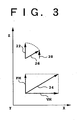
- FIG. 3 is a view for illustrating the principle of changing of the Faraday rotation angle by using the Faraday rotator FR shown in FIG. 2 .
- the vertical axis and the horizontal axis in FIG. 3 correspond to the Z axis and the X axis, respectively.
- the magnetization of the crystal 12 is parallel to the Z axis as shown by reference numeral 22.
- the strength of the fixed magnetic field FM is set so that the magnetization of the crystal 12 is saturated by the fixed magnetic field FM only. In this preferred embodiment, when the fixed magnetic field FM only is applied, the Faraday rotation angle becomes 90°.
- the synthetic magnetic field is given as a synthetic vector of the fixed magnetic field FM and the variable magnetic field VM as shown by reference numeral 24.
- This synthetic magnetic field 24 generates a magnetization as shown by reference numeral 26 in the magneto-optic crystal 12.
- the direction of the magnetization 26 is parallel to the direction of the synthetic magnetic field 24, and the magnetization of the magneto-optic crystal 12 is saturated. Therefore, the strength of the magnetization 26 (the length of the magnetization vector) is equal to the strength of the magnetization 22 (the length of the magnetization vector).
- the strength of the magnetization of the magneto-optic crystal 12 is fixed, a degree of contribution of the magnetization to the Faraday rotation angle in the crystal 12 is not the same, because the Faraday rotation angle depends also on the relation between the direction of the magnetization and the light propagation direction. That is, in comparing the condition of the magnetization 22 and the condition of the magnetization 26, a Z-axis component 28 of the magnetization 26 is smaller than a Z-axis component (the magnetization 22 itself) of the magnetization 22. Accordingly, the Faraday rotation angle corresponding to the magnetization 26 is smaller than that corresponding to the magnetization 22.
- the Faraday rotation angle is decreased from 90° toward 0° by changing the drive current for the electromagnet 16 from 0 to a maximum value.
- FIG. 4 is a graph showing the relation between the attenuation and the drive current for the electromagnet 16 in each of the attenuator units AU1 and AU2 shown in FIG. 1 .
- the axes 4A and 6A are perpendicular to each other, and the variable magnetic field VM by the electromagnet 16 is applied in a direction perpendicular to the Z axis. Therefore, the attenuation continuously increases with an increase in the drive current for the electromagnet 16.
- the axes 8A and 10A are parallel to each other, and the variable magnetic field VM by the electromagnet 16 is applied in a direction perpendicular to the Z axis. Therefore, the attenuation continuously decreases with an increase in the drive current for the electromagnet 16.
- FIG. 5 is a graph showing an example of a wavelength characteristic of Faraday rotation angle when the magnetization of a certain magneto-optic crystal is saturated.
- the vertical axis represents Faraday rotation angle (deg/cm) and the horizontal axis represents wavelength ( ⁇ m) of light to which a Faraday rotation angle is given.
- the Faraday rotation angle per unit length decreases with an increase in wavelength.
- the attenuation increases with a decrease in the Faraday rotation angle from 90° toward 0°. Accordingly, letting a 1 (dB), a 2 (dB), and a 3 (dB) denote the attenuations of the lights having the wavelengths ⁇ 1 , ⁇ 2 , and ⁇ 3 , respectively, in the attenuator unit AU1, a 3 ⁇ a 2 ⁇ a 1 holds.
- the attenuation decreases with a decrease in the Faraday rotation angle from 90° toward 0°. Accordingly, the attenuations of the lights having the wavelengths ⁇ 1 , ⁇ 2 , and ⁇ 3 become a 3 (dB), a 2 (dB), and a 1 (dB), respectively, in a substantially linear range of the wavelength characteristic of Faraday rotation angle.
- the attenuation increases with an increase in wavelength in the attenuator unit AU1 whose attenuation increases with an increase in the drive current for the electromagnet 16, whereas the attenuation decreases with an increase in wavelength in the attenuator unit AU2 whose attenuation decreases with an increase in the drive current for the electromagnet 16.
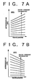
- FIGS. 7A and 7B are graphs showing changes in wavelength characteristics of attenuation in the attenuator units AU1 and AU2, respectively.
- the tendency of the wavelength characteristic of attenuation to tilt positively becomes stronger with an increase in the drive current for the electromagnet 16 as shown in FIG. 7A .
- the tendency of the wavelength characteristic of attenuation to tilt negatively becomes stronger with an increase in the drive current as shown in FIG. 7B .
- ⁇ F1 denote the Faraday rotation angle in the attenuator unit AU1
- the attenuation (dB) by the attenuator unit AU1 is given by the following expression. 10 ⁇ log sin 2 ⁇ ⁇ F ⁇ 1
- a change in transmitted light power with an increase in wavelength by ⁇ is expressed as follows: - sin 2 ⁇ ⁇ F ⁇ 1 ⁇ sin K ⁇ ⁇ F ⁇ 1 ⁇ ⁇ ⁇ ⁇
- K is a coefficient in the case where primary approximation of the wavelength characteristic of Faraday rotation angle is made.
- ⁇ F2 denote the Faraday rotation angle in the attenuator unit AU2
- the attenuation (dB) by the attenuator unit AU2 is given by the following expression. 10 ⁇ log ⁇ 90 ⁇ ° - ⁇ F ⁇ 2
- a change in transmitted light power with an increase in wavelength by ⁇ is expressed as follows: - sin 2 ⁇ ⁇ F ⁇ 2 ⁇ sin K ⁇ ⁇ F ⁇ 2 ⁇ ⁇ ⁇ ⁇ ⁇
- the wavelength characteristic of total attenuation in the optical attenuator shown in FIG. 1 can be flattened.
- each Faraday rotation angle may be controlled under the condition where the Faraday rotation angle in the attenuator unit AU1 and the Faraday rotation angle in the attenuator unit AU2 are equal to each other, whereas in the case where the total attenuation is relatively small, e.g., in the case where the sum of attenuations below the intersection is the total attenuation, each Faraday rotation angle may be controlled under the.condition where the Faraday rotation angle in the attenuator unit AU1 and the Faraday rotation angle in the attenuator unit AU2 are different from each other.
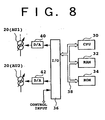
- control circuit 2 suitable for such flexible control will now be described with reference to FIG. 8 .
- FIG. 8 is a block diagram showing a preferred embodiment of the control circuit 2.
- the control circuit 2 includes a CPU (Central Processing Unit) 30 for performing computation and the like for decision of a drive current for each electromagnet 16 according to a control input for providing a desired attenuation, a RAM (Random Access Memory) 32 for temporarily storing data on the results of computation and the like, a ROM (Read Only Memory) 34 preliminarily storing a program, data, etc. required for the computation, and an I/O port 36 for inputting and outputting data.
- the CPU 30, the RAM 32, the ROM 34, and the I/O port 36 are interconnected by a data bus 38.
- Stored in the ROM 34 is a data table representing the relation between a group of solutions of the afore-mentioned equation previously obtained and attenuations obtained by the solutions.
- the solution for obtaining the attenuation is selected by the CPU 30, and the Faraday rotation angles in the attenuator units AU1 and AU2 are set so as to satisfy the solution.
- digital data output from the I/O port 36 are converted into analog control signals by D/A converters 40 and 42, which are next supplied to the variable current sources 20 of the attenuator units AU1 and AU2, respectively. Accordingly, the drive current for each electromagnet 16 is set to carry out combination of the Faraday rotation angles for obtaining the desired attenuation.
- the electromagnet 16 in the attenuator unit AU1 is driven in a region where the Faraday rotation angle in the attenuator unit AU1 is close to 90°
- the electromagnet 16 in the attenuator unit AU2 is driven in a region where the Faraday rotation angle in the attenuator unit AU2 is close to 0°.
- control circuit 2 controls each Faraday rotation angle so that the wavelength characteristic of attenuation in the attenuator unit AU1 is substantially canceled by the wavelength characteristic of attenuation in the attenuator unit AU2. Accordingly, the wavelength characteristic of total attenuation can be flattened.
- FIG. 9 is a view showing a second preferred embodiment of the optical attenuator according to the present invention.
- This preferred embodiment is characterized in that a modified Faraday rotator FR' and polarizer 10' are used in place of the Faraday rotator FR and the polarizer 10 of the attenuator unit AU2 in the first preferred embodiment shown in FIG. 1 .
- an internal configuration of the Faraday rotator FR' is not shown, it is modified in such a manner that a variable magnetic field VM is set parallel to the optical path OP and a fixed magnetic field FM is set perpendicular to the optical path OP.
- the polarizer 10' has an axis 10A' parallel to the Y axis.
- the attenuation by the attenuator unit AU2 decreases with an increase in drive current for an electromagnet in the attenuator unit AU2. Accordingly, in accordance with the principle similar to that in the first preferred embodiment shown in FIG. 1 , the wavelength characteristic of attenuation in the attenuator unit AU1 is substantially canceled by the wavelength characteristic of attenuation in the attenuator unit AU2, thereby flattening the wavelength characteristic of total attenuation.
- FIG. 10 is a view showing a third preferred embodiment of the optical attenuator according to the present invention.
- This preferred embodiment is characterized in that a modified polarizer 10' is used in place of the polarizer 10 of the attenuator unit AU2 in the first preferred embodiment shown in FIG. 1 .
- the polarizer 10' has an axis 10A' parallel to the Y axis.
- the axes 8A and 10A' are orthogonal to each other, and the axes 4A and 6A are also orthogonal to each other.
- the Faraday rotators FR in the attenuator units AU1 and AU2 are the same, so that the attenuator units AU1 and AU2 operate similarly.
- the attenuation increases with an increase in drive current for the electromagnet 16. Further, in each of the attenuator units AU1 and AU2, the tendency of the wavelength characteristic of attenuation to tilt positively is stronger with an increase in the drive current as shown in FIG. 7A .
- the wavelength characteristic given as the sum of the wavelength characteristic of attenuation in the attenuator unit AU1 and the wavelength characteristic of attenuation in the attenuator unit AU2 can be set so as to have a desired tilt. That is, according to this preferred embodiment, the wavelength characteristic of total attenuation can be easily adjusted. Further, because the two attenuator units AU1 and AU2 operating similarly are cascaded, a dynamic range of adjustment of the wavelength characteristic of total attenuation is widened.
- any one of the polarizers 6 and 8 may be omitted because the axes 6A and 8A are parallel to each other.
- the optical attenuator is used in such a manner that light passes through the attenuator units AU1 and AU2 in this order along the optical path OP and that the light input to the attenuator unit AU1 is linearly polarized light having a polarization plane parallel to the YZ plane, the polarizer 4 may also be omitted.
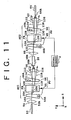
- FIG. 11 is a view showing a fourth preferred embodiment of the optical attenuator according to the present invention.
- This preferred embodiment is characterized in that wedge plates 44, 46, 48, and 50 of birefringent crystals are provided in place of the polarizers 4, 6, 8, and 10 shown in FIG. 1 .
- an optical fiber 52 and a lens 54 each for an input light beam; a lens 56, an optical fiber 58, and a lens 60 each for optically coupling attenuator units AU1 and AU2; and a lens 62 and an optical fiber 64 each for an output light beam.
- An optical path connecting the optical fibers 52 and 58 is provided by an ordinary ray and an extraordinary ray defined in each of the wedge plates 44 and 46, and an optical path connecting the optical fibers 58 and 64 is provided by an ordinary ray and an extraordinary ray defined in each of the wedge plates 48 and 50.
- Attenuation in the optical path connecting the optical fibers 52 and 58 is determined by the Faraday rotation angle in the Faraday rotator FR of the attenuator unit AU1
- attenuation in the optical path connecting the optical fibers 58 and 64 is determined by the Faraday rotation angle in the Faraday rotator FR of the attenuator unit AU2.
- the output optical fiber 64 is optically coupled to the input optical fiber 52 with a coupling efficiency according to each Faraday rotation angle, thereby obtaining a desired total attenuation.
- Each of the wedge plates 44 and 46 has a wedge angle defined on a first plane
- each of the wedge plates 48 and 50 has a wedge angle defined on a second plane.
- the first and second planes are parallel to the YZ plane.
- the wedge plates 44 and 46 have principal axes 44A and 46A, respectively, each for determining an ordinary ray and an extraordinary ray.
- the wedge plates 48 and 50 have principal axes 48A and 50A, respectively, each for determining an ordinary ray and an extraordinary ray.
- the principal axis 44A is parallel to the X axis
- the principal axes 46A, 48A, and 50A are parallel to the Y axis.
- the wedge plates 44 and 46 have the same shape and they are arranged in such a manner that a top portion and a bottom portion of the wedge plate 44 are opposed to a bottom portion and a top portion of the wedge plate 46, respectively, and that corresponding surfaces of the wedge plates 44 and 46 are parallel to each other.
- the wedge plates 48 and 50 have the same shape and they are arranged in such a manner that a top portion and a bottom portion of the wedge plate 48 are opposed to a bottom portion and a top portion of the wedge plate 50, respectively, and that corresponding surfaces of the wedge plates 48 and 50 are parallel to each other.
- the beam 102 is separated into a beam 104 corresponding to the ordinary ray and a beam 106 corresponding to the extraordinary ray in the wedge plate 44.
- the beams 104 and 106 undergo Faraday rotation by the same Faraday rotation angle in the same direction in the Faraday rotator FR to become beams 108 and 110, respectively.
- the beam 108 is separated into a beam 112 corresponding to the ordinary ray and a beam 114 corresponding to the extraordinary ray in the wedge plate 46.
- the beam 110 is separated into a beam 116 corresponding to the extraordinary ray and a beam 118 corresponding to the ordinary ray in the wedge plate 46.
- the beams 112 and 116 are parallel to each other and the beams 114 and 118 are not parallel to each other. Accordingly, the beams 112 and 116 parallel to each other can be focused by the lens 56 to enter a fiber end 58A of the optical fiber 58. On the other hand, the beams 114 and 118 not parallel to each other are deviated from the optical path and do not enter the fiber end 58A.
- the attenuation in the attenuator unit AU1 corresponds to the ratio of the total power of the beams 112 and 116 to the power of the beam 102.
- the Faraday rotation angle of the Faraday rotator FR in the attenuator unit AU1 is 90°
- the power of the beam 104 is entirely shifted to the power of the beam 112 in principle
- the power of the beam 106 is entirely shifted to the power of the beam 116 in principle. Accordingly, the attenuation in the attenuator unit AU1 is minimized.
- the Faraday rotation angle of the Faraday rotator FR is 0°
- the power of the beam 104 is entirely shifted to the power of the beam 114 in principle
- the power of the beam 106 is entirely shifted to the power of the beam 118 in principle. Accordingly, the attenuation in the attenuator unit AU1 is maximized.
- the attenuation according to the Faraday rotation angle of the Faraday rotator FR is obtained in the attenuator unit AU1.
- the attenuation in the attenuator unit AU1 is not dependent on the polarization state of the beam 102 (i.e., input beam).
- the light entered the fiber end 58A of the optical fiber 58 emerges from another fiber end 58B of the optical fiber 58 and is next collimated by the lens 60 to become a parallel light beam.
- This beam is denoted by reference numeral 122 with the beam thickness neglected.
- the beam 122 is separated into a beam 124 corresponding to the ordinary ray and a beam 126 corresponding to the extraordinary ray in the wedge plate 48.
- the beams 124 and 126 undergo Faraday rotation by the same Faraday rotation angle in the same direction in the Faraday rotator FR of the attenuator unit AU2 to become beams 128 and 130, respectively.
- the beam 128 is separated into a beam 132 corresponding to the ordinary ray and a beam 134 corresponding to the extraordinary ray in the wedge plate 50.
- the beam 130 is separated into a beam 136 corresponding to the extraordinary ray and a beam 138 corresponding to the ordinary ray in the wedge plate 50.
- the beams 132 and 136 enter a fiber end 64A of the optical fiber 64, and the beams 134 and 138 are deviated from the optical path and do not enter the fiber end 64A.
- the attenuation in the attenuator unit AU2 is not dependent on the polarization state of the input beam (beam 122).
- the principal axes 48A and 50A are parallel to each other in contrast with the fact that the principal axes 44A and 46A are perpendicular to each other, the tendency of the attenuation to change with a change in the Faraday rotation angle in the attenuator unit AU2 is reverse to that in the attenuator unit AU1.
- the Faraday rotation angle in the attenuator unit AU2 is 90°
- the power of the beam 124 is entirely shifted to the power of the beam 134 in principle
- the power of the beam 126 is entirely shifted to the power of the beam 138 in principle. Accordingly, the attenuation in the attenuator unit AU2 is maximized.
- the Faraday rotation angle in the attenuator unit AU2 is 0°
- the power of the beam 124 is entirely shifted to the power of the beam 132 in principle
- the power of the beam 126 is entirely shifted to the power of the beam 136 in principle. Accordingly, the attenuation in the attenuator unit AU2 is minimized.
- the wavelength characteristic of attenuation in the attenuator unit AU1 is substantially canceled by the wavelength characteristic of attenuation in the attenuator unit AU2, thereby flattening the wavelength characteristic of total attenuation in the optical attenuator.
- the use of the optical fiber 58 and the lenses 56 and 60 to optically connect the attenuator units AU1 and AU2 in the fourth preferred embodiment shown in FIG. 11 is due to the following reason. That is, in the case that the attenuator units AU1 and AU2 are optically connected by a spatial beam without using the optical fiber 58 and the lenses 56 and 60, a part or the whole of the powers of the beams 112 and 116 are expected to be shifted to the powers of the beams 132 and 136, whereas the power of the beam 114 or 118 deviated from the optical path may be shifted to the powers of the beams 132 and 136, so that a required attenuation cannot possibly be obtained.
- Such undesired recombination is caused primarily by the fact that the first plane defining the wedge angles of the wedge plates 44 and 46 is parallel to the second plane defining the wedge angles of the wedge plates 48 and 50. Accordingly, by rotating one of the first and second planes relative to the other about the Z axis to thereby make the first and second planes nonparallel to each other; the optical fiber 58 and the lenses 56 and 60 may be omitted to suppress an insertion loss in the optical attenuator. For example, the first and second planes may be made perpendicular to each other. A specific embodiment of this configuration will be described below.
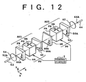
- FIG. 12 is a view showing a fifth preferred embodiment of the optical attenuator according to the present invention.
- the fifth preferred embodiment is characterized in that the wedge plates 44 and 46 are rotated 90° about the Z axis to thereby allow omission of the optical fiber 58 and the lenses 56 and 60 shown in FIG. 11 .
- the plane defining the wedge angles of the wedge plates 48 and 50 is parallel to the YZ plane, whereas the plane defining the wedge angles of the wedge plates 44 and 46 is parallel to the XZ plane.
- the principal axis 44A is parallel to the Y axis, and the principal axis 46A is parallel to the X axis.
- an optical attenuator having a flat wavelength characteristic of attenuation and a polarization independence such that the attenuation is not dependent on the polarization state of an input beam.
- an insertion loss in the optical attenuator can be reduced by the omission of the optical fiber 58 and the lenses 56 and 60 used in the fourth preferred embodiment shown in FIG. 11 .
- FIG. 13 is a graph showing measurement results on the wavelength characteristic of attenuation in the attenuator unit AU1 shown in FIG. 12 .
- the vertical axis represents deviation (dB) of attenuation
- the horizontal axis represents wavelength (nm).
- the principal axes 44A and 46A are perpendicular to each other. Accordingly, as the drive current for the electromagnet 16 of the Faraday rotator FR (see FIG. 2 ) is increased from 0, the Faraday rotation angle obtained is decreased from 90° toward 0° Therefore, the attenuation is expected to increase with an increase in the drive current.
- the attenuations to a wavelength of 1545 nm at these set values were measured to obtain 1.3 dB, 2.0 dB, 7.1 dB, 13.4 dB, 17.3 dB, 21.8 dB, and 27.1 dB, respectively. Further, it was found that the positive tilt of the wavelength characteristic of attenuation is gradually increased with an increase in the drive current. This measurement result coincides with the wavelength characteristic of attenuation previously described with reference to FIG. 7A .
- FIGS. 14A to 14D are graphs showing measurement results on the wavelength characteristic of total attenuation in the optical attenuator in the preferred embodiment shown in FIG. 12 .
- the wavelength characteristic of total attenuation was measured by inputting light from an LED as a substantially white light source in a given wavelength band (1530 nm to 1560 nm) to the optical attenuator and inputting output light from the optical attenuator to an optical spectrum analyzer.
- FIG. 14A shows a measurement result in the case that the drive current I 1 in the attenuator unit AU1 was set to 10.5 mA and the drive current I 2 in the attenuator unit AU2 was set to 7.9 mA.
- the attenuation obtained is 10 dB over the given wavelength band, and the wavelength characteristic of attenuation is sufficiently flat.
- FIG. 15 is a view showing a sixth preferred embodiment of the optical attenuator according to the present invention.
- the variable magnetic field VM increases with an increase in the drive current, and accordingly the Faraday rotation angle decreases from 90° toward 0°.
- the sixth preferred embodiment shown in FIG. 15 employs a Faraday rotator FR' in which the directions of application of the variable magnetic field VM and the fixed magnetic field FM are reverse to those in the Faraday rotator FR in the fifth preferred embodiment. Accordingly, as the drive current in the Faraday rotator FR' is increased from 0, the Faraday rotation angle increases from 0° toward 90°.
- the sixth preferred embodiment shown in FIG. 15 employs a wedge plate 50' having a principal axis 50A' orthogonal to the principal axis 48A of the wedge plate 48.
- the principal axis 50A' is parallel to the X axis.
- an optical attenuator having a flat wavelength characteristic of attenuation and a polarization independence such that the attenuation is not dependent on the polarization state of an input beam as understood in accordance with the principles of the second preferred embodiment shown in FIG. 9 and the fifth preferred embodiment shown in FIG. 12 .
- FIG. 16 is a view showing a seventh preferred embodiment of the optical attenuator according to the present invention.
- the seventh preferred embodiment shown in FIG. 16 uses a wedge plate 50' having a principal axis 50A' parallel to the X axis.
- the wavelength characteristic of attenuation in the attenuator unit AU1 and the wavelength characteristic of attenuation in the attenuator unit AU2 have the same tendency. Accordingly, as understood in accordance with the operating principles of the third preferred embodiment shown in FIG. 10 and the fifth preferred embodiment shown in FIG. 12 , it is possible to provide an optical attenuator having a freely adjustable wavelength characteristic of attenuation and a polarization independence such that the attenuation is not dependent on the polarization state of an input beam.
- a plurality of wedge plates of birefringent crystals are combined in each of the fourth to seventh preferred embodiments mentioned above to allow the provision of a polarization-independent optical attenuator
- a plurality of parallel-plane plates of birefringent crystals may be combined to provide a polarization-independent optical attenuator.
- a converging beam system is preferably adopted in place of the parallel beam system adopted in the case of the combination of the wedge plates.
- An optical amplifier known in the art includes an optical amplifying medium to which signal light to be amplified is supplied and means for pumping (exciting) the optical amplifying medium so that the optical amplifying medium provides a gain band including the wavelength of the signal light.
- an erbium doped fiber amplifier includes an erbium doped fiber (EDF) as the optical amplifying medium and a pumping source for supplying pump light having a predetermined wavelength to the EDF.
- a gain band including a wavelength band of 1.55 ⁇ m can be obtained.
- another type optical amplifier having a semiconductor chip as the optical amplifying medium is also known. In this case, the pumping is performed by injecting an electric current into the semiconductor chip.
- wavelength division multiplexing As a technique for increasing a transmission capacity by a single optical fiber, wavelength division multiplexing (WDM) is known.
- WDM wavelength division multiplexing
- a plurality of optical carriers having different wavelengths are used.
- the plural optical carriers are individually modulated to thereby obtain a plurality of optical signals, which are wavelength division multiplexed by an optical multiplexer to obtain WDM signal light, which is output to an optical fiber transmission line.
- the WDM signal light received is separated into individual optical signals by an optical demultiplexer, and transmitted data is reproduced according to each optical signal. Accordingly, by applying WDM, the transmission capacity in a single optical fiber can be increased according to the number of WDM channels.
- a transmission distance is limited by a wavelength characteristic of gain represented by a gain tilt or gain deviation.
- a gain tilt is produced at wavelengths in the vicinity of 1.55 ⁇ m and that this gain tilt changes according to the total input power of signal light into the EDFA and the power of pump light.
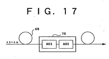
- FIG. 17 is a block diagram showing a preferred embodiment of the system according to the present invention.
- This system includes an optical fiber transmission line 68 for transmitting wavelength division multiplexed light (WDM light) including a plurality of optical signals having different wavelengths, and an optical attenuator 70 provided in (or arranged along) the optical fiber transmission line 68.
- the optical attenuator 70 has attenuator units AU1 and AU2 each for giving a variable attenuation to the WDM light.
- the attenuator units AU1 and AU2 have a first wavelength characteristic of attenuation and a second wavelength characteristic of attenuation, respectively; which are different from each other.
- the wavelengths of the plural optical signals included in the WDM light are represented by ⁇ 1 to ⁇ n .
- the optical fiber transmission line 68 includes a plurality of in-line optical amplifiers and that each optical amplifier has a wavelength characteristic of gain in the band of the WDM light, the wavelength characteristic of gain is accumulated to cause an interchannel deviation in signal power or optical signal-to-noise ratio (optical SNR).
- the wavelength characteristic of attenuation provided by the optical attenuator 70 can be freely adjusted by configuring the optical attenuator 70. Accordingly, the cumulative wavelength characteristic of attenuation can be compensated to thereby reduce the interchannel deviation in signal power or optical SNR.
- the wavelength characteristic of attenuation in the attenuator unit AU1 and the wavelength characteristic of attenuation in the attenuator unit AU2 may be substantially canceled by each other to maintain the flat wavelength characteristic of gain under control by configurating the optical attenuator 70.
- FIGS. 18A, 18B, and 18C are block diagrams showing preferred embodiments of the optical amplifier according to the present invention. The configuration and operation of each optical amplifier will now be described provided that each optical amplifier is applied to the system shown in FIG. 17 .
- an optical amplifier 71 including two optical amplifying units 72 (#1 and #2) and an optical attenuator 70 provided between the two optical amplifying units 72 (#1 and #2).
- the optical attenuator 70 includes two attenuator units AU1 and AU2 each for giving a variable attenuation.
- the attenuator units AU1 and AU2 have first and second wavelength characteristics of attenuation, respectively, which are different from each other.
- WDM light to be amplified is first amplified by the optical amplifying unit 72 (#1), and attenuation is given to the amplified WDM light by the optical attenuator 70. Then, the WDM light attenuated is amplified by the optical amplifying unit 72 (#2) to be finally output from the optical amplifier 71.
- the first and second wavelength characteristics of attenuation are set so as to cancel each other.
- the first and second wavelength characteristics of attenuation may be set so that the wavelength characteristic of light to be output from the optical amplifying unit 72 (#2) (specifically, the wavelength characteristic of power of WDM light) becomes flat.
- an optical amplifier 71 including an optical amplifying unit 72 and an optical attenuator 70 connected to the output of the optical amplifying unit 72.
- the first and second wavelength characteristics of attenuation are set so as to cancel each other so that the wavelength characteristic of gain of the optical amplifying unit 72 is not changed by the operation of the optical attenuator 70.
- an optical amplifier 71 including an optical amplifying unit 72 and an optical attenuator 70 connected to the input of the optical amplifying unit 72.
- the first and second wavelength characteristics of attenuation are set so as to cancel each other so that the wavelength characteristic of WDM light to be supplied to the optical amplifying unit 72 and amplified therein is not changed.
- the first and second wavelength characteristics of attenuation may be set so as to cancel the wavelength characteristic of gain in the optical amplifying unit 72.
- FIG. 19 is a block diagram showing a preferred embodiment of the terminal device according to the present invention.
- a terminal device 74 is connected to an input end of an optical fiber transmission line 68.
- the terminal device 74 includes a plurality of E/O (electro/optic) converters 76 (#1 to #n) for outputting optical signals having different wavelengths ⁇ 1 to ⁇ n , respectively, and a plurality of optical attenuators 70 (#1 to #n) for adjusting the levels of these optical signals output from the E/O converters 76 (#1 to #n), respectively.
- Each of the optical attenuators 70 (#1 to #n) is used as a so-called level adjusting unit.
- the optical signals output from the optical attenuators 70 (#1 to #n) are wavelength division multiplexed by an optical multiplexer 78 to obtain WDM light, which is in turn amplified by an optical amplifier 71 and next supplied to the optical fiber transmission line 68.
- Each of the preferred embodiments shown in FIGS. 18A, 18B, and 18C may be applied to the optical amplifier 71.
- Each of the E/O converters 76 (#1 to #n) includes a laser diode (LD) 80 for outputting CW light (continuous wave light) and an optical modulator 82 for modulating the CW light output from the LD 80 according to a main signal.
- LD laser diode
- each of the optical attenuators 70 (#1 to #n) a substantially flat wavelength characteristic of attenuation or a desired wavelength characteristic of attenuation is obtained. Accordingly, the wavelength characteristic of power of the optical signal output from each of the E/O converters 76 (#1 to #n) can be maintained to thereby maintain constant the wavelength characteristic of power of the WDM light obtained.
- the optical amplifier 71 has the optical attenuator 70 as a component. Accordingly, the wavelength characteristic of power of the WDM light obtained can be made flat or set to a desired characteristic.
- the terminal device 74 may exclude the optical attenuators 70 (#1 to #n) or the optical amplifier 71.
- an optical attenuator having a flat wavelength characteristic of attenuation or an adjustable wavelength characteristic of attenuation.
Landscapes
- Physics & Mathematics (AREA)
- Nonlinear Science (AREA)
- Engineering & Computer Science (AREA)
- Power Engineering (AREA)
- General Physics & Mathematics (AREA)
- Optics & Photonics (AREA)
- Optical Modulation, Optical Deflection, Nonlinear Optics, Optical Demodulation, Optical Logic Elements (AREA)
- Optical Communication System (AREA)
Claims (8)
- Dispositif comprenant :des première et seconde unités d'atténuateur (AU1, AU2) chacune destinées à fournir une atténuation variable ;ladite première et seconde unités d'atténuateur ayant des première et seconde caractéristiques de longueur d'onde d'atténuation, respectivement, qui sont différentes les unes des autres sur chaque atténuation de ladite atténuation variable ;dans lequel chacune desdites première et seconde unités d'atténuateur possède un polarisateur (4, 6, 8, 10) destiné à déterminer un plan de polarisation de la lumière qui passe à travers ceux-ci, et un rotateur de Faraday destiné à générer un angle de rotation de Faraday donné en fonction de la longueur d'onde ;ledit dispositif comprenant en outre une unité de commande reliée à chacun desdits rotateurs de Faraday ;dans lequel ladite unité de commande comprend des moyens destinés à contrôler chaque angle de rotation de Faraday afin que la première caractéristique de longueur d'onde d'atténuation soit sensiblement annulée par la seconde caractéristique de longueur d'onde d'atténuation de façon à aplanir une caractéristique de longueur d'onde d'atténuation totale sur chaque atténuation de ladite atténuation variable.
- Dispositif selon la revendication 1, comprenant en outre :une ligne de transmission de fibre optique (68) destinée à transmettre une lumière multiplexée par répartition de longueur d'onde comprenant une pluralité de signaux optiques ayant différentes longueurs d'onde.
- Dispositif selon la revendication 1, comprenant en outre :une première unité d'amplification optique (72(#1)) ; etune seconde unité d'amplification optique (72(#2)) ;dans lequel lesdites première et seconde unités d'atténuateur (AU1, AU2) sont placées entre lesdites première et seconde unités d'amplification optique.
- Dispositif selon la revendication 3, dans lequel lesdites première et seconde caractéristiques de longueur d'onde d'atténuation annulent sensiblement une caractéristique de longueur d'onde de la lumière fournie par ladite seconde unité d'amplification optique.
- Dispositif selon la revendication 1, comprenant en outre :une unité d'amplification optique (72) ; etun atténuateur optique (70) raccordé à une sortie de ladite unité d'amplification optique ;dans lequel ledit atténuateur optique (70) comprend lesdites première et seconde unités d'atténuateur (AU1, AU2).
- Dispositif selon la revendication 1, comprenant en outre :une unité d'amplification optique (72) ; etun atténuateur optique (70) raccordé à une entrée de ladite unité d'amplification optique ;dans lequel ledit atténuateur optique (70) comprend lesdites première et seconde unités d'atténuateur (AU1, AU2).
- Dispositif selon la revendication 1, comprenant en outre :une pluralité de convertisseurs E/O (76(#1) - 76(#n)) pour fournir respectivement des signaux optiques ayant différentes longueurs d'onde ;une pluralité d'unités d'ajustement de niveaux (70(#1)-70(#n)) pour ajuster respectivement les niveaux desdits signaux optiques fournis par lesdits convertisseurs E/O ; etun multiplexeur optique (78) pour multiplexer par répartition de longueur d'onde lesdits signaux optiques fournis par lesdites unités d'ajustement de niveaux pour obtenir la lumière multiplexée par répartition de longueur d'onde ;chacune desdites unités d'ajustement de niveaux (70(#1)-70(#n)) comprenant lesdites première et seconde unités d'atténuateur (AU1, AU2).
- Dispositif selon la revendication 1, comprenant en outre :une pluralité de convertisseurs E/O (76(#1)-76(#n)) pour fournir respectivement des signaux optiques ayant différentes longueurs d'onde ;une pluralité d'unités d'ajustement de niveaux (70(#1)-70(#n)) pour ajuster respectivement les niveaux desdits signaux optiques fournis par lesdits convertisseurs E/O ;un multiplexeur optique (78) pour multiplexer par répartition de longueur d'onde lesdits signaux optiques fournis par lesdites unités d'ajustement de niveaux pour obtenir la lumière multiplexée par répartition de longueur d'onde ; etun amplificateur optique (71) pour amplifier ladite lumière multiplexée par répartition de longueur d'onde fournie par ledit multiplexeur optique ;ledit amplificateur optique (71) comprenant une unité d'amplification optique (72) et un atténuateur optique (70) raccordé à ladite unité d'amplification optique, et ledit atténuateur optique (70) comprenant lesdites première et seconde unités d'atténuateur (AU1, AU2).
Applications Claiming Priority (3)
| Application Number | Priority Date | Filing Date | Title |
|---|---|---|---|
| JP01014498A JP3829962B2 (ja) | 1998-01-22 | 1998-01-22 | 光アッテネータ並びに該光アッテネータを備えたシステム、光増幅器及び端局装置 |
| JP1014498 | 1998-01-22 | ||
| EP98112558A EP0932067B1 (fr) | 1998-01-22 | 1998-07-07 | Atténuateur optique |
Related Parent Applications (2)
| Application Number | Title | Priority Date | Filing Date |
|---|---|---|---|
| EP98112558.6 Division | 1998-07-07 | ||
| EP98112558A Division EP0932067B1 (fr) | 1998-01-22 | 1998-07-07 | Atténuateur optique |
Publications (3)
| Publication Number | Publication Date |
|---|---|
| EP1174754A2 EP1174754A2 (fr) | 2002-01-23 |
| EP1174754A3 EP1174754A3 (fr) | 2004-03-24 |
| EP1174754B1 true EP1174754B1 (fr) | 2013-05-15 |
Family
ID=11742100
Family Applications (2)
| Application Number | Title | Priority Date | Filing Date |
|---|---|---|---|
| EP98112558A Expired - Lifetime EP0932067B1 (fr) | 1998-01-22 | 1998-07-07 | Atténuateur optique |
| EP01120688.5A Expired - Lifetime EP1174754B1 (fr) | 1998-01-22 | 1998-07-07 | Atténuateur optique |
Family Applications Before (1)
| Application Number | Title | Priority Date | Filing Date |
|---|---|---|---|
| EP98112558A Expired - Lifetime EP0932067B1 (fr) | 1998-01-22 | 1998-07-07 | Atténuateur optique |
Country Status (5)
| Country | Link |
|---|---|
| US (2) | US6407836B1 (fr) |
| EP (2) | EP0932067B1 (fr) |
| JP (1) | JP3829962B2 (fr) |
| CN (1) | CN1170186C (fr) |
| DE (1) | DE69808421T2 (fr) |
Families Citing this family (32)
| Publication number | Priority date | Publication date | Assignee | Title |
|---|---|---|---|---|
| JP3737628B2 (ja) | 1998-03-20 | 2006-01-18 | 富士通株式会社 | 利得等価器及び光増幅器 |
| US7170673B2 (en) * | 1999-07-30 | 2007-01-30 | Mitsubishi Denki Kabushiki Kaisha | Optical amplifying repeater apparatus and optical amplifying/repeating transmission system |
| US6657778B1 (en) * | 1999-07-30 | 2003-12-02 | Mitsubishi Denkikabushiki Kaisha | Optical amplification repeater and optical amplification repeating and transmitting system |
| US6442310B1 (en) * | 2000-07-14 | 2002-08-27 | Jds Uniphase Inc. | Optical coupling device and method |
| US20020009254A1 (en) * | 2000-07-24 | 2002-01-24 | Zhifeng Sui | High switching speed digital faraday rotator device and optical switches reduced cross talk and state sensing capability |
| US6876480B2 (en) | 2000-08-11 | 2005-04-05 | Fdk Corporation | Farady rotation device and optical device comprising it |
| AU2000275563A1 (en) * | 2000-10-04 | 2002-04-15 | Mitsubishi Denki Kabushiki Kaisha | Optical variable attenuator |
| JP2002268028A (ja) * | 2001-03-09 | 2002-09-18 | Furukawa Electric Co Ltd:The | 可変光学フィルタユニットおよび可変利得等化システム |
| US6608723B2 (en) * | 2001-03-16 | 2003-08-19 | Finisar Corporation | Integrated pump combining module |
| US7230964B2 (en) * | 2001-04-09 | 2007-06-12 | Cymer, Inc. | Lithography laser with beam delivery and beam pointing control |
| CA2444965A1 (fr) * | 2001-04-30 | 2002-11-07 | Pirelli Submarine Telecom Systems Italia S.P.A. | Systeme de transmission optique comportant un systeme de supervision |
| US20050259709A1 (en) | 2002-05-07 | 2005-11-24 | Cymer, Inc. | Systems and methods for implementing an interaction between a laser shaped as a line beam and a film deposited on a substrate |
| US6798566B2 (en) * | 2001-06-15 | 2004-09-28 | Fdk Corporation | Variable optical gain equalizer and variable branching ratio beam splitter |
| US6597494B2 (en) * | 2001-07-13 | 2003-07-22 | Fujikura Ltd. | Polarization maintaining optical fiber amplifier and optical amplifier |
| GB2378525A (en) * | 2001-08-08 | 2003-02-12 | Bookham Technology Plc | Optic system |
| GB2378524A (en) * | 2001-08-08 | 2003-02-12 | Bookham Technology Plc | Intergrated optic device |
| JP3718152B2 (ja) * | 2001-09-27 | 2005-11-16 | Fdk株式会社 | 可変光アッテネータ |
| US20050100072A1 (en) * | 2001-11-14 | 2005-05-12 | Rao Rajasekhar M. | High power laser output beam energy density reduction |
| US6873462B2 (en) * | 2002-04-09 | 2005-03-29 | Oplink Communications, Inc. | Three-port circulator |
| US6987896B1 (en) | 2002-04-09 | 2006-01-17 | Oplink Communications, Inc. | Optical isolator |
| US6900933B1 (en) | 2002-04-23 | 2005-05-31 | Oplink Communications, Inc. | Integrated two-pump combiner for optical fiber amplifiers |
| JP3771228B2 (ja) | 2002-08-12 | 2006-04-26 | Tdk株式会社 | 磁気光学光部品 |
| US6839170B2 (en) * | 2002-10-15 | 2005-01-04 | Oplink Communications, Inc. | Optical isolator |
| US7277188B2 (en) * | 2003-04-29 | 2007-10-02 | Cymer, Inc. | Systems and methods for implementing an interaction between a laser shaped as a line beam and a film deposited on a substrate |
| US7317179B2 (en) | 2005-10-28 | 2008-01-08 | Cymer, Inc. | Systems and methods to shape laser light as a homogeneous line beam for interaction with a film deposited on a substrate |
| US7679029B2 (en) | 2005-10-28 | 2010-03-16 | Cymer, Inc. | Systems and methods to shape laser light as a line beam for interaction with a substrate having surface variations |
| JP4983312B2 (ja) * | 2007-02-28 | 2012-07-25 | 住友電気工業株式会社 | 光送信モジュール及びその出射光の波長変化又は劣化を検知する方法 |
| CN101788719B (zh) * | 2009-12-31 | 2011-05-18 | 华中科技大学 | 一种获取衰光率连续且小于偏振片消光比的方法及衰减器 |
| DE102011052217B4 (de) * | 2011-07-27 | 2019-08-08 | Helmholtz-Zentrum Dresden - Rossendorf E.V. | Verfahren zum Bestimmen der wellenlängenabhängigen magnetooptischen Kopplungskonstante einer zu charakterisierenden Schicht in einem Schichtsystem mit einer oder mehreren magnetisierbaren Schichten |
| CN103748450A (zh) * | 2011-08-19 | 2014-04-23 | 马尔文仪器有限公司 | 双模式微粒表征 |
| CN104518827A (zh) * | 2013-09-27 | 2015-04-15 | 华为技术有限公司 | 一种光功率的调节方法及网络设备 |
| CN114441032B (zh) * | 2022-01-19 | 2024-06-21 | 西北核技术研究所 | 基于楔镜组级联衰减的高能激光功率溯源传递系统及方法 |
Family Cites Families (31)
| Publication number | Priority date | Publication date | Assignee | Title |
|---|---|---|---|---|
| JPS56161520A (en) | 1980-05-19 | 1981-12-11 | Fujitsu Ltd | Optical variable attenuator |
| JPH0812281B2 (ja) | 1985-11-13 | 1996-02-07 | 富士通株式会社 | 光減衰板 |
| JPS6377015A (ja) | 1986-09-20 | 1988-04-07 | Fujitsu Ltd | 光アイソレ−タ |
| JPH01243599A (ja) | 1988-03-25 | 1989-09-28 | Nec Corp | 半導体レーザモジュール |
| JP2567697B2 (ja) | 1989-03-29 | 1996-12-25 | 株式会社トーキン | ファラデー回転装置 |
| US4988170A (en) | 1989-03-31 | 1991-01-29 | Gte Laboratories Incorporated | Quasi-achromatic optical isolators and circulators |
| US5015057A (en) * | 1989-09-21 | 1991-05-14 | Tektronix, Inc. | Liquid crystal fiber optic attenuator and process for making same |
| JP2724505B2 (ja) * | 1989-10-31 | 1998-03-09 | アンリツ株式会社 | 光減衰量校正方法及び光校正装置 |
| US5225922A (en) * | 1991-11-21 | 1993-07-06 | At&T Bell Laboratories | Optical transmission system equalizer |
| US5329350A (en) * | 1992-05-21 | 1994-07-12 | Photon, Inc. | Measuring laser beam parameters using non-distorting attenuation and multiple simultaneous samples |
| US5889609A (en) * | 1992-07-31 | 1999-03-30 | Fujitsu Limited | Optical attenuator |
| US5406404A (en) * | 1993-11-02 | 1995-04-11 | At&T Corp. | Method of mitigating gain peaking using a chain of fiber amplifiers |
| IT1270032B (it) * | 1994-04-14 | 1997-04-28 | Pirelli Cavi Spa | Sistema di telecomunicazione amplificata a multiplazione a divisione di lunghezza d'onda |
| US5539563A (en) * | 1994-05-31 | 1996-07-23 | At&T Corp. | System and method for simultaneously compensating for chromatic dispersion and self phase modulation in optical fibers |
| US5918166A (en) * | 1994-11-30 | 1999-06-29 | Nec Corportion | Level control circuit for portable radio communication apparatus |
| JPH08172233A (ja) | 1994-12-15 | 1996-07-02 | Anritsu Corp | 可変波長光源装置 |
| JP3352570B2 (ja) * | 1995-06-26 | 2002-12-03 | ケイディーディーアイ株式会社 | 波長多重伝送方式の雑音抑圧方法 |
| US5825521A (en) * | 1995-07-24 | 1998-10-20 | Lucent Technologies Inc. | Method of determining inter-symbol interference in transmission systems |
| FR2738698B1 (fr) * | 1995-09-08 | 1997-10-17 | Alcatel Nv | Procede et systeme d'egalisation des niveaux respectifs de puissance des canaux d'un signal optique spectralement multiplexe |
| JPH0993200A (ja) * | 1995-09-27 | 1997-04-04 | Nec Corp | 光増幅中継伝送装置 |
| KR970064034A (ko) * | 1996-02-10 | 1997-09-12 | 김광호 | 다중파장 자동 파워 및 이득 조절용 광전송 시스템 및 레이저 |
| US5900968A (en) * | 1996-02-23 | 1999-05-04 | Lucent Technologies Inc. | Method of fast gain control in WDM optical networks |
| JP3739471B2 (ja) * | 1996-03-01 | 2006-01-25 | 富士通株式会社 | 光可変減衰器 |
| JP3720112B2 (ja) * | 1996-03-18 | 2005-11-24 | 富士通株式会社 | 波長分割多重が適用されるシステム及び光パワー制御装置 |
| US6025947A (en) * | 1996-05-02 | 2000-02-15 | Fujitsu Limited | Controller which controls a variable optical attenuator to control the power level of a wavelength-multiplexed optical signal when the number of channels are varied |
| US5699468A (en) * | 1996-06-28 | 1997-12-16 | Jds Fitel Inc. | Bragg grating variable optical attenuator |
| US6031647A (en) * | 1996-10-23 | 2000-02-29 | Nortel Networks Corporation | Stable power control for optical transmission systems |
| JP3919905B2 (ja) * | 1997-10-20 | 2007-05-30 | 富士通株式会社 | 磁気光学効果を利用した光デバイス |
| US6115157A (en) * | 1997-12-24 | 2000-09-05 | Nortel Networks Corporation | Methods for equalizing WDM systems |
| US5956437A (en) | 1997-12-24 | 1999-09-21 | Northern Telecom Limited | Electrically controllable optical attenuator |
| US6038357A (en) * | 1998-02-03 | 2000-03-14 | E-Tek Dynamics, Inc | PDM-WDM for fiberoptic communication networks |
-
1998
- 1998-01-22 JP JP01014498A patent/JP3829962B2/ja not_active Expired - Fee Related
- 1998-06-30 US US09/106,897 patent/US6407836B1/en not_active Expired - Lifetime
- 1998-07-07 DE DE69808421T patent/DE69808421T2/de not_active Expired - Lifetime
- 1998-07-07 EP EP98112558A patent/EP0932067B1/fr not_active Expired - Lifetime
- 1998-07-07 EP EP01120688.5A patent/EP1174754B1/fr not_active Expired - Lifetime
- 1998-08-27 CN CNB981184987A patent/CN1170186C/zh not_active Expired - Fee Related
-
2000
- 2000-11-27 US US09/722,103 patent/US6507422B1/en not_active Expired - Lifetime
Also Published As
| Publication number | Publication date |
|---|---|
| CN1170186C (zh) | 2004-10-06 |
| EP1174754A2 (fr) | 2002-01-23 |
| CN1224174A (zh) | 1999-07-28 |
| JPH11212043A (ja) | 1999-08-06 |
| US6507422B1 (en) | 2003-01-14 |
| DE69808421D1 (de) | 2002-11-07 |
| US6407836B1 (en) | 2002-06-18 |
| EP0932067A2 (fr) | 1999-07-28 |
| DE69808421T2 (de) | 2003-06-26 |
| EP0932067A3 (fr) | 2000-06-14 |
| EP0932067B1 (fr) | 2002-10-02 |
| EP1174754A3 (fr) | 2004-03-24 |
| JP3829962B2 (ja) | 2006-10-04 |
Similar Documents
| Publication | Publication Date | Title |
|---|---|---|
| EP1174754B1 (fr) | Atténuateur optique | |
| EP0932068B1 (fr) | Filtre optique accordable | |
| US6717713B2 (en) | Variable optical attenuator which applies a magnetic field to a faraday element to rotate the polarization of a light signal | |
| EP1562315B1 (fr) | Amplificateur optique Raman avec source de pompage appropriée | |
| US5524118A (en) | Wavelength-varying multi-wavelength optical filter laser using a single pump light source | |
| EP0665452B1 (fr) | Isolateur optique indépendant de la polarisation | |
| US20040150876A1 (en) | Methods and devices for amplifying optical signals using a depolarizer | |
| US20040008916A1 (en) | Scheme for controlling polarization in waveguides | |
| US6141140A (en) | Optical modulator using isolator and optical transmitter including the same | |
| CA2403180A1 (fr) | Liaison de transmission optique utilisant un amplificateur raman | |
| US6980707B2 (en) | Waveguide type variable optical attenuator | |
| US6882764B1 (en) | Polarization independent packaging for polarization sensitive optical waveguide amplifier | |
| US5636053A (en) | Fiberoptic amplifier system with noise figure reduction | |
| US6958845B2 (en) | Optical control element | |
| US5999305A (en) | Optical device which makes use of magneto-optical effect | |
| AU674545B2 (en) | Optical amplification system | |
| JP3933965B2 (ja) | 波長特性可変装置、光増幅器および光伝送システム | |
| US7016096B2 (en) | Transmission wavelength characteristics variable optical element, and wavelength characteristics variable apparatus, optical amplifier, and optical transmission system, using same | |
| US20020110346A1 (en) | Optical component and optical component module | |
| Umezawa et al. | Variable magneto-optical devices for fiber-optic communication systems |
Legal Events
| Date | Code | Title | Description |
|---|---|---|---|
| PUAI | Public reference made under article 153(3) epc to a published international application that has entered the european phase |
Free format text: ORIGINAL CODE: 0009012 |
|
| 17P | Request for examination filed |
Effective date: 20010903 |
|
| AC | Divisional application: reference to earlier application |
Ref document number: 932067 Country of ref document: EP |
|
| AK | Designated contracting states |
Kind code of ref document: A2 Designated state(s): DE FR GB |
|
| PUAL | Search report despatched |
Free format text: ORIGINAL CODE: 0009013 |
|
| AK | Designated contracting states |
Kind code of ref document: A3 Designated state(s): DE FR GB |
|
| AKX | Designation fees paid |
Designated state(s): DE FR GB |
|
| 17Q | First examination report despatched |
Effective date: 20071106 |
|
| GRAP | Despatch of communication of intention to grant a patent |
Free format text: ORIGINAL CODE: EPIDOSNIGR1 |
|
| GRAS | Grant fee paid |
Free format text: ORIGINAL CODE: EPIDOSNIGR3 |
|
| GRAP | Despatch of communication of intention to grant a patent |
Free format text: ORIGINAL CODE: EPIDOSNIGR1 |
|
| RIN1 | Information on inventor provided before grant (corrected) |
Inventor name: FUKUSHIMA, NOBUHIRO |
|
| GRAA | (expected) grant |
Free format text: ORIGINAL CODE: 0009210 |
|
| AC | Divisional application: reference to earlier application |
Ref document number: 0932067 Country of ref document: EP Kind code of ref document: P |
|
| AK | Designated contracting states |
Kind code of ref document: B1 Designated state(s): DE FR GB |
|
| REG | Reference to a national code |
Ref country code: GB Ref legal event code: FG4D |
|
| REG | Reference to a national code |
Ref country code: DE Ref legal event code: R096 Ref document number: 69843026 Country of ref document: DE Effective date: 20130711 |
|
| PLBE | No opposition filed within time limit |
Free format text: ORIGINAL CODE: 0009261 |
|
| STAA | Information on the status of an ep patent application or granted ep patent |
Free format text: STATUS: NO OPPOSITION FILED WITHIN TIME LIMIT |
|
| 26N | No opposition filed |
Effective date: 20140218 |
|
| REG | Reference to a national code |
Ref country code: DE Ref legal event code: R097 Ref document number: 69843026 Country of ref document: DE Effective date: 20140218 |
|
| PGFP | Annual fee paid to national office [announced via postgrant information from national office to epo] |
Ref country code: DE Payment date: 20140702 Year of fee payment: 17 |
|
| PGFP | Annual fee paid to national office [announced via postgrant information from national office to epo] |
Ref country code: GB Payment date: 20140702 Year of fee payment: 17 Ref country code: FR Payment date: 20140708 Year of fee payment: 17 |
|
| REG | Reference to a national code |
Ref country code: DE Ref legal event code: R119 Ref document number: 69843026 Country of ref document: DE |
|
| GBPC | Gb: european patent ceased through non-payment of renewal fee |
Effective date: 20150707 |
|
| PG25 | Lapsed in a contracting state [announced via postgrant information from national office to epo] |
Ref country code: DE Free format text: LAPSE BECAUSE OF NON-PAYMENT OF DUE FEES Effective date: 20160202 Ref country code: GB Free format text: LAPSE BECAUSE OF NON-PAYMENT OF DUE FEES Effective date: 20150707 |
|
| REG | Reference to a national code |
Ref country code: FR Ref legal event code: ST Effective date: 20160331 |
|
| PG25 | Lapsed in a contracting state [announced via postgrant information from national office to epo] |
Ref country code: FR Free format text: LAPSE BECAUSE OF NON-PAYMENT OF DUE FEES Effective date: 20150731 |